Page 1485 of 3371
EC-294Revision: August 2007
DTC P0447 EVAP CANISTER VENT CONTROL VALVE
2004 QX56
Wiring DiagramUBS00H53
BBWA11 74 E
Page 1487 of 3371

EC-296Revision: August 2007
DTC P0447 EVAP CANISTER VENT CONTROL VALVE
2004 QX56
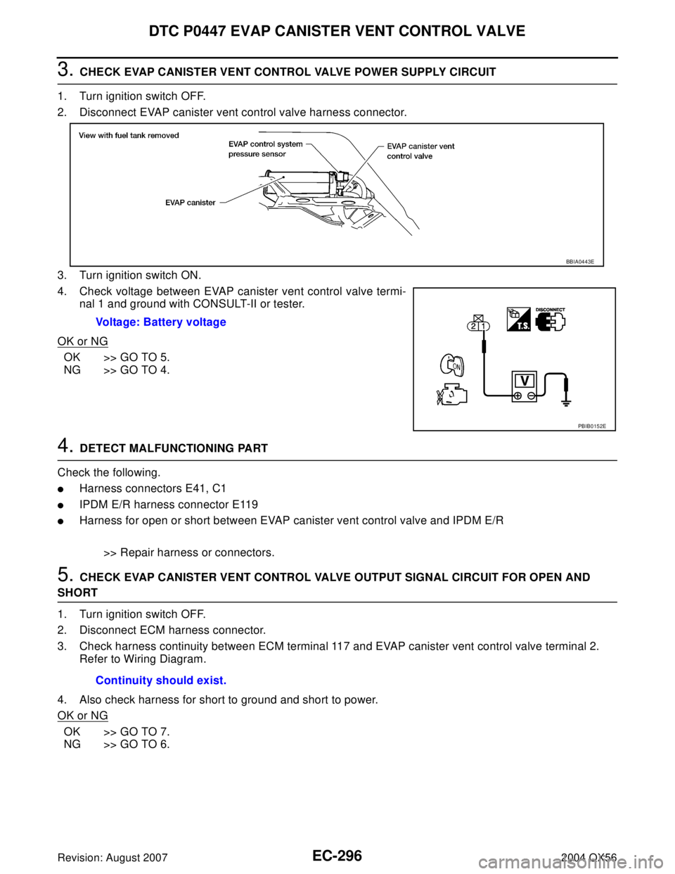
3. CHECK EVAP CANISTER VENT CONTROL VALVE POWER SUPPLY CIRCUIT
1. Turn ignition switch OFF.
2. Disconnect EVAP canister vent control valve harness connector.
3. Turn ignition switch ON.
4. Check voltage between EVAP canister vent control valve termi-
nal 1 and ground with CONSULT-II or tester.
OK or NG
OK >> GO TO 5.
NG >> GO TO 4.
4. DETECT MALFUNCTIONING PART
Check the following.
�Harness connectors E41, C1
�IPDM E/R harness connector E119
�Harness for open or short between EVAP canister vent control valve and IPDM E/R
>> Repair harness or connectors.
5. CHECK EVAP CANISTER VENT CONTROL VALVE OUTPUT SIGNAL CIRCUIT FOR OPEN AND
SHORT
1. Turn ignition switch OFF.
2. Disconnect ECM harness connector.
3. Check harness continuity between ECM terminal 117 and EVAP canister vent control valve terminal 2.
Refer to Wiring Diagram.
4. Also check harness for short to ground and short to power.
OK or NG
OK >> GO TO 7.
NG >> GO TO 6.Voltage: Battery voltage
BBIA0443E
PBIB0152E
Continuity should exist.
Page 1492 of 3371

DTC P0451 EVAP CONTROL SYSTEM PRESSURE SENSOR
EC-301
C
D
E
F
G
H
I
J
K
L
MA
EC
Revision: August 20072004 QX56
2. CHECK EVAP CONTROL SYSTEM PRESSURE SENSOR CONNECTOR FOR WATER
1. Disconnect EVAP control system pressure sensor harness connector.
2. Check sensor harness connector for water.
OK or NG
OK >> GO TO 3.
NG >> Repair or replace harness connector.
3. CHECK EVAP CONTROL SYSTEM PRESSURE SENSOR
Refer to EC-301, "
Component Inspection" .
OK or NG
OK >> GO TO 4.
NG >> Replace EVAP control system pressure sensor.
4. CHECK INTERMITTENT INCIDENT
Refer to EC-127, "
TROUBLE DIAGNOSIS FOR INTERMITTENT INCIDENT" .
For wiring diagram, refer to EC-304, "
Wiring Diagram" .
>>INSPECTION END
Component InspectionUBS00H5B
EVAP CONTROL SYSTEM PRESSURE SENSOR
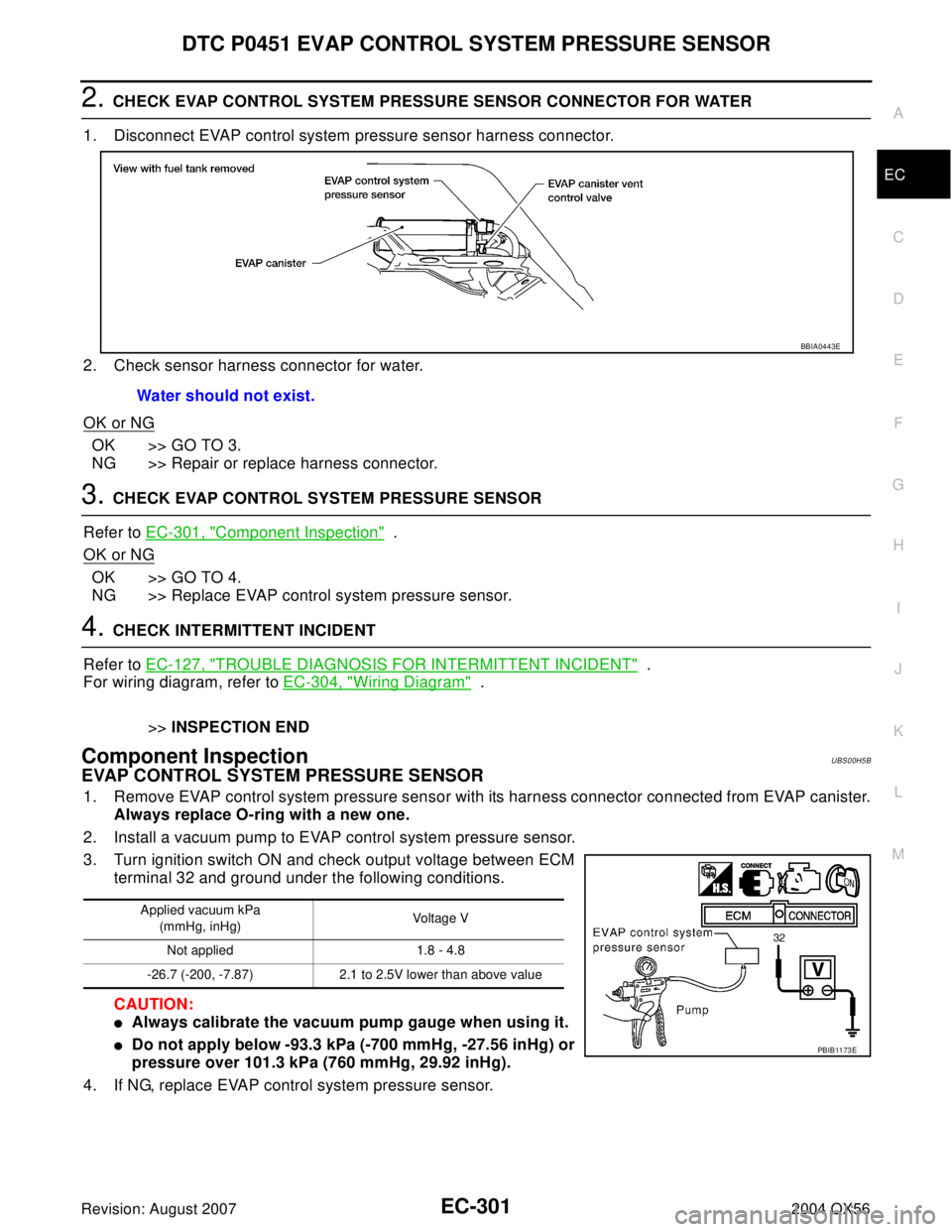
1. Remove EVAP control system pressure sensor with its harness connector connected from EVAP canister.
Always replace O-ring with a new one.
2. Install a vacuum pump to EVAP control system pressure sensor.
3. Turn ignition switch ON and check output voltage between ECM
terminal 32 and ground under the following conditions.
CAUTION:
�Always calibrate the vacuum pump gauge when using it.
�Do not apply below -93.3 kPa (-700 mmHg, -27.56 inHg) or
pressure over 101.3 kPa (760 mmHg, 29.92 inHg).
4. If NG, replace EVAP control system pressure sensor.Water should not exist.
BBIA0443E
Applied vacuum kPa
(mmHg, inHg)Voltage V
Not applied 1.8 - 4.8
-26.7 (-200, -7.87) 2.1 to 2.5V lower than above value
PBIB11 73 E
Page 1495 of 3371
EC-304Revision: August 2007
DTC P0452 EVAP CONTROL SYSTEM PRESSURE SENSOR
2004 QX56
Wiring DiagramUBS00H5G
BBWA1689E
Page 1497 of 3371

EC-306Revision: August 2007
DTC P0452 EVAP CONTROL SYSTEM PRESSURE SENSOR
2004 QX56
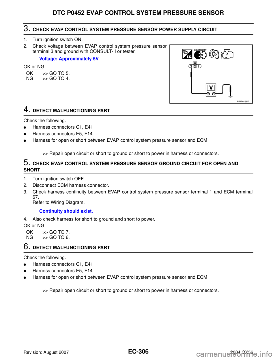
3. CHECK EVAP CONTROL SYSTEM PRESSURE SENSOR POWER SUPPLY CIRCUIT
1. Turn ignition switch ON.
2. Check voltage between EVAP control system pressure sensor
terminal 3 and ground with CONSULT-II or tester.
OK or NG
OK >> GO TO 5.
NG >> GO TO 4.
4. DETECT MALFUNCTIONING PART
Check the following.
�Harness connectors C1, E41
�Harness connectors E5, F14
�Harness for open or short between EVAP control system pressure sensor and ECM
>> Repair open circuit or short to ground or short to power in harness or connectors.
5. CHECK EVAP CONTROL SYSTEM PRESSURE SENSOR GROUND CIRCUIT FOR OPEN AND
SHORT
1. Turn ignition switch OFF.
2. Disconnect ECM harness connector.
3. Check harness continuity between EVAP control system pressure sensor terminal 1 and ECM terminal
67.
Refer to Wiring Diagram.
4. Also check harness for short to ground and short to power.
OK or NG
OK >> GO TO 7.
NG >> GO TO 6.
6. DETECT MALFUNCTIONING PART
Check the following.
�Harness connectors C1, E41
�Harness connectors E5, F14
�Harness for open or short between EVAP control system pressure sensor and ECM
>> Repair open circuit or short to ground or short to power in harness or connectors. Voltage: Approximately 5V
PBIB0138E
Continuity should exist.
Page 1498 of 3371

DTC P0452 EVAP CONTROL SYSTEM PRESSURE SENSOR
EC-307
C
D
E
F
G
H
I
J
K
L
MA
EC
Revision: August 20072004 QX56
7. CHECK EVAP CONTROL SYSTEM PRESSURE SENSOR INPUT SIGNAL CIRCUIT FOR OPEN AND
SHORT
1. Check harness continuity between ECM terminal 32 and EVAP control system pressure sensor terminal
2.
Refer to Wiring Diagram.
2. Also check harness for short to ground and short to power.
OK or NG
OK >> GO TO 9.
NG >> GO TO 8.
8. DETECT MALFUNCTIONING PART
Check the following.
�Harness connectors C1, E41
�Harness connectors E5, F14
�Harness for open or short between EVAP control system pressure sensor and ECM
>> Repair open circuit or short to ground or short to power in harness or connectors.
9. CHECK EVAP CONTROL SYSTEM PRESSURE SENSOR
Refer to EC-307, "
Component Inspection" .
OK or NG
OK >> GO TO 10.
NG >> Replace EVAP control system pressure sensor.
10. CHECK INTERMITTENT INCIDENT
Refer to EC-127, "
TROUBLE DIAGNOSIS FOR INTERMITTENT INCIDENT" .
>>INSPECTION END
Component InspectionUBS00H5I
EVAP CONTROL SYSTEM PRESSURE SENSOR
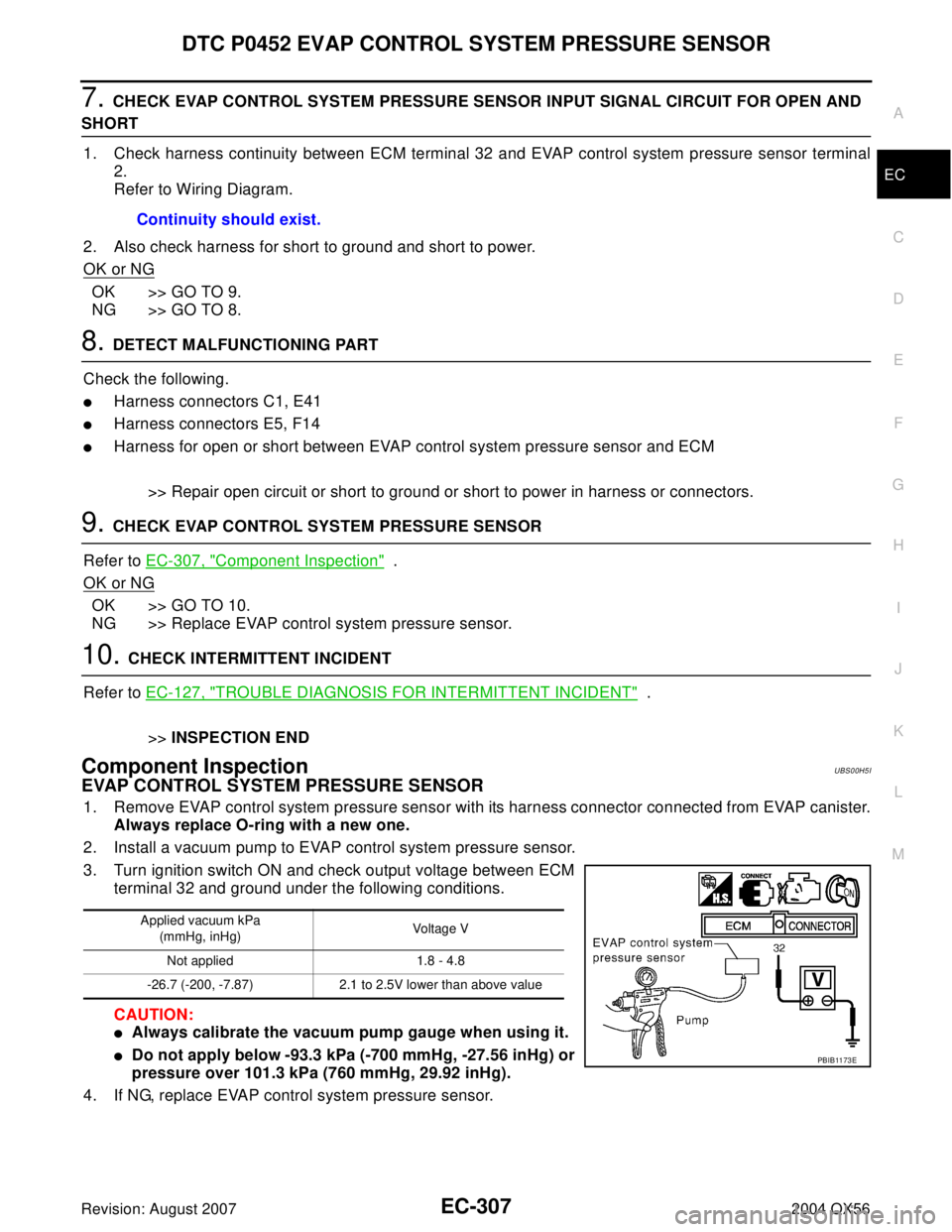
1. Remove EVAP control system pressure sensor with its harness connector connected from EVAP canister.
Always replace O-ring with a new one.
2. Install a vacuum pump to EVAP control system pressure sensor.
3. Turn ignition switch ON and check output voltage between ECM
terminal 32 and ground under the following conditions.
CAUTION:
�Always calibrate the vacuum pump gauge when using it.
�Do not apply below -93.3 kPa (-700 mmHg, -27.56 inHg) or
pressure over 101.3 kPa (760 mmHg, 29.92 inHg).
4. If NG, replace EVAP control system pressure sensor.Continuity should exist.
Applied vacuum kPa
(mmHg, inHg)Voltage V
Not applied 1.8 - 4.8
-26.7 (-200, -7.87) 2.1 to 2.5V lower than above value
PBIB11 73 E
Page 1501 of 3371
EC-310Revision: August 2007
DTC P0453 EVAP CONTROL SYSTEM PRESSURE SENSOR
2004 QX56
Wiring DiagramUBS00H5N
BBWA11 75 E
Page 1504 of 3371

DTC P0453 EVAP CONTROL SYSTEM PRESSURE SENSOR
EC-313
C
D
E
F
G
H
I
J
K
L
MA
EC
Revision: August 20072004 QX56
5. CHECK EVAP CONTROL SYSTEM PRESSURE SENSOR GROUND CIRCUIT FOR OPEN AND
SHORT
1. Turn ignition switch OFF.
2. Disconnect ECM harness connector.
3. Check harness continuity between EVAP control system pressure sensor terminal 1 and ECM terminal
67.
Refer to Wiring Diagram.
4. Also check harness for short to ground and short to power.
OK or NG
OK >> GO TO 7.
NG >> GO TO 6.
6. DETECT MALFUNCTIONING PART
Check the following.
�Harness connectors C1, E41
�Harness connectors E5, F14
�Harness for open or short between EVAP control system pressure sensor and ECM
>> Repair open circuit or short to ground or short to power in harness or connectors.
7. CHECK EVAP CONTROL SYSTEM PRESSURE SENSOR INPUT SIGNAL CIRCUIT FOR OPEN AND
SHORT
1. Check harness continuity between ECM terminal 32 and EVAP control system pressure sensor terminal
2.
Refer to Wiring Diagram.
2. Also check harness for short to ground and short to power.
OK or NG
OK >> GO TO 9.
NG >> GO TO 8.
8. DETECT MALFUNCTIONING PART
Check the following.
�Harness connectors C1, E41
�Harness connectors E5, F14
�Harness for open or short between EVAP control system pressure sensor and ECM
>> Repair open circuit or short to ground or short to power in harness or connectors.
9. CHECK RUBBER TUBE
1. Disconnect rubber tube connected to EVAP canister vent control valve.
2. Check the rubber tube for clogging, vent or kinked.
OK or NG
OK >> GO TO 10.
NG >> Clean the rubber tube using an air blower, repair or replace rubber tube.Continuity should exist.
Continuity should exist.