Page 1627 of 3371

EC-436Revision: August 2007
DTC P1271, P1281 A/F SENSOR 1
2004 QX56
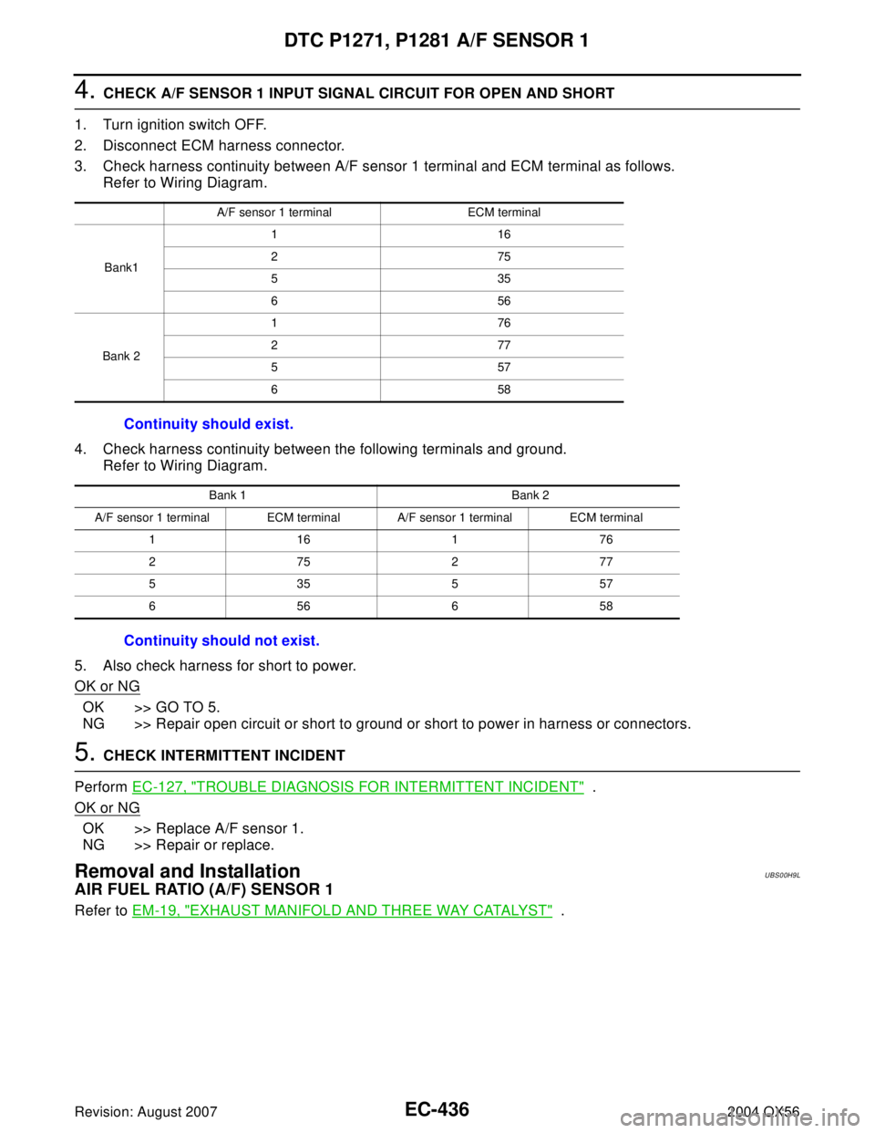
4. CHECK A/F SENSOR 1 INPUT SIGNAL CIRCUIT FOR OPEN AND SHORT
1. Turn ignition switch OFF.
2. Disconnect ECM harness connector.
3. Check harness continuity between A/F sensor 1 terminal and ECM terminal as follows.
Refer to Wiring Diagram.
4. Check harness continuity between the following terminals and ground.
Refer to Wiring Diagram.
5. Also check harness for short to power.
OK or NG
OK >> GO TO 5.
NG >> Repair open circuit or short to ground or short to power in harness or connectors.
5. CHECK INTERMITTENT INCIDENT
Perform EC-127, "
TROUBLE DIAGNOSIS FOR INTERMITTENT INCIDENT" .
OK or NG
OK >> Replace A/F sensor 1.
NG >> Repair or replace.
Removal and InstallationUBS00H9L
AIR FUEL RATIO (A/F) SENSOR 1
Refer to EM-19, "EXHAUST MANIFOLD AND THREE WAY CATALYST" .
A/F sensor 1 terminal ECM terminal
Bank1116
275
535
656
Bank 2176
277
557
658
Continuity should exist.
Bank 1 Bank 2
A/F sensor 1 terminal ECM terminal A/F sensor 1 terminal ECM terminal
116176
275277
535557
656658
Continuity should not exist.
Page 1630 of 3371
DTC P1272, P1282 A/F SENSOR 1
EC-439
C
D
E
F
G
H
I
J
K
L
MA
EC
Revision: August 20072004 QX56
Wiring DiagramUBS00H9Q
BANK 1
BBWA1369E
Page 1635 of 3371

EC-444Revision: August 2007
DTC P1272, P1282 A/F SENSOR 1
2004 QX56
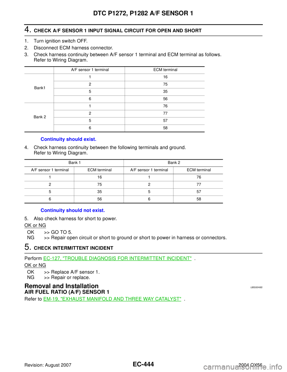
4. CHECK A/F SENSOR 1 INPUT SIGNAL CIRCUIT FOR OPEN AND SHORT
1. Turn ignition switch OFF.
2. Disconnect ECM harness connector.
3. Check harness continuity between A/F sensor 1 terminal and ECM terminal as follows.
Refer to Wiring Diagram.
4. Check harness continuity between the following terminals and ground.
Refer to Wiring Diagram.
5. Also check harness for short to power.
OK or NG
OK >> GO TO 5.
NG >> Repair open circuit or short to ground or short to power in harness or connectors.
5. CHECK INTERMITTENT INCIDENT
Perform EC-127, "
TROUBLE DIAGNOSIS FOR INTERMITTENT INCIDENT" .
OK or NG
OK >> Replace A/F sensor 1.
NG >> Repair or replace.
Removal and InstallationUBS00H9S
AIR FUEL RATIO (A/F) SENSOR 1
Refer to EM-19, "EXHAUST MANIFOLD AND THREE WAY CATALYST" .
A/F sensor 1 terminal ECM terminal
Bank1116
275
535
656
Bank 2176
277
557
658
Continuity should exist.
Bank 1 Bank 2
A/F sensor 1 terminal ECM terminal A/F sensor 1 terminal ECM terminal
116176
275277
535557
656658
Continuity should not exist.
Page 1638 of 3371
DTC P1273, P1283 A/F SENSOR 1
EC-447
C
D
E
F
G
H
I
J
K
L
MA
EC
Revision: August 20072004 QX56
Wiring Diagram UBS00H9X
BANK 1
BBWA1369E
Page 1644 of 3371

DTC P1273, P1283 A/F SENSOR 1
EC-453
C
D
E
F
G
H
I
J
K
L
MA
EC
Revision: August 20072004 QX56
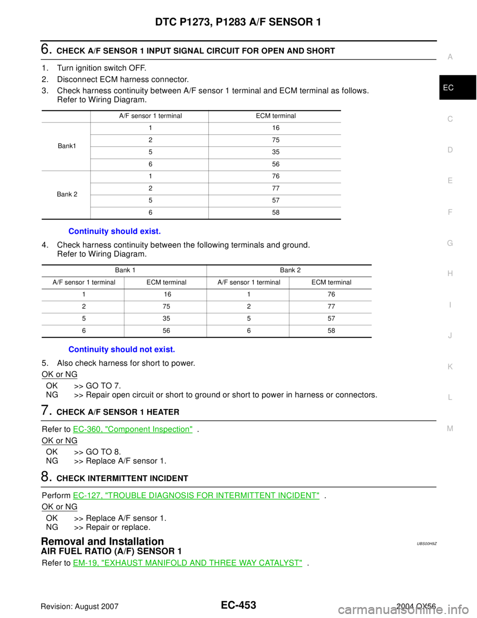
6. CHECK A/F SENSOR 1 INPUT SIGNAL CIRCUIT FOR OPEN AND SHORT
1. Turn ignition switch OFF.
2. Disconnect ECM harness connector.
3. Check harness continuity between A/F sensor 1 terminal and ECM terminal as follows.
Refer to Wiring Diagram.
4. Check harness continuity between the following terminals and ground.
Refer to Wiring Diagram.
5. Also check harness for short to power.
OK or NG
OK >> GO TO 7.
NG >> Repair open circuit or short to ground or short to power in harness or connectors.
7. CHECK A/F SENSOR 1 HEATER
Refer to EC-360, "
Component Inspection" .
OK or NG
OK >> GO TO 8.
NG >> Replace A/F sensor 1.
8. CHECK INTERMITTENT INCIDENT
Perform EC-127, "
TROUBLE DIAGNOSIS FOR INTERMITTENT INCIDENT" .
OK or NG
OK >> Replace A/F sensor 1.
NG >> Repair or replace.
Removal and InstallationUBS00H9Z
AIR FUEL RATIO (A/F) SENSOR 1
Refer to EM-19, "EXHAUST MANIFOLD AND THREE WAY CATALYST" .
A/F sensor 1 terminal ECM terminal
Bank1116
275
535
656
Bank 2176
277
557
658
Continuity should exist.
Bank 1 Bank 2
A/F sensor 1 terminal ECM terminal A/F sensor 1 terminal ECM terminal
1 161 76
275277
535557
656658
Continuity should not exist.
Page 1647 of 3371
EC-456Revision: August 2007
DTC P1274, P1284 A/F SENSOR 1
2004 QX56
Wiring Diagram UBS00HA4
BANK 1
BBWA1369E
Page 1653 of 3371

EC-462Revision: August 2007
DTC P1274, P1284 A/F SENSOR 1
2004 QX56
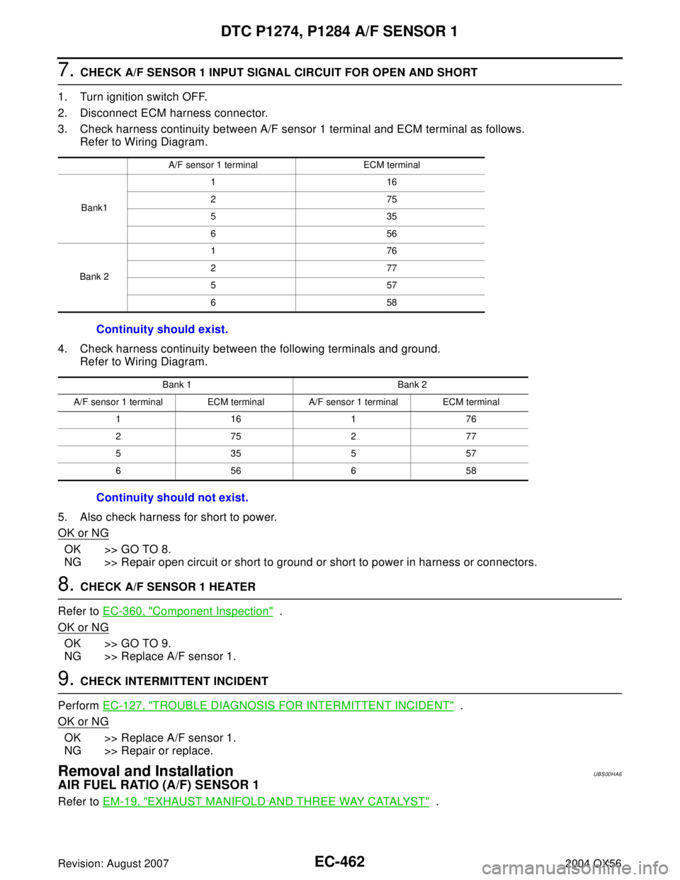
7. CHECK A/F SENSOR 1 INPUT SIGNAL CIRCUIT FOR OPEN AND SHORT
1. Turn ignition switch OFF.
2. Disconnect ECM harness connector.
3. Check harness continuity between A/F sensor 1 terminal and ECM terminal as follows.
Refer to Wiring Diagram.
4. Check harness continuity between the following terminals and ground.
Refer to Wiring Diagram.
5. Also check harness for short to power.
OK or NG
OK >> GO TO 8.
NG >> Repair open circuit or short to ground or short to power in harness or connectors.
8. CHECK A/F SENSOR 1 HEATER
Refer to EC-360, "
Component Inspection" .
OK or NG
OK >> GO TO 9.
NG >> Replace A/F sensor 1.
9. CHECK INTERMITTENT INCIDENT
Perform EC-127, "
TROUBLE DIAGNOSIS FOR INTERMITTENT INCIDENT" .
OK or NG
OK >> Replace A/F sensor 1.
NG >> Repair or replace.
Removal and InstallationUBS00HA6
AIR FUEL RATIO (A/F) SENSOR 1
Refer to EM-19, "EXHAUST MANIFOLD AND THREE WAY CATALYST" .
A/F sensor 1 terminal ECM terminal
Bank1116
275
535
656
Bank 2176
277
557
658
Continuity should exist.
Bank 1 Bank 2
A/F sensor 1 terminal ECM terminal A/F sensor 1 terminal ECM terminal
116176
275277
535557
656658
Continuity should not exist.
Page 1657 of 3371
EC-466Revision: August 2007
DTC P1276, P1286 A/F SENSOR 1
2004 QX56
Wiring DiagramUBS00HAC
BANK 1
BBWA1369E