Page 21 of 3371
![INFINITI QX56 2004 Factory Service Manual ACS-12
[ICC]
LASER BEAM AIMING ADJUSTMENT
Revision: August 20072004 QX56
LASER BEAM AIMING ADJUSTMENTPFP:00026
Outline of Laser Beam Aiming Adjustment ProcedureEKS007TI
CAUTION:
�The laser beam aiming](/manual-img/42/57034/w960_57034-20.png "INFINITI QX56 2004 Factory Service Manual ACS-12
[ICC]
LASER BEAM AIMING ADJUSTMENT
Revision: August 20072004 QX56
LASER BEAM AIMING ADJUSTMENTPFP:00026
Outline of Laser Beam Aiming Adjustment ProcedureEKS007TI
CAUTION:
�The laser beam aiming")
ACS-12
[ICC]
LASER BEAM AIMING ADJUSTMENT
Revision: August 20072004 QX56
LASER BEAM AIMING ADJUSTMENTPFP:00026
Outline of Laser Beam Aiming Adjustment ProcedureEKS007TI
CAUTION:
�The laser beam aiming adjustment cannot be performed without CONSULT-II.
�The laser beam aiming adjustment must be performed every time the ICC sensor is removed,
installed or has been moved as a result of a collision.
1. Prepare the vehicle and the work area.
2. Set up the ICC target board.
3. Adjust the sensor following the procedure on CONSULT-II.
4. Check system operation after the adjustment.
PreparationEKS007PC
�Place the vehicle on level ground. Shift the transmission into "P" position and release the parking brake.
�Adjust the tire pressure to the specified value.
�See that there is no load in the vehicle. Coolant, engine oil and fuel should be filled to correct level.
�Check that the vehicle suspension has been adjusted to the standard height by the load leveling rear air
suspension system. Refer to RSU-12, "
Basic Inspection" .
�Clean the ICC sensor with a soft cloth.
Setting up the ICC Target BoardEKS007PE
CAUTION:
Accuracy in setting up the ICC target board is essential for the laser beam aiming adjustment.
ADJUSTING HEIGHT OF THE ICC TARGET BOARD
1. Attach a triangle scale as shown.Tool number : KV99110100 (J-45718)
WKIA1848E
WKIA1849E
Page 81 of 3371
AT-10
PREPARATION
Revision: August 20072004 QX56
PREPARATIONPFP:00002
Special Service ToolsUCS002C6
The actual shapes of Kent-Moore tools may differ from those of special service tools illustrated here.
Tool number
(Kent-Moore No.)
Tool nameDescription
ST2505S001
(J-34301-C)
Oil pressure gauge set
1 ST25051001
(—)
Oil pressure gauge
2 ST25052000
(—)
Hose
3 ST25053000
(—)
Joint pipe
4 ST25054000
(—)
Adapter
5 ST25055000
(—)
AdapterMeasuring line pressure
KV31103600
(J-45674)
Joint pipe adapter
(With ST25054000)Measuring line pressure
ST33400001
(J-26082)
Drift
a: 60 mm (2.36 in) dia.
b: 47 mm (1.85 in) dia.
�Installing rear oil seal (2WD models)
�Installing oil pump housing oil seal
KV31102400
(J-34285 and J-34285-87)
Clutch spring compressor
a: 320 mm (12.60 in)
b: 174 mm (6.85 in)Installing reverse brake return spring retainer
ZZA0600D
ZZA1227D
NT086
NT423
Page 82 of 3371
PREPARATION
AT-11
D
E
F
G
H
I
J
K
L
MA
B
AT
Revision: August 20072004 QX56
ST25850000
(J-25721-A)
Sliding hammer
a: 179 mm (7.05 in)
b: 70 mm (2.76 in)
c: 40 mm (1.57 in)
d: M12X1.75PRemove oil pump assembly
—
(J-47002)
Transmission jack adapter kit
—
(J-47002-1)
Center bracket (Pathfinder with All-
Mode 4WD)
—
(J-47002-2)
Center bracket (Titan and Armada)
—
(J-47002-3)
Adapter plate
—
(J-47002-4)
Adapter blockAssist in removal of transmission and transfer
case as one assembly using only one trans-
mission jack. Tool number
(Kent-Moore No.)
Tool nameDescription
NT422
LCIA0364E
Page 419 of 3371

ATC-14
PREPARATION
Revision: August 20072004 QX56
PREPARATIONPFP:00002
Special Service ToolsEJS002BP
The actual shapes of Kent-Moore tools may differ from those of special service tools illustrated here.
HFC-134a (R-134a) Service Tools and EquipmentEJS002BQ
Never mix HFC-134a refrigerant and/or its specified lubricant with CFC-12 (R-12) refrigerant and/or its lubri-
cant.
Separate and non-interchangeable service equipment must be used for handling each type of refrigerant/lubri-
cant.
Refrigerant container fittings, service hose fittings and service equipment fittings (equipment which handles
refrigerant and/or lubricant) are different between CFC-12 (R-12) and HFC-134a (R-134a). This is to avoid
mixed use of the refrigerants/lubricant.
Adapters that convert one size fitting to another must never be used refrigerant/lubricant contamination will
occur and compressor failure will result.
Tool number
(Kent-Moore No.)
Tool nameDescription
—
(J-38873-A)
Drive plate installerInstalling pulley and drive plate
KV99233130
(J-29884)
Pulley pullerRemoving pulley
WJIA0367E
LHA172
Tool number
(Kent-Moore No.)
Tool nameDescription
HFC-134a (R-134a) refrigerant Container color: Light blue
Container marking: HFC-134a (R-
134a)
Fitting size: Thread size
�large container 1/2"-16 ACME
KLH00-PAGS0
(—)
Nissan A/C System Oil Type DH-
PSType: Poly alkylene glycol oil (PAG),
type DH-PS
Application: HFC-134a (R-134a)
swash plate compressors (Nissan
only)
Lubricity: 40 m (1.4 US fl oz, 1.4 Imp
fl oz)
KV991J0130
(ACR2005-NI)
ACR A/C Service CenterRefrigerant recovery, recycling and re-
charging
S-NT196
S-NT197
WJIA0293E
Page 420 of 3371

Electronic refrigerant leak detectorPower supply:
�DC 12V (battery terminal)
(J-43926)
Refrigerant dye leak dete")
PREPARATION
ATC-15
C
D
E
F
G
H
I
K
L
MA
B
AT C
Revision: August 20072004 QX56
(J-41995)
Electronic refrigerant leak detectorPower supply:
�DC 12V (battery terminal)
(J-43926)
Refrigerant dye leak detection kit
Kit includes:
(J-42220)
UV lamp and UV safety goggles
(J-41459)
Refrigerant dye injector
(J-41447)
HFC-134a (R-134a) Fluorescent
leak detection dye
(Box of 24, 1/4 ounce bottles)
(J-43872)
Refrigerant dye cleanerPower supply:
�DC 12V (battery terminal)
(J-42220)
UV lamp and UV safety gogglesPower supply:
�DC 12V (battery terminal)
For checking refrigerant leak when flu-
orescent dye is installed in A/C system.
Includes: UV lamp and UV safety gog-
gles
(J-41447)
HFC-134a (R-134a) Fluorescent
leak detection dye
(Box of 24, 1/4 ounce bottles)Application: For HFC-134a (R-134a)
PAG oil
Container: 1/4 ounce (7.4cc) bottle
(Includes self-adhesive dye identifica-
tion labels for affixing to vehicle after
charging system with dye.)
(J-41459)
HFC-134a (R-134a) Dye injector
Use with J-41447, 1/4 ounce bottleFor injecting 1/4 ounce of fluorescent
leak detection dye into A/C system.
(J-43872)
Refrigerant dye cleanerFor cleaning dye spills. Tool number
(Kent-Moore No.)
Tool nameDescription
AHA2 81 A
ZHA2 00 H
SHA438F
SHA439F
SHA440F
SHA441F
Page 421 of 3371

Manifold gauge set (with hoses
and couplers)Identification:
�The gauge face indicates R-134a.
Fitting size-Thread size
�1/2\"-16 ACME
Serv")
ATC-16
PREPARATION
Revision: August 20072004 QX56
(J-39183-C)
Manifold gauge set (with hoses
and couplers)Identification:
�The gauge face indicates R-134a.
Fitting size-Thread size
�1/2"-16 ACME
Service hoses
�High side hose
(J-39500-72B)
�Low side hose
(J-39500-72R)
�Utility hose
(J-39500-72Y)
Hose color:
�Low side hose: Blue with black stripe
�High side hose: Red with black stripe
�Utility hose: Yellow with black stripe
or green with black stripe
Hose fitting to gauge:
�1/2"-16 ACME
Service couplers
�High side coupler
(J-39500-20A)
�Low side coupler
(J-39500-24A)
Hose fitting to service hose:
�M14 x 1.5 fitting is optional or perma-
nently attached.
(J-39699)
Refrigerant weight scaleFor measuring of refrigerant
Fitting size-Thread size
�1/2"-16 ACME
(J-39649)
Vacuum pump
(Including the isolator valve)
Capacity:
�Air displacement: 4 CFM
�Micron rating: 20 microns
�Oil capacity: 482 g (17 oz)
Fitting size-Thread size
�1/2"-16 ACME Tool number
(Kent-Moore No.)
Tool nameDescription
RJIA0196E
S-NT201
S-NT202
S-NT200
S-NT203
Page 572 of 3371
REFRIGERANT LINES
ATC-167
C
D
E
F
G
H
I
K
L
MA
B
AT C
Revision: August 20072004 QX56
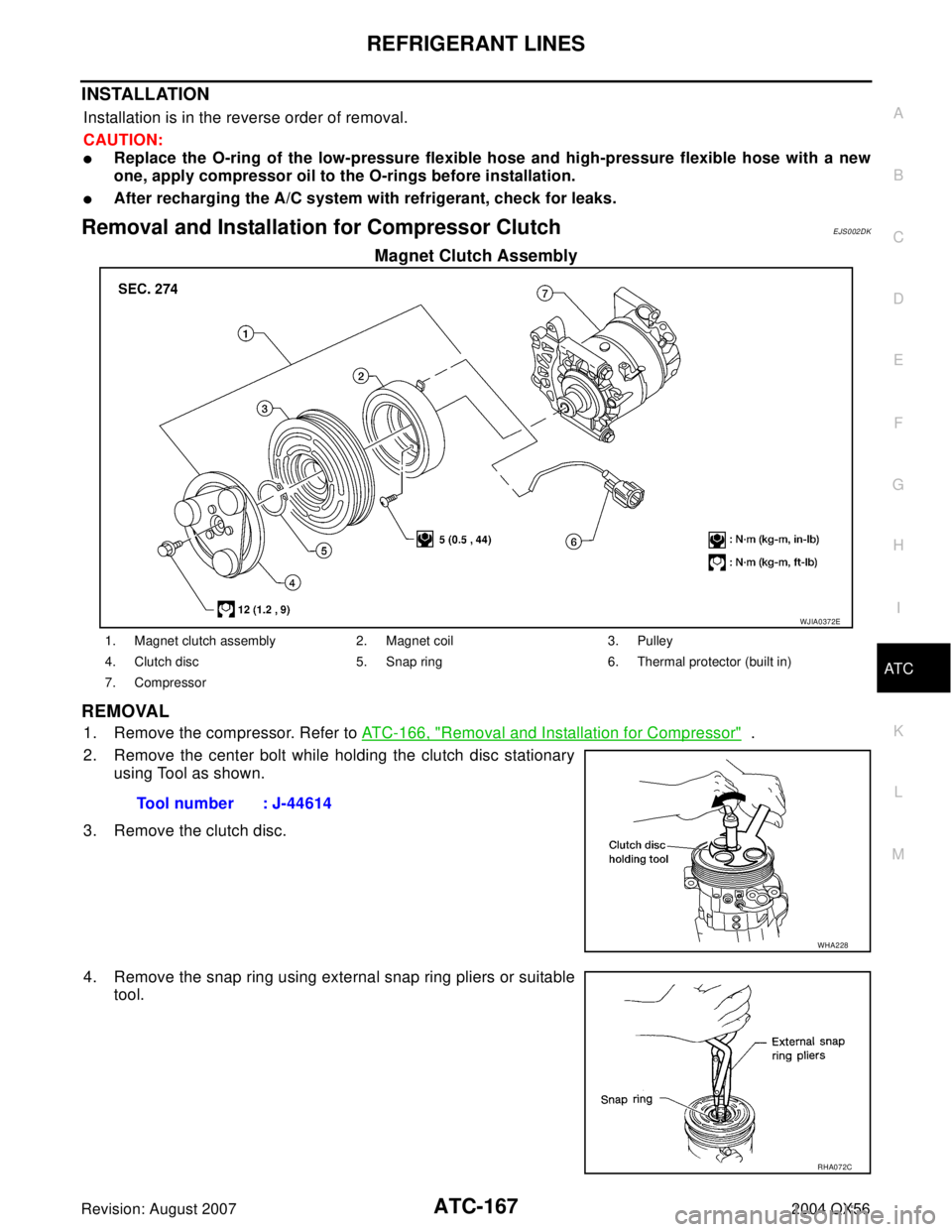
INSTALLATION
Installation is in the reverse order of removal.
CAUTION:
�Replace the O-ring of the low-pressure flexible hose and high-pressure flexible hose with a new
one, apply compressor oil to the O-rings before installation.
�After recharging the A/C system with refrigerant, check for leaks.
Removal and Installation for Compressor ClutchEJS002DK
Magnet Clutch Assembly
REMOVAL
1. Remove the compressor. Refer to ATC-166, "Removal and Installation for Compressor" .
2. Remove the center bolt while holding the clutch disc stationary
using Tool as shown.
3. Remove the clutch disc.
4. Remove the snap ring using external snap ring pliers or suitable
tool.
WJIA0372E
1. Magnet clutch assembly 2. Magnet coil 3. Pulley
4. Clutch disc 5. Snap ring 6. Thermal protector (built in)
7. Compressor
Tool number : J-44614
WHA228
RHA072C
Page 574 of 3371

REFRIGERANT LINES
ATC-169
C
D
E
F
G
H
I
K
L
MA
B
AT C
Revision: August 20072004 QX56
2. Install the magnet coil harness clip using a screwdriver.
3. Install the pulley assembly using Tool and a wrench, then install
the snap ring using snap ring pliers.
4. Install the clutch disc on the compressor shaft, together with the
original shim(s). Press the clutch disc down by hand.
5. Install the clutch pulley bolt using Tool, to prevent the clutch disc
from turning and tighten the bolt to specification. Refer to AT C -
164, "Components" .
CAUTION:
After tightening the clutch pulley bolt, check that the clutch
pulley rotates smoothly.
6. Check the pulley clearance all the way around the clutch disc as
shown.
7. If the specified clearance is not obtained, replace the adjusting
spacer to readjust.
8. Connect the compressor electrical connector.
9. Install the drive belt. Refer to EM-13, "
Installation" .
10. Install the engine under cover and the splash shield.Tool number : — (J-38873-A)
WJIA0368E
WHA184
Tool number : J-44614
WHA229
Clutch disc-to-pulley clearance : 0.3 - 0.6 mm
(0.012 - 0.024 in)
WHA194


Sliding hammer
a: 179 mm (7.05 in)
b: 70 mm (2.76 in)
c: 40 mm (1.57 in)
d: M12X1.75PRemove oil pump a")