Page 1589 of 3371
EC-398Revision: August 2007
DTC P1147, P1167 HO2S2
2004 QX56
Wiring DiagramUBS00H8G
BANK 1
BBWA11 58 E
Page 1594 of 3371
DTC P1147, P1167 HO2S2
EC-403
C
D
E
F
G
H
I
J
K
L
MA
EC
Revision: August 20072004 QX56
3. CHECK HO2S2 GROUND CIRCUIT FOR OPEN AND SHORT
1. Turn ignition switch OFF.
2. Disconnect heated oxygen sensor 2 harness connector.
3. Check harness continuity between HO2S2 terminal 4 and body ground.
Refer to Wiring Diagram.
4. Also check harness for short to power.
OK or NG
OK >> GO TO 5.
NG >> GO TO 4.
4. DETECT MALFUNCTIONING PART
Check the following.
�Harness connectors F14, E5
�Harness for open or short between HO2S2 and body ground
>> Repair open circuit or short to power in harness or connectors. Continuity should exist.
BBIA0435E
Page 1595 of 3371

EC-404Revision: August 2007
DTC P1147, P1167 HO2S2
2004 QX56
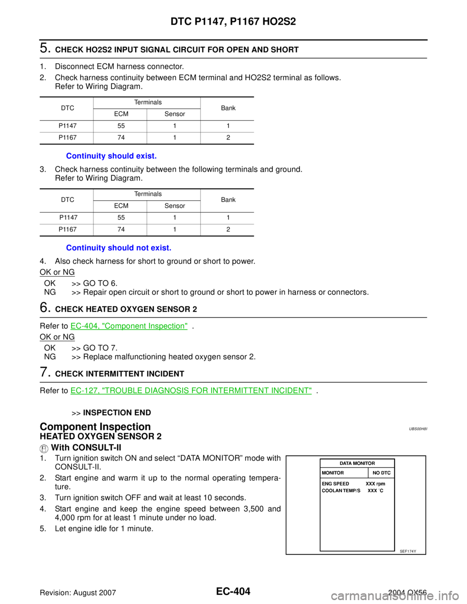
5. CHECK HO2S2 INPUT SIGNAL CIRCUIT FOR OPEN AND SHORT
1. Disconnect ECM harness connector.
2. Check harness continuity between ECM terminal and HO2S2 terminal as follows.
Refer to Wiring Diagram.
3. Check harness continuity between the following terminals and ground.
Refer to Wiring Diagram.
4. Also check harness for short to ground or short to power.
OK or NG
OK >> GO TO 6.
NG >> Repair open circuit or short to ground or short to power in harness or connectors.
6. CHECK HEATED OXYGEN SENSOR 2
Refer to EC-404, "
Component Inspection" .
OK or NG
OK >> GO TO 7.
NG >> Replace malfunctioning heated oxygen sensor 2.
7. CHECK INTERMITTENT INCIDENT
Refer to EC-127, "
TROUBLE DIAGNOSIS FOR INTERMITTENT INCIDENT" .
>>INSPECTION END
Component InspectionUBS00H8I
HEATED OXYGEN SENSOR 2
With CONSULT-II
1. Turn ignition switch ON and select “DATA MONITOR” mode with
CONSULT-II.
2. Start engine and warm it up to the normal operating tempera-
ture.
3. Turn ignition switch OFF and wait at least 10 seconds.
4. Start engine and keep the engine speed between 3,500 and
4,000 rpm for at least 1 minute under no load.
5. Let engine idle for 1 minute.
DTCTe r m i n a l s
Bank
ECM Sensor
P1147 55 1 1
P1167 74 1 2
Continuity should exist.
DTCTe r m i n a l s
Bank
ECM Sensor
P1147 55 1 1
P1167 74 1 2
Continuity should not exist.
SEF 1 74 Y
Page 1604 of 3371
DTC P1217 ENGINE OVER TEMPERATURE
EC-413
C
D
E
F
G
H
I
J
K
L
MA
EC
Revision: August 20072004 QX56
Wiring DiagramUBS00H8X
BBWA11 81 E
Page 1608 of 3371

DTC P1217 ENGINE OVER TEMPERATURE
EC-417
C
D
E
F
G
H
I
J
K
L
MA
EC
Revision: August 20072004 QX56
8. CHECK MAIN 12 CAUSES
If the cause cannot be isolated, go to EC-418, "
Main 12 Causes of Overheating" .
>>INSPECTION END
PROCEDURE A
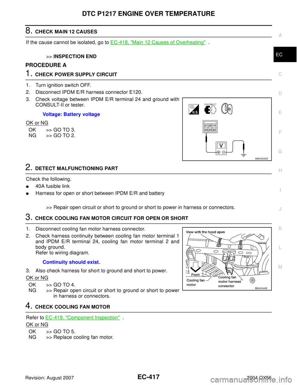
1. CHECK POWER SUPPLY CIRCUIT
1. Turn ignition switch OFF.
2. Disconnect IPDM E/R harness connector E120.
3. Check voltage between IPDM E/R terminal 24 and ground with
CONSULT-II or tester.
OK or NG
OK >> GO TO 3.
NG >> GO TO 2.
2. DETECT MALFUNCTIONING PART
Check the following.
�40A fusible link
�Harness for open or short between IPDM E/R and battery
>> Repair open circuit or short to ground or short to power in harness or connectors.
3. CHECK COOLING FAN MOTOR CIRCUIT FOR OPEN OR SHORT
1. Disconnect cooling fan motor harness connector.
2. Check harness continuity between cooling fan motor terminal 1
and IPDM E/R terminal 24, cooling fan motor terminal 2 and
body ground.
Refer to wiring diagram.
3. Also check harness for short to ground and short to power.
OK or NG
OK >> GO TO 4.
NG >> Repair open circuit or short to ground or short to power
in harness or connectors.
4. CHECK COOLING FAN MOTOR
Refer to EC-419, "
Component Inspection" .
OK or NG
OK >> GO TO 5.
NG >> Replace cooling fan motor.Voltage: Battery voltage
WBIA0532E
Continuity should exist.
BBIA0446E
Page 1616 of 3371
DTC P1229 SENSOR POWER SUPPLY
EC-425
C
D
E
F
G
H
I
J
K
L
MA
EC
Revision: August 20072004 QX56
Wiring DiagramUBS00H9D
BBWA1699E
Page 1618 of 3371

DTC P1229 SENSOR POWER SUPPLY
EC-427
C
D
E
F
G
H
I
J
K
L
MA
EC
Revision: August 20072004 QX56
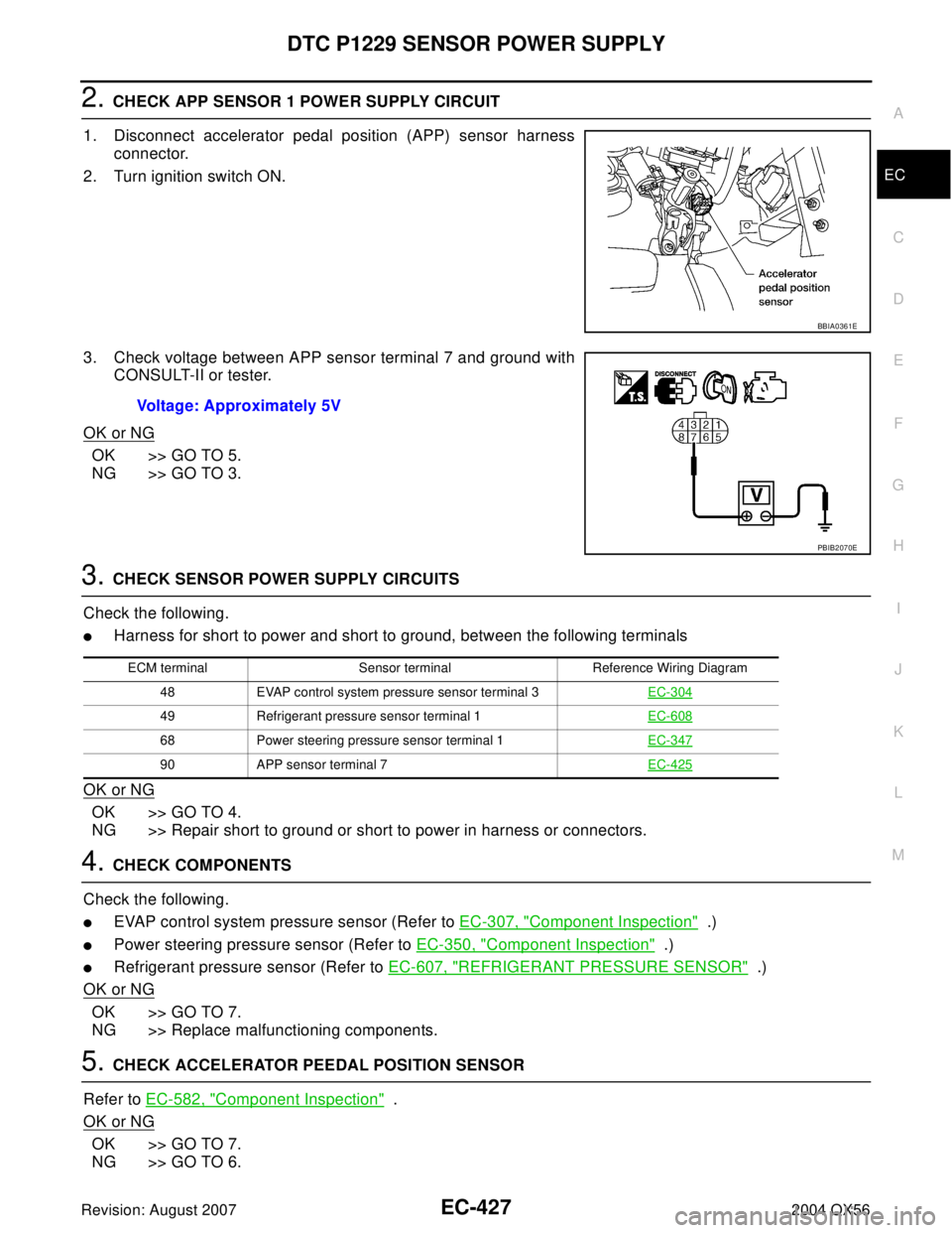
2. CHECK APP SENSOR 1 POWER SUPPLY CIRCUIT
1. Disconnect accelerator pedal position (APP) sensor harness
connector.
2. Turn ignition switch ON.
3. Check voltage between APP sensor terminal 7 and ground with
CONSULT-II or tester.
OK or NG
OK >> GO TO 5.
NG >> GO TO 3.
3. CHECK SENSOR POWER SUPPLY CIRCUITS
Check the following.
�Harness for short to power and short to ground, between the following terminals
OK or NG
OK >> GO TO 4.
NG >> Repair short to ground or short to power in harness or connectors.
4. CHECK COMPONENTS
Check the following.
�EVAP control system pressure sensor (Refer to EC-307, "Component Inspection" .)
�Power steering pressure sensor (Refer to EC-350, "Component Inspection" .)
�Refrigerant pressure sensor (Refer to EC-607, "REFRIGERANT PRESSURE SENSOR" .)
OK or NG
OK >> GO TO 7.
NG >> Replace malfunctioning components.
5. CHECK ACCELERATOR PEEDAL POSITION SENSOR
Refer to EC-582, "
Component Inspection" .
OK or NG
OK >> GO TO 7.
NG >> GO TO 6.
BBIA0361E
Voltage: Approximately 5V
PBIB2070E
ECM terminal Sensor terminal Reference Wiring Diagram
48 EVAP control system pressure sensor terminal 3EC-304
49 Refrigerant pressure sensor terminal 1EC-608
68 Power steering pressure sensor terminal 1EC-347
90 APP sensor terminal 7EC-425
Page 1622 of 3371
DTC P1271, P1281 A/F SENSOR 1
EC-431
C
D
E
F
G
H
I
J
K
L
MA
EC
Revision: August 20072004 QX56
Wiring DiagramUBS00H9J
BANK 1
BBWA1369E