Page 558 of 3371
AIR MIX DOOR MOTOR
ATC-153
C
D
E
F
G
H
I
K
L
MA
B
AT C
Revision: August 20072004 QX56
AIR MIX DOOR MOTOR PFP:27732
ComponentsEJS002DB
Air Mix Door Motors - Front Heater and Cooling Unit Assembly
Removal and InstallationEJS002DC
FRONT AIR MIX DOOR MOTOR (DRIVER)
Removal
1. Remove the front heater and cooling unit assembly. Refer to ATC-145, "FRONT HEATER AND COOLING
UNIT ASSEMBLY" .
2. Remove the steering member from the front heater and cooling unit assembly.
3. Disconnect the air mix door motor electrical connector.
4. Remove the three screws and remove the air mix door motor.
Installation
Installation is in the reverse order of removal.
LJIA0139E
1. Front heater and cooling unit assembly 2. Intake door motor 3. Air mix door motor (driver)
4. Variable blower control 5. Air mix door motor (passenger) 6. Mode door motor
7. Defroster door motor
Page 559 of 3371
ATC-154
AIR MIX DOOR MOTOR
Revision: August 20072004 QX56
FRONT AIR MIX DOOR MOTOR (PASSENGER)
Removal
1. Remove the front heater and cooling unit assembly. Refer to ATC-145, "FRONT HEATER AND COOLING
UNIT ASSEMBLY" .
2. Remove the steering member from the front heater and cooling unit assembly.
3. Disconnect the air mix door motor electrical connector.
4. Remove the three screws and remove the air mix door motor.
Installation
Installation is in the reverse order of removal.
REAR AIR MIX DOOR MOTOR
Removal
1. Remove the RH rear interior trim panel. Refer to EI-34, "Removal and Installation" .
2. Disconnect the rear air mix door motor electrical connector.
3. Remove the three screws and remove the rear air mix door
motor.
Installation
Installation is in the reverse order of removal.
LJIA0021E
Page 560 of 3371
VARIABLE BLOWER CONTROL
ATC-155
C
D
E
F
G
H
I
K
L
MA
B
AT C
Revision: August 20072004 QX56
VARIABLE BLOWER CONTROLPFP:27200
Removal and InstallationEJS002DD
Variable Blower Control - Front Heater and Cooling Unit Assembly
REMOVAL
1. Remove the front heater and cooling unit assembly. Refer to ATC-145, "FRONT HEATER AND COOLING
UNIT ASSEMBLY" .
2. Remove the steering member from the front heater and cooling unit assembly.
3. Disconnect the variable blower control electrical connector.
4. Remove the two screws and remove the variable blower control.
INSTALLATION
Installation is in the reverse order of removal.
LJIA0139E
1. Front heater and cooling unit assembly 2. Intake door motor 3. Air mix door motor (driver)
4. Variable blower control 5. Air mix door motor (passenger) 6. Mode door motor
7. Defroster door motor
Page 561 of 3371
ATC-156
REAR BLOWER MOTOR RESISTOR
Revision: August 20072004 QX56
REAR BLOWER MOTOR RESISTORPFP:27150
Removal and InstallationEJS002DE
Rear Blower Motor Resistor
REMOVAL
1. Remove the rear RH interior trim panel. Refer to EI-34, "Removal and Installation" .
2. Disconnect the rear blower motor resistor electrical connector.
3. Remove the two screws and remove the rear blower motor resistor.
INSTALLATION
Installation is in the reverse order of removal.
LJIA0055E
1. Rear blower motor 2. Rear blower motor case 3. Rear blower motor resistor
Page 565 of 3371

ATC-160
DUCTS AND GRILLES
Revision: August 20072004 QX56
Removal and InstallationEJS002DG
CENTER CONSOLE HEAT DUCT AND REAR FINISHER ASSEMBLY GRILLE
Removal
The center console must be removed and disassembled to remove the heat duct and rear finisher assembly
grille. Refer to IP-15, "
Center Console" .
Installation
Installation is in the reverse order of removal.
DEFROSTER NOZZLE
Removal
1. Remove the instrument panel trim. Refer to IP-10, "INSTRUMENT PANEL ASSEMBLY" .
2. Remove the defroster nozzle.
Installation
Installation is in the reverse order of removal.
RH AND LH SIDE DEMISTER DUCT
Removal
1. Remove the instrument panel trim. Refer to IP-10, "INSTRUMENT PANEL ASSEMBLY" .
2. Remove the RH or LH side demister duct.
Installation
Installation is in the reverse order of removal.
RH AND LH VENTILATOR DUCT
Removal
1. Remove the instrument panel trim. Refer to IP-10, "INSTRUMENT PANEL ASSEMBLY" .
2. Remove the RH or LH ventilator duct.
Installation
Installation is in the reverse order of removal.
CENTER VENTILATOR DUCT
Removal
1. Remove the instrument panel trim. Refer to IP-10, "INSTRUMENT PANEL ASSEMBLY" .
2. Remove the defroster nozzle.
3. Remove the RH and LH side demister ducts.
4. Remove the RH and LH ventilator ducts.
5. Remove the center ventilator duct.
Installation
Installation is in the reverse order of removal.
FLOOR DUCT
Removal
1. Remove the floor carpet. Refer to EI-36, "Removal and Installation" .
2. Remove the two clips and remove the floor duct.
Installation
Installation is in the reverse order of removal.
REAR OVERHEAD DUCTS
Removal
1. Remove the rear RH interior trim panel. Refer to EI-34, "Removal and Installation" .
2. Remove the headliner. Refer to EI-37, "
Removal and Installation" .
7. LH ventilator grille 8. RH ventilator grille 9. RH side ventilator and demister grille
10. Storage tray bottom cover (RH)
Page 566 of 3371

DUCTS AND GRILLES
ATC-161
C
D
E
F
G
H
I
K
L
MA
B
AT C
Revision: August 20072004 QX56
NOTE:
The rear headliner duct connected to the rear upper overhead duct is part of the headlining trim panel and
is replaced as an assembly. Refer to EI-37, "
Removal and Installation" .
3. Remove the two bolts and remove the rear lower and upper overhead ducts.
Installation
Installation is in the reverse order of removal.
REAR FLOOR DUCT
Removal
1. Remove the rear RH interior trim panel. Refer to EI-34, "Removal and Installation" .
2. Reposition the floor carpet out of the way.
3. Remove the two bolts and remove the rear floor duct.
Installation
Installation is in the reverse order of removal.
GRILLES
Removal
1. Remove the interior trim panel as necessary. Refer to IP-10, "INSTRUMENT PANEL ASSEMBLY" or EI-
37, "Removal and Installation" .
2. Remove the grille from the interior trim panel.
NOTE:
To remove the overhead console front and rear grilles, turn the grille counter-clockwise to release the
grille from the overhead console trim panel.
Installation
Installation is in the reverse order of removal.
Page 572 of 3371
REFRIGERANT LINES
ATC-167
C
D
E
F
G
H
I
K
L
MA
B
AT C
Revision: August 20072004 QX56
INSTALLATION
Installation is in the reverse order of removal.
CAUTION:
�Replace the O-ring of the low-pressure flexible hose and high-pressure flexible hose with a new
one, apply compressor oil to the O-rings before installation.
�After recharging the A/C system with refrigerant, check for leaks.
Removal and Installation for Compressor ClutchEJS002DK
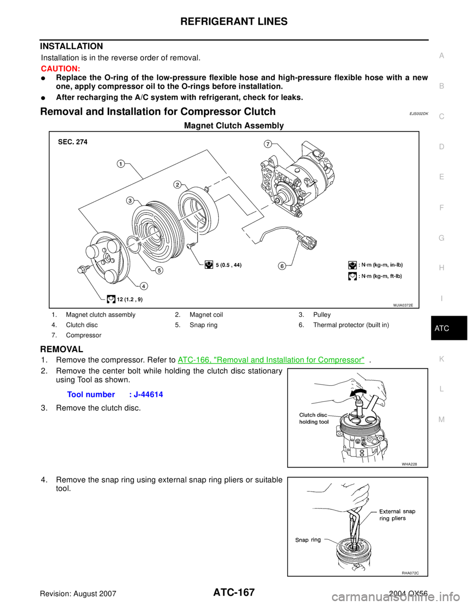
Magnet Clutch Assembly
REMOVAL
1. Remove the compressor. Refer to ATC-166, "Removal and Installation for Compressor" .
2. Remove the center bolt while holding the clutch disc stationary
using Tool as shown.
3. Remove the clutch disc.
4. Remove the snap ring using external snap ring pliers or suitable
tool.
WJIA0372E
1. Magnet clutch assembly 2. Magnet coil 3. Pulley
4. Clutch disc 5. Snap ring 6. Thermal protector (built in)
7. Compressor
Tool number : J-44614
WHA228
RHA072C
Page 575 of 3371

ATC-170
REFRIGERANT LINES
Revision: August 20072004 QX56
BREAK-IN OPERATION
When replacing compressor clutch assembly, always conduct the break-in operation. This is done by engag-
ing and disengaging the clutch about 30 times. Break-in operation raises the level of transmitted torque.
Removal and Installation for Low-pressure Flexible HoseEJS002DL
REMOVAL
1. Remove the engine room cover using power tools.
2. Remove the engine air cleaner and air ducts. Refer to EM-14, "
REMOVAL" .
3. Remove the cowl top extension. Refer to EI-18, "
COWL TOP" .
4. Discharge the refrigerant. Refer to ATC-162, "
HFC-134a (R-134a) Service Procedure" .
CAUTION:
Cap or wrap the joint of the pipe with suitable material such as vinyl tape to avoid the entry of con-
taminants.
5. Remove the low-pressure flexible hose. Refer to ATC-164, "
Components" .
INSTALLATION
Installation is in the reverse order of removal.
Refer to ATC-164, "
Components" .
CAUTION:
�Replace the O-ring of the low-pressure flexible hose with a new one, then apply compressor oil to
it when installing it.
�After charging refrigerant, check for leaks.
Removal and Installation for High-pressure Flexible HoseEJS002DM
REMOVAL
1. Remove the engine under cover.
2. Remove the engine air cleaner and air ducts. Refer to EM-14, "
REMOVAL" .
3. Discharge the refrigerant. Refer to ATC-162, "
HFC-134a (R-134a) Service Procedure" .
4. Remove the high-pressure flexible hose. Refer to ATC-164, "
Components" .
CAUTION:
Cap or wrap the joint of the hose with suitable material such as vinyl tape to avoid the entry of
contaminants.
INSTALLATION
Installation is in the reverse order of removal.
Refer to ATC-164, "
Components" .
CAUTION:
�Replace the O-ring of the high-pressure flexible hose with a new one, then apply compressor oil to
it when installing it.
�After charging refrigerant, check for leaks.
Removal and Installation for High-pressure PipeEJ S00 2DN
REMOVAL
1. Remove the cowl top extension. Refer to EI-18, "COWL TOP" .
2. Disconnect the battery negative cable.
3. Reposition the IPDM E/R aside.
4. Remove the front right wheel and tire assembly. Refer to WT-6, "
Rotation" .
5. Position aside the front floor insulator.
6. Discharge the refrigerant. Refer to ATC-162, "
HFC-134a (R-134a) Service Procedure" .
7. Remove the low pressure pipe. Refer to ATC-171, "
Removal and Installation for Low-pressure Pipe" .
8. Remove the high-pressure pipe. Refer to ATC-164, "
Components" .
CAUTION:
Cap or wrap the joint of the pipe with suitable material such as vinyl tape to avoid the entry of con-
taminants.


Removal
1. Remove the front heater and cooling unit assembly. Refer to ATC-145, \"FRONT HEATER AND COOLING")