Page 2374 of 4449
![INFINITI FX35 2004 Service Manual DTC P0456 EVAP CONTROL SYSTEM
EC-1033
[VK45DE]
C
D
E
F
G
H
I
J
K
L
MA
EC
Revision: 2004 November 2004 FX35/FX45
2. Set the pressure pump and a hose.
3. Also set a vacuum gauge via 3-way connector and](/manual-img/42/57021/w960_57021-2373.png "INFINITI FX35 2004 Service Manual DTC P0456 EVAP CONTROL SYSTEM
EC-1033
[VK45DE]
C
D
E
F
G
H
I
J
K
L
MA
EC
Revision: 2004 November 2004 FX35/FX45
2. Set the pressure pump and a hose.
3. Also set a vacuum gauge via 3-way connector and")
DTC P0456 EVAP CONTROL SYSTEM
EC-1033
[VK45DE]
C
D
E
F
G
H
I
J
K
L
MA
EC
Revision: 2004 November 2004 FX35/FX45
2. Set the pressure pump and a hose.
3. Also set a vacuum gauge via 3-way connector and a hose.
4. Turn ignition switch ON.
5. Connect GST and select MODE 8.
6. Using MODE 8 control the EVAP canister vent control valve
(close).
7. Apply pressure and make sure the following conditions are sat-
isfied.
Pressure to be applied: 2.7 kPa (20 mmHg, 0.79 inHg)
Time to be waited after the pressure drawn in to the EVAP
system and the pressure to be dropped: 60 seconds and
the pressure should not be dropped more than 0.4 kPa (3 mmHg, 0.12 inHg).
If NG, go to EC-1033, "
Diagnostic Procedure" .
If OK, go to next step.
8. Disconnect GST.
9. Start engine and warm it up to normal operating temperature.
10. Turn ignition switch OFF and wait at least 10 seconds.
11. Restart engine and let it idle for 90 seconds.
12. Keep engine speed at 2,000 rpm for 30 seconds.
13. Turn ignition switch OFF.
NOTE:
For more information, refer to GST instruction manual.
Diagnostic ProcedureABS00C6U
1. CHECK FUEL FILLER CAP DESIGN
1. Turn ignition switch OFF.
2. Check for genuine NISSAN fuel filler cap design.
OK or NG
OK >> GO TO 2.
NG >> Replace with genuine NISSAN fuel filler cap.
2. CHECK FUEL FILLER CAP INSTALLATION
Check that the cap is tightened properly by rotating the cap clockwise.
OK or NG
OK >> GO TO 3.
NG >> 1. Open fuel filler cap, then clean cap and fuel filler neck threads using air blower.
2. Retighten until ratcheting sound is heard.
3. CHECK FUEL FILLER CAP FUNCTION
Check for air releasing sound while opening the fuel filler cap.
OK or NG
OK >> GO TO 5.
NG >> GO TO 4.
SEF462UI
SEF915U
Page 2665 of 4449
EC-1324
[VK45DE]
EVAPORATIVE EMISSION SYSTEM
Revision: 2004 November 2004 FX35/FX45
EVAP SERVICE PORT
Positive pressure is delivered to the EVAP system through the EVAP
service port. If fuel vapor leakage in the EVAP system occurs, use a
leak detector to locate the leak.
Removal and InstallationABS00CFT
EVAP CANISTER
Tighten EVAP canister as shown in the figure.
EVAP CANISTER VENT CONTROL VALVE
1. Turn EVAP canister vent control valve counterclockwise.
2. Remove the EVAP canister vent control valve.
Always replace O-ring with a new one.
How to Detect Fuel Vapor LeakageABS00CFU
CAUTION:
�Do not use compressed air or a high pressure pump.
�Do not exceed 4.12 kPa (0.042 kg/cm2 , 0.6 psi) of pressure in EVAP system.
NOTE:
�Do not start engine.
�Improper installation of EVAP service port adapter to the EVAP service port may cause a leak.
SEF462UA
PBIB1628E
PBIB1030E
Page 2684 of 4449

SQUEAK AND RATTLE TROUBLE DIAGNOSES
EI-5
C
D
E
F
G
H
J
K
L
MA
B
EI
Revision: 2004 November 2004 FX35/FX45
SQUEAK AND RATTLE TROUBLE DIAGNOSESPFP:00000
Work FlowAIS00375
CUSTOMER INTERVIEW
Interview the customer if possible, to determine the conditions that exist when the noise occurs.Use the Diag-
nostic Worksheet during the interview to document the facts and conditions when the noise occurs and any
customer's comments; refer to EI-9, "
Diagnostic Worksheet" . This information is necessary to duplicate the
conditions that exist when the noise occurs.
�The customer may not be able to provide a detailed description or the location of the noise. Attempt to
obtain all the facts and conditions that exist when the noise occurs (or does not occur).
�If there is more than one noise in the vehicle, be sure to diagnose and repair the noise that the customer
is concerned about. This can be accomplished by test driving the vehicle with the customer.
�After identifying the type of noise, isolate the noise in terms of its characteristics.The noise characteristics
are provided so the customer, service adviser and technician are all speaking the same language when
defining the noise.
�Squeak —(Like tennis shoes on a clean floor)
Squeak characteristics include the light contact/fast movement/brought on by road conditions/hard sur-
faces=higher pitch noise/softer surfaces=lower pitch noises/edge to surface=chirping
�Creak—(Like walking on an old wooden floor)
Creak characteristics include firm contact/slow movement/twisting with a rotational movement/pitch
dependent on materials/often brought on by activity.
�Rattle—(Like shaking a baby rattle)
Rattle characteristics include the fast repeated contact/vibration or similar movement/loose parts/missing
clip or fastener/incorrect clearance.
�Knock —(Like a knock on a door)
Knock characteristics include hollow sounding/sometimes repeating/often brought on by driver action.
�Tick—(Like a clock second hand)
Tick characteristics include gentle contacting of light materials/loose components/can be caused by driver
action or road conditions.
�Thump—(Heavy, muffled knock noise)
Thump characteristics include softer knock/dead sound often brought on by activity.
�Buzz—(Like a bumble bee)
Buzz characteristics include high frequency rattle/firm contact.
�Often the degree of acceptable noise level will vary depending upon the person. A noise that you may
judge as acceptable may be very irritating to the customer.
�Weather conditions, especially humidity and temperature, may have a great effect on noise level.
SBT842
Page 2780 of 4449
![INFINITI FX35 2004 Service Manual FRONT TIMING CHAIN CASE
EM-55
[VQ35DE]
C
D
E
F
G
H
I
J
K
L
MA
EM
Revision: 2004 November 2004 FX35/FX45
17. Obtain compression TDC of No. 1 cylinder as follows:
NOTE:
When timing chain is not removed/](/manual-img/42/57021/w960_57021-2779.png "INFINITI FX35 2004 Service Manual FRONT TIMING CHAIN CASE
EM-55
[VQ35DE]
C
D
E
F
G
H
I
J
K
L
MA
EM
Revision: 2004 November 2004 FX35/FX45
17. Obtain compression TDC of No. 1 cylinder as follows:
NOTE:
When timing chain is not removed/")
FRONT TIMING CHAIN CASE
EM-55
[VQ35DE]
C
D
E
F
G
H
I
J
K
L
MA
EM
Revision: 2004 November 2004 FX35/FX45
17. Obtain compression TDC of No. 1 cylinder as follows:
NOTE:
When timing chain is not removed/installed, this step is not required.
a. Rotate crankshaft pulley clockwise to align timing mark (grooved
line without color) with timing indicator.
b. Make sure intake and exhaust cam noses on No. 1 cylinder
(engine front side of right bank) are located as shown in the fig-
ure.
�If not, turn crankshaft one revolution (360°) and align as
shown.
NOTE:
When only primary timing chain is removed, rocker cover
does not need to be removed. To confirm that No. 1 cylinder is
at its compression TDC, remove front timing chain case first.
Then check mating marks on camshaft sprockets. Refer to
EM-63, "
TIMING CHAIN" .
18. Remove crankshaft pulley with the following procedure:
a. Remove rear cover plate (2WD) or starter motor (AWD) and set
ring gear stopper (SST) as shown in the figure. Refer to SC-10,
"STARTING SYSTEM" .
b. Loosen crankshaft pulley bolt and locate bolt seating surface as
10 mm (0.39 in) from its original position.
CAUTION:
Do not remove crankshaft pulley bolt as it will be used as a
supporting point for suitable puller.
KBIA1717J
SEM418G
PBIC1098E
PBIC1103E
Page 2787 of 4449
![INFINITI FX35 2004 Service Manual EM-62
[VQ35DE]
FRONT TIMING CHAIN CASE
Revision: 2004 November 2004 FX35/FX45
d. Put a paint mark on crankshaft pulley aligning with angle mark
on crankshaft pulley bolt. Then, further retighten bolt](/manual-img/42/57021/w960_57021-2786.png "INFINITI FX35 2004 Service Manual EM-62
[VQ35DE]
FRONT TIMING CHAIN CASE
Revision: 2004 November 2004 FX35/FX45
d. Put a paint mark on crankshaft pulley aligning with angle mark
on crankshaft pulley bolt. Then, further retighten bolt")
EM-62
[VQ35DE]
FRONT TIMING CHAIN CASE
Revision: 2004 November 2004 FX35/FX45
d. Put a paint mark on crankshaft pulley aligning with angle mark
on crankshaft pulley bolt. Then, further retighten bolt by “60”
degrees (equivalent to one graduation)].
11. Rotate crankshaft pulley in normal direction (clockwise when viewed from front) to confirm it turns
smoothly.
12. For the following operations, perform steps in the reverse order of removal.
NOTE:
If hydraulic pressure inside chain tensioner drops after removal/installation, slack in the guide may gener-
ate a pounding noise during and just after engine start. However, this is normal. Noise will stop after
hydraulic pressure rises.
INSPECTION AFTER INSTALLATION
�Before starting engine, check the levels of engine coolant, lubrications and working fluid. If less than
required quantity, fill to the specified level.
�Run engine to check for unusual noise and vibration.
�Warm up engine thoroughly to make sure there is no leakage of engine coolant, engine oil and working
fluid, fuel and exhaust gas.
�Bleed air from passages in pipes and tubes of applicable lines, such as in cooling system.
�After cooling down engine, again check amounts of engine coolant, engine oil and working fluid. Refill to
specified level, if necessary.
Summary of the inspection items:
SEM751G
Item Before starting engine Engine running After engine stopped
Engine coolant Level Leakage Level
Engine oil Level Leakage Level
Working fluid Level Leakage Level
Page 2790 of 4449
TIMING CHAIN
EM-65
[VQ35DE]
C
D
E
F
G
H
I
J
K
L
MA
EM
Revision: 2004 November 2004 FX35/FX45
18. Remove collared O-ring from front timing chain case (left and
right side).
19. Remove right and left rocker covers. Refer to EM-51, "
ROCKER COVER" .
20. Obtain compression TDC of No. 1 cylinder as follows:
a. Rotate crankshaft pulley clockwise to align timing mark (grooved
line without color) with timing indicator.
b. Make sure intake and exhaust cam noses on No. 1 cylinder
(engine front side of right bank) are located as shown in the fig-
ure.
�If not, turn crankshaft one revolution (360°) and align as
shown.
21. Remove crankshaft pulley with the following procedure:
a. Remove rear cover plate (2WD) or starter motor (AWD) and set
ring gear stopper (SST) as shown in the figure. Refer to SC-10,
"STARTING SYSTEM" .
PBIC2045E
KBIA1717J
SEM418G
PBIC1098E
Page 2805 of 4449
![INFINITI FX35 2004 Service Manual EM-80
[VQ35DE]
TIMING CHAIN
Revision: 2004 November 2004 FX35/FX45
c. Install collared O-ring in front cover engine oil hole (left and right
sides).
d. Being careful not to move seal ring from the ins](/manual-img/42/57021/w960_57021-2804.png "INFINITI FX35 2004 Service Manual EM-80
[VQ35DE]
TIMING CHAIN
Revision: 2004 November 2004 FX35/FX45
c. Install collared O-ring in front cover engine oil hole (left and right
sides).
d. Being careful not to move seal ring from the ins")
EM-80
[VQ35DE]
TIMING CHAIN
Revision: 2004 November 2004 FX35/FX45
c. Install collared O-ring in front cover engine oil hole (left and right
sides).
d. Being careful not to move seal ring from the installation groove,
align dowel pins on chain case with the holes to install intake
valve timing control covers.
e. Tighten bolts in the numerical order as shown in the figure.
22. Install crankshaft pulley as follows:
a. Fix crankshaft using ring gear stopper [SST: KV10117700 (J-44716)].
b. Install crankshaft pulley, taking care not to damage front oil seal.
�When press-fitting crankshaft pulley with a plastic hammer, tap on its center portion (not circumfer-
ence).
c. Tighten bolt.
d. Put a paint mark on crankshaft pulley aligning with angle mark
on crankshaft pulley bolt. Then, further retighten bolt by “60”
degrees (equivalent to one graduation).
23. Rotate crankshaft pulley in normal direction (clockwise when viewed from front) to confirm it turns
smoothly.
24. For the following operations, perform steps in the reverse order of removal.
NOTE:
If hydraulic pressure inside chain tensioner drops after removal/installation, slack in guide may generate a
pounding noise during and just after engine start. However, this does not indicate an unusualness. Noise
will stop after hydraulic pressure rises.
INSPECTION AFTER INSTALLATION
�Before starting engine, check the levels of engine coolant, lubrications and working fluid. If less than
required quantity, fill to the specified level.
�Run engine to check for unusual noise and vibration.
PBIC2045E
PBIC0918E
: 44.1 N·m (4.5 kg-m, 33 ft-lb)
SEM751G
Page 2815 of 4449
EM-90
[VQ35DE]
CAMSHAFT
Revision: 2004 November 2004 FX35/FX45
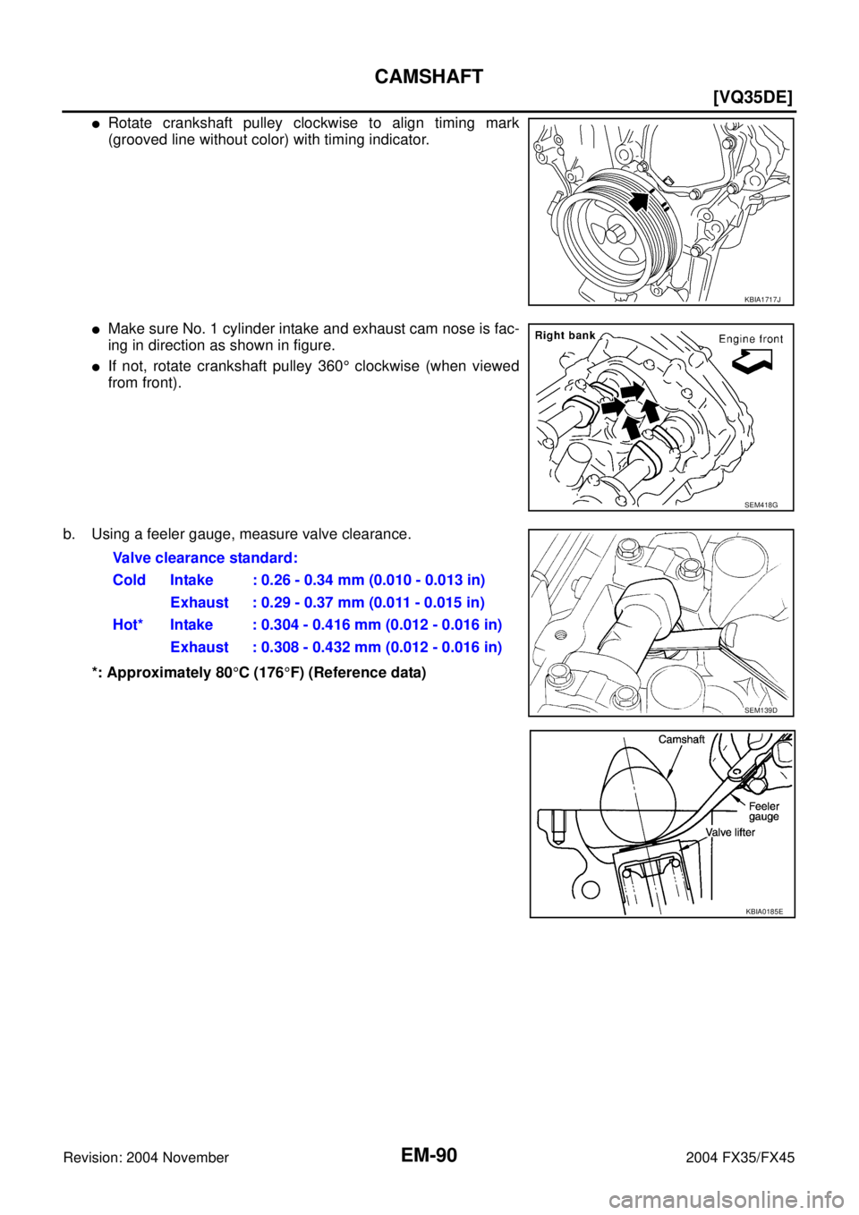
�Rotate crankshaft pulley clockwise to align timing mark
(grooved line without color) with timing indicator.
�Make sure No. 1 cylinder intake and exhaust cam nose is fac-
ing in direction as shown in figure.
�If not, rotate crankshaft pulley 360° clockwise (when viewed
from front).
b. Using a feeler gauge, measure valve clearance.
*: Approximately 80°C (176°F) (Reference data)
KBIA1717J
SEM418G
Valve clearance standard:
Cold Intake : 0.26 - 0.34 mm (0.010 - 0.013 in)
Exhaust : 0.29 - 0.37 mm (0.011 - 0.015 in)
Hot* Intake : 0.304 - 0.416 mm (0.012 - 0.016 in)
Exhaust : 0.308 - 0.432 mm (0.012 - 0.016 in)
SEM139D
KBIA0185E
![INFINITI FX35 2004 Service Manual EC-1324
[VK45DE]
EVAPORATIVE EMISSION SYSTEM
Revision: 2004 November 2004 FX35/FX45
EVAP SERVICE PORT
Positive pressure is delivered to the EVAP system through the EVAP
service port. If fuel vapor lea](/manual-img/42/57021/w960_57021-2664.png "INFINITI FX35 2004 Service Manual EC-1324
[VK45DE]
EVAPORATIVE EMISSION SYSTEM
Revision: 2004 November 2004 FX35/FX45
EVAP SERVICE PORT
Positive pressure is delivered to the EVAP system through the EVAP
service port. If fuel vapor lea")
![INFINITI FX35 2004 Service Manual TIMING CHAIN
EM-65
[VQ35DE]
C
D
E
F
G
H
I
J
K
L
MA
EM
Revision: 2004 November 2004 FX35/FX45
18. Remove collared O-ring from front timing chain case (left and
right side).
19. Remove right and left ro](/manual-img/42/57021/w960_57021-2789.png "INFINITI FX35 2004 Service Manual TIMING CHAIN
EM-65
[VQ35DE]
C
D
E
F
G
H
I
J
K
L
MA
EM
Revision: 2004 November 2004 FX35/FX45
18. Remove collared O-ring from front timing chain case (left and
right side).
19. Remove right and left ro")