Page 2816 of 4449
CAMSHAFT
EM-91
[VQ35DE]
C
D
E
F
G
H
I
J
K
L
MA
EM
Revision: 2004 November 2004 FX35/FX45
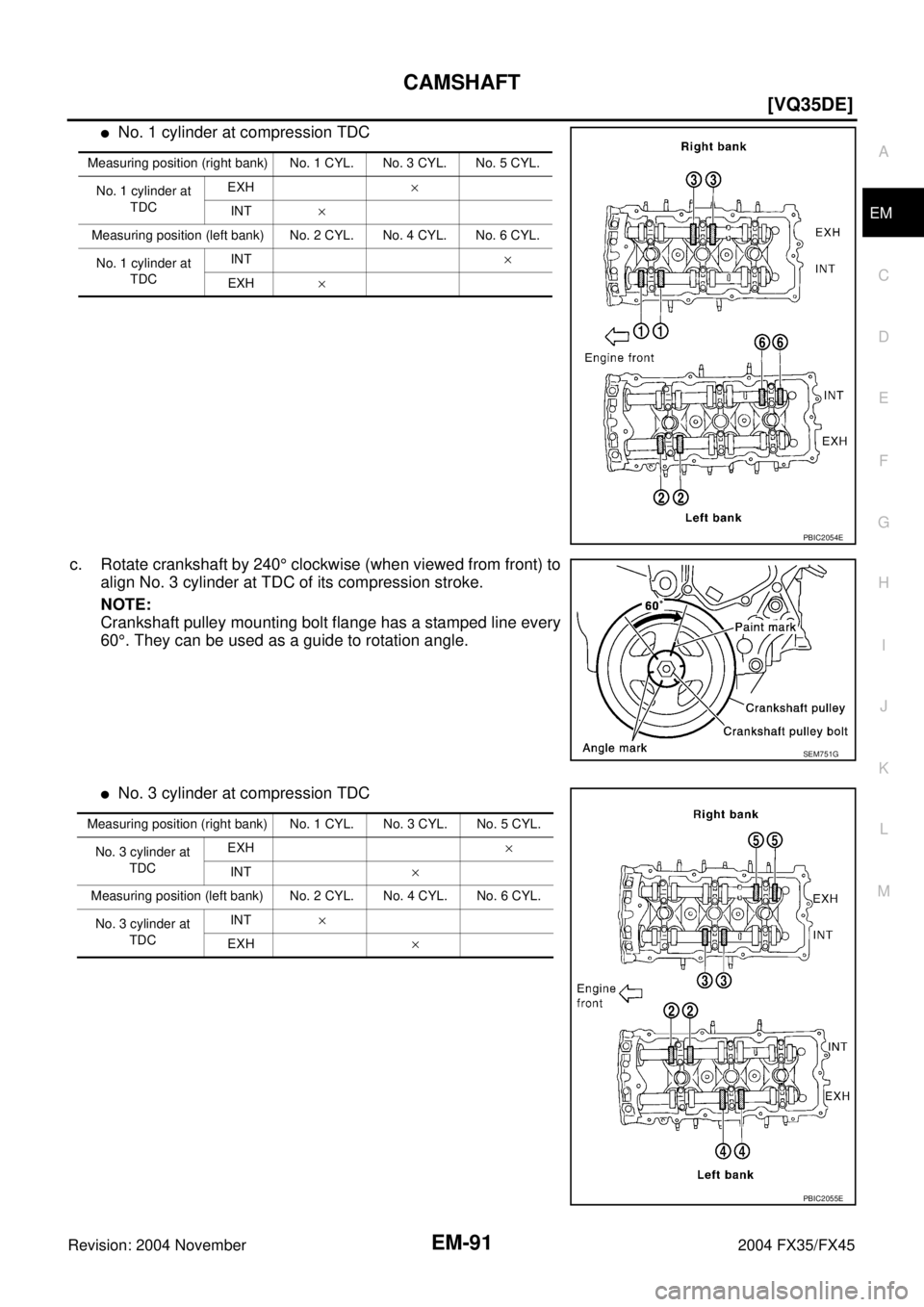
�No. 1 cylinder at compression TDC
c. Rotate crankshaft by 240° clockwise (when viewed from front) to
align No. 3 cylinder at TDC of its compression stroke.
NOTE:
Crankshaft pulley mounting bolt flange has a stamped line every
60°. They can be used as a guide to rotation angle.
�No. 3 cylinder at compression TDC
Measuring position (right bank) No. 1 CYL. No. 3 CYL. No. 5 CYL.
No. 1 cylinder at
TDCEXH×
INT×
Measuring position (left bank) No. 2 CYL. No. 4 CYL. No. 6 CYL.
No. 1 cylinder at
TDCINT×
EXH×
PBIC2054E
SEM751G
Measuring position (right bank) No. 1 CYL. No. 3 CYL. No. 5 CYL.
No. 3 cylinder at
TDCEXH×
INT×
Measuring position (left bank) No. 2 CYL. No. 4 CYL. No. 6 CYL.
No. 3 cylinder at
TDCINT×
EXH ×
PBIC2055E
Page 2817 of 4449
![INFINITI FX35 2004 Service Manual EM-92
[VQ35DE]
CAMSHAFT
Revision: 2004 November 2004 FX35/FX45
d. Rotate crankshaft by 240 degrees clockwise (when viewed from
engine front) to align No. 5 cylinder at TDC of compression
stroke.
�No](/manual-img/42/57021/w960_57021-2816.png "INFINITI FX35 2004 Service Manual EM-92
[VQ35DE]
CAMSHAFT
Revision: 2004 November 2004 FX35/FX45
d. Rotate crankshaft by 240 degrees clockwise (when viewed from
engine front) to align No. 5 cylinder at TDC of compression
stroke.
�No")
EM-92
[VQ35DE]
CAMSHAFT
Revision: 2004 November 2004 FX35/FX45
d. Rotate crankshaft by 240 degrees clockwise (when viewed from
engine front) to align No. 5 cylinder at TDC of compression
stroke.
�No. 5 cylinder at compression TDC
CAUTION:
If inspection was carried out with cold engine, make sure
values with fully warmed up engine are still within speci-
fications.
3. For measurements that are outside the specified range, perform adjustment below.
ADJUSTMENT
�Perform adjustment depending on selected head thickness of valve lifter.
�The specified valve lifter thickness is the dimension at normal temperatures. Ignore dimensional differ-
ences caused by temperature. Use the specifications for hot engine condition to adjust.
1. Remove camshaft. Refer to EM-83, "
REMOVAL" .
2. Remove valve lifters at the locations that are outside the standard.
3. Measure the center thickness of the removed valve lifters with a
micrometer.
4. Use the equation below to calculate valve lifter thickness for replacement.
SEM751G
Measuring position (right bank) No. 1 CYL. No. 3 CYL. No. 5 CYL.
No. 5 cylinder at
TDCEXH×
INT×
Measuring position (left bank) No. 2 CYL. No. 4 CYL. No. 6 CYL.
No. 5 cylinder at
TDCINT×
EXH ×
PBIC2056E
KBIA0057E
Page 2827 of 4449
![INFINITI FX35 2004 Service Manual EM-102
[VQ35DE]
CYLINDER HEAD
Revision: 2004 November 2004 FX35/FX45
d. Turn all bolts “90” degrees clockwise (angle tightening).
e. Turn all bolts “90” degrees clockwise again [target: 90 deg](/manual-img/42/57021/w960_57021-2826.png "INFINITI FX35 2004 Service Manual EM-102
[VQ35DE]
CYLINDER HEAD
Revision: 2004 November 2004 FX35/FX45
d. Turn all bolts “90” degrees clockwise (angle tightening).
e. Turn all bolts “90” degrees clockwise again [target: 90 deg")
EM-102
[VQ35DE]
CYLINDER HEAD
Revision: 2004 November 2004 FX35/FX45
d. Turn all bolts “90” degrees clockwise (angle tightening).
e. Turn all bolts “90” degrees clockwise again [target: 90 degrees
(angle tightening)].
CAUTION:
Check and confirm the tightening angle by using angle
wrench (SST) and cylinder head bolt wrench (commercial
service tool). Avoid judgment by visual inspection without
SST.
�Check tightening angle indicated on angle wrench (SST) indi-
cator plate.
4. After installing cylinder head, measure distance between front
end faces of cylinder block and cylinder head (left and right
banks).
�If measurement is outside the specified range, re-install cylin-
der head.
5. Perform steps in reverse order of removal for the following operations.
Disassembly and AssemblyABS004X9
PBIC0888E
Standard : 14.1 - 14.9 mm (0.555 - 0.587 in)
EMQ0662D
1. Valve lifter 2. Valve collet 3. Valve spring retainer
4. Valve spring 5. Valve oil seal 6. Valve spring seat
7. Valve guide 8. Spark plug 9. Spark plug tube
PBIC2308E
Page 2853 of 4449
![INFINITI FX35 2004 Service Manual EM-128
[VQ35DE]
CYLINDER BLOCK
Revision: 2004 November 2004 FX35/FX45
c. Turn all bolts another “90” degrees clockwise (Angle tightening).
CAUTION:
Use an angle wrench [SST: KV10112100 (BT8653-A)]](/manual-img/42/57021/w960_57021-2852.png "INFINITI FX35 2004 Service Manual EM-128
[VQ35DE]
CYLINDER BLOCK
Revision: 2004 November 2004 FX35/FX45
c. Turn all bolts another “90” degrees clockwise (Angle tightening).
CAUTION:
Use an angle wrench [SST: KV10112100 (BT8653-A)]")
EM-128
[VQ35DE]
CYLINDER BLOCK
Revision: 2004 November 2004 FX35/FX45
c. Turn all bolts another “90” degrees clockwise (Angle tightening).
CAUTION:
Use an angle wrench [SST: KV10112100 (BT8653-A)] to
check tightening angle. Do not make judgment by visual
inspection.
�After installing mounting bolts, make sure that crankshaft can
be rotated smoothly by hand.
�Check crankshaft end play. Refer to EM-136, "CRANKSHAFT
END PLAY" .
11. Inspect outer diameter of connecting rod bolt. Refer to EM-144,
"CONNECTING ROD BOLT OUTER DIAMETER" .
12. Install piston to connecting rod.
a. Using a snap ring pliers (commercial service tool), install a new snap ring to the groove of the piston rear
side.
�Insert it fully into groove to install.
b. Install piston to connecting rod.
�Using an industrial drier or similar tool, heat piston until piston pin can be pushed in by hand without
excess force [approx. 60 to 70 °C (140 to 158 °F)]. From the front to the rear, insert piston pin into pis-
ton and connecting rod.
�Assemble so that the front mark on the piston crown and the
cylinder number on connecting rod are positioned as shown in
the figure.
c. Install a new snap ring to the groove of the piston front side.
�Insert it fully into groove to install.
�After installing, make sure connecting rod moves smoothly.
13. Using a piston ring expander (commercial service tool), install piston rings.
CAUTION:
Be careful not to damage piston.
�If there is stamped mark on ring, mount it with marked side
up.
NOTE:
If there is no stamp on ring, no specific orientation is required
for installation.
�Position each ring with the gap as shown in the figure refer-
ring to the piston front mark.
PBIC0921E
SEM838F
Stamped mark:
To p r i n g : —
Second ring : “R”
SEM757G
PBIC0808E
Page 2854 of 4449
![INFINITI FX35 2004 Service Manual CYLINDER BLOCK
EM-129
[VQ35DE]
C
D
E
F
G
H
I
J
K
L
MA
EM
Revision: 2004 November 2004 FX35/FX45
14. Install connecting rod bearings to connecting rod and connect-
ing rod cap.
�When installing connect](/manual-img/42/57021/w960_57021-2853.png "INFINITI FX35 2004 Service Manual CYLINDER BLOCK
EM-129
[VQ35DE]
C
D
E
F
G
H
I
J
K
L
MA
EM
Revision: 2004 November 2004 FX35/FX45
14. Install connecting rod bearings to connecting rod and connect-
ing rod cap.
�When installing connect")
CYLINDER BLOCK
EM-129
[VQ35DE]
C
D
E
F
G
H
I
J
K
L
MA
EM
Revision: 2004 November 2004 FX35/FX45
14. Install connecting rod bearings to connecting rod and connect-
ing rod cap.
�When installing connecting rod bearings, apply engine oil to
the bearing surface (inside). Do not apply engine oil to the
back surface, but thoroughly clean it.
�When installing, align connecting rod bearing stopper protru-
sion with the cutout of connecting rod to install.
�Check the oil hole on connecting rod and that on the corre-
sponding bearing are aligned.
15. Install piston and connecting rod assembly to crankshaft.
�Position crankshaft pin corresponding to connecting rod to be
installed onto the bottom dead center.
�Apply engine oil sufficiently to cylinder bore, piston and crank-
shaft pin.
�Match cylinder position with the cylinder number on connect-
ing rod to install.
�Using a piston ring compressor (SST) or suitable tool, install
piston with the front mark on the piston crown facing the front
of engine.
CAUTION:
Be careful not to damage cylinder wall and crankshaft pin, resulting from an interference of con-
necting rod big end.
16. Install connecting rod cap.
�Match the stamped cylinder number marks on connecting rod
with those on cap to install.
�Be sure that front mark on connecting rod cap is facing front
of engine.
17. Tighten connecting rod bolt as follows.
a. Apply engine oil to the threads and seats of connecting rod
bolts.
b. Tighten bolts.
c. Then tighten all bolts “90” degrees clockwise (Angle tightening).
CAUTION:
Always use an angle wrench [SST: KV10112100 (BT8653-
A)]. Avoid tightening based on visual check alone.
�After tightening bolt, make sure that the crankshaft rotates
smoothly.
�Check the connecting rod side clearance. Refer to EM-136, "CONNECTING ROD SIDE CLEARANCE"
18. Install baffle plate to main bearing beam.
PBIC0266E
SEM620
PBIC0809E
: 19.6 N·m (2.0 kg-m, 14 ft-lb)
SEM953E
Page 2923 of 4449
![INFINITI FX35 2004 Service Manual EM-198
[VK45DE]
TIMING CHAIN
Revision: 2004 November 2004 FX35/FX45
5. Remove intake valve timing control cover as follows:
a. Loosen and remove mounting bolts in the reverse order as
shown in the fi](/manual-img/42/57021/w960_57021-2922.png "INFINITI FX35 2004 Service Manual EM-198
[VK45DE]
TIMING CHAIN
Revision: 2004 November 2004 FX35/FX45
5. Remove intake valve timing control cover as follows:
a. Loosen and remove mounting bolts in the reverse order as
shown in the fi")
EM-198
[VK45DE]
TIMING CHAIN
Revision: 2004 November 2004 FX35/FX45
5. Remove intake valve timing control cover as follows:
a. Loosen and remove mounting bolts in the reverse order as
shown in the figure.
b . U s e s e a l c u t t e r [ S S T: K V 1 0 1111 0 0 ( J 3 7 2 2 8 ) ] o r e q u i v a l e n t t o o l
to cut liquid gasket for removal.
CAUTION:
�Exercise care not to damage mating surfaces.
�Pull out cover keeping levelness without an angle, as
inner part of cover is engaged with the center of camshaft
sprocket (INT).
6. Remove O-rings from front cover.
7. Obtain No. 1 cylinder at TDC of its compression stroke as follows:
a. Rotate crankshaft pulley clockwise to align the TDC identifica-
tion notch (without paint mark) with timing indicator on front
cover.
b. Make sure that both intake and exhaust cam noses of No. 1 cyl-
inder (engine front side of left bank) are located as shown in the
figure.
�If not, turn crankshaft pulley one revolution (360 degrees) and
align as shown in the figure.
8. Remove crankshaft pulley as follows:
PBIC0051E
SBIA0374E
PBIC2341E
KBIA0400J
Page 2932 of 4449
![INFINITI FX35 2004 Service Manual TIMING CHAIN
EM-207
[VK45DE]
C
D
E
F
G
H
I
J
K
L
MA
EM
Revision: 2004 November 2004 FX35/FX45
f. Further tighten by 90 degrees. (Angle tightening)
�Check the tightening angle by referencing to the not](/manual-img/42/57021/w960_57021-2931.png "INFINITI FX35 2004 Service Manual TIMING CHAIN
EM-207
[VK45DE]
C
D
E
F
G
H
I
J
K
L
MA
EM
Revision: 2004 November 2004 FX35/FX45
f. Further tighten by 90 degrees. (Angle tightening)
�Check the tightening angle by referencing to the not")
TIMING CHAIN
EM-207
[VK45DE]
C
D
E
F
G
H
I
J
K
L
MA
EM
Revision: 2004 November 2004 FX35/FX45
f. Further tighten by 90 degrees. (Angle tightening)
�Check the tightening angle by referencing to the notches. The
angle between two notches is 90 degrees.
15. Rotate crankshaft pulley in normal direction (clockwise when viewed from engine front) to confirm it turns
smoothly.
16. Install in the reverse order of removal after this step.
NOTE:
If hydraulic pressure inside timing chain tensioner drops after removal/installation, slack in guide may gen-
erate a pounding noise during and just after engine start. However, this does not indicate an unusualness.
Noise will stop after hydraulic pressure rises.
INSPECTION AFTER INSTALLATION
�Before starting engine, check the levels of engine coolant, lubrications and working fluid. If less than
required quantity, fill to the specified level.
�Run engine to check for unusual noise and vibration.
�Warm up engine thoroughly to make sure there is no leakage of engine coolant, engine oil and working
fluid, fuel and exhaust gas.
�Bleed air from passages in pipes and tubes of applicable lines, such as in cooling system.
�After cooling down engine, again check amounts of engine coolant, engine oil and working fluid. Refill to
specified level, if necessary.
Summary of the inspection items:
PBIC2346E
Item Before starting engine Engine running After engine stopped
Engine coolant Level Leakage Level
Engine oil Level Leakage Level
Working fluid Level Leakage Level
Page 2940 of 4449
CAMSHAFT
EM-215
[VK45DE]
C
D
E
F
G
H
I
J
K
L
MA
EM
Revision: 2004 November 2004 FX35/FX45
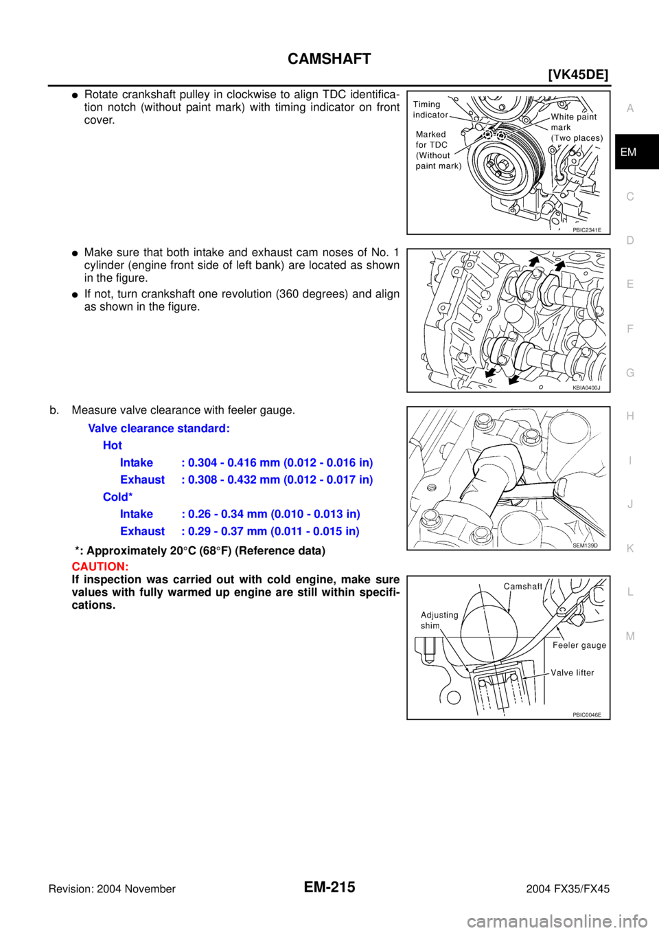
�Rotate crankshaft pulley in clockwise to align TDC identifica-
tion notch (without paint mark) with timing indicator on front
cover.
�Make sure that both intake and exhaust cam noses of No. 1
cylinder (engine front side of left bank) are located as shown
in the figure.
�If not, turn crankshaft one revolution (360 degrees) and align
as shown in the figure.
b. Measure valve clearance with feeler gauge.
*: Approximately 20°C (68°F) (Reference data)
CAUTION:
If inspection was carried out with cold engine, make sure
values with fully warmed up engine are still within specifi-
cations.
PBIC2341E
KBIA0400J
Valve clearance standard:
Hot
Intake : 0.304 - 0.416 mm (0.012 - 0.016 in)
Exhaust : 0.308 - 0.432 mm (0.012 - 0.017 in)
Cold*
Intake : 0.26 - 0.34 mm (0.010 - 0.013 in)
Exhaust : 0.29 - 0.37 mm (0.011 - 0.015 in)
SEM139D
PBIC0046E