2004 INFINITI FX35 homelink
[x] Cancel search: homelinkPage 811 of 4449

BL-4Revision: 2004 November 2004 FX35/FX45Diagnostic Procedure 5 ........................................205
VEHICLE SECURITY HEADLAMP ALARM
CHECK ..............................................................205
Diagnostic Procedure 6 ........................................205
DOOR LOCK AND UNLOCK SWITCH CHECK .205
IVIS (INFINITI VEHICLE IMMOBILIZER SYSTEM-
NATS) ......................................................................206
Component Parts and Harness Connector Location .206
System Description ...............................................206
DESCRIPTION ..................................................206
SECURITY INDICATOR ....................................207
System Composition .............................................208
ECM Re-communicating Function ........................208
Wiring Diagram – NATS – .....................................209
MODELS WITH INTELLIGENT KEY SYSTEM . 209
MODELS WITHOUT INTELLIGENT KEY SYS-
TEM ...................................................................211
Terminals and Reference Value for Steering Lock
Unit/with Intelligent Key System ...........................212
Terminals and Reference Value for Intelligent Key
Unit/with Intelligent Key System ...........................212
Terminals and Reference Value for BCM ..............213
CONSULT-II ..........................................................214
CONSULT-II INSPECTION PROCEDURE ........214
CONSULT-II DIAGNOSTIC TEST MODE FUNC-
TION ..................................................................215
HOW TO READ SELF-DIAGNOSTIC RESULTS .215
NATS SELF-DIAGNOSTIC RESULT ITEM
CHART ..............................................................216
Diagnosis Procedure ............................................217
WORK FLOW ....................................................217
Trouble Diagnosis Symptom Chart .......................218
Security Indicator Inspection ................................218
Diagnostic Procedure 1 ........................................219
Diagnostic Procedure 2 ........................................220
Diagnostic Procedure 3 ........................................221
Diagnostic Procedure 4 ........................................222
Diagnostic Procedure 5 ........................................223
Diagnostic Procedure 6 ........................................224
Diagnostic Procedure 7 ........................................226
Removal and Installation NATS Antenna Amp. ....227
REMOVAL .........................................................227
INSTALLATION ..................................................227
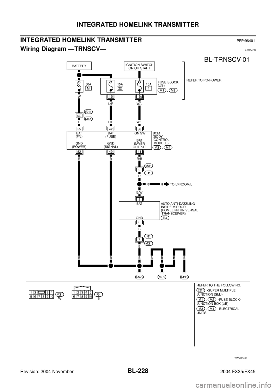
INTEGRATED HOMELINK TRANSMITTER ...........228Wiring Diagram —TRNSCV— ..............................228
Trouble Diagnoses ................................................229
DIAGNOSTIC PROCEDURE .............................229
BODY REPAIR ........................................................231
Body Exterior Paint Color ......................................231
Body Component Parts .........................................232
UNDERBODY COMPONENT PARTS ...............232
BODY COMPONENT PARTS ............................234
Corrosion Protection .............................................236
DESCRIPTION ..................................................236
ANTI-CORROSIVE WAX ...................................237
UNDERCOATING ..............................................238
STONE GUARD COAT ......................................239
Body Sealing .........................................................240
DESCRIPTION ..................................................240
Body Construction .................................................243
BODY CONSTRUCTION ...................................243
Body Alignment .....................................................244
BODY CENTER MARKS ...................................244
PANEL PARTS MATCHING MARKS .................245
DESCRIPTION ..................................................246
ENGINE COMPARTMENT ................................247
UNDERBODY ....................................................249
PASSENGER COMPARTMENT ........................251
REAR BODY ......................................................253
Handling Precautions For Plastics ........................255
HANDLING PRECAUTIONS FOR PLASTICS ..255
LOCATION OF PLASTIC PARTS ......................256
Precautions In Repairing High Strength Steel .......258
HIGH STRENGTH STEEL (HSS) USED IN NIS-
SAN VEHICLES .................................................258
Replacement Operations ......................................261
DESCRIPTION ..................................................261
HOODLEDGE ....................................................264
FRONT SIDE MEMBER ....................................266
FRONT SIDE MEMBER (PARTIAL REPLACE-
MENT) ................................................................268
FRONT PILLAR .................................................270
CENTER PILLAR ...............................................272
OUTER SILL ......................................................274
REAR FENDER .................................................276
REAR PANEL ....................................................278
REAR END CROSSMEMBER ...........................280
REAR FLOOR REAR .........................................282
REAR SIDE MEMBER EXTENSION .................285
Page 1035 of 4449

BL-228
INTEGRATED HOMELINK TRANSMITTER
Revision: 2004 November 2004 FX35/FX45
INTEGRATED HOMELINK TRANSMITTERPFP:96401
Wiring Diagram —TRNSCV—AIS004PU
TIWM0340E
Page 1036 of 4449

INTEGRATED HOMELINK TRANSMITTER
BL-229
C
D
E
F
G
H
J
K
L
MA
B
BL
Revision: 2004 November 2004 FX35/FX45
Trouble DiagnosesAIS004PV
DIAGNOSTIC PROCEDURE
SYMPTOM: Transmitter Does Not Activate Receiver.
Before conducting the procedure given below, make sure that system receiver (garage door opener, etc.)
operates with original, hand-held transmitter. If NG, receiver or hand-held transmitter is malfunctioning, not
vehicle related.
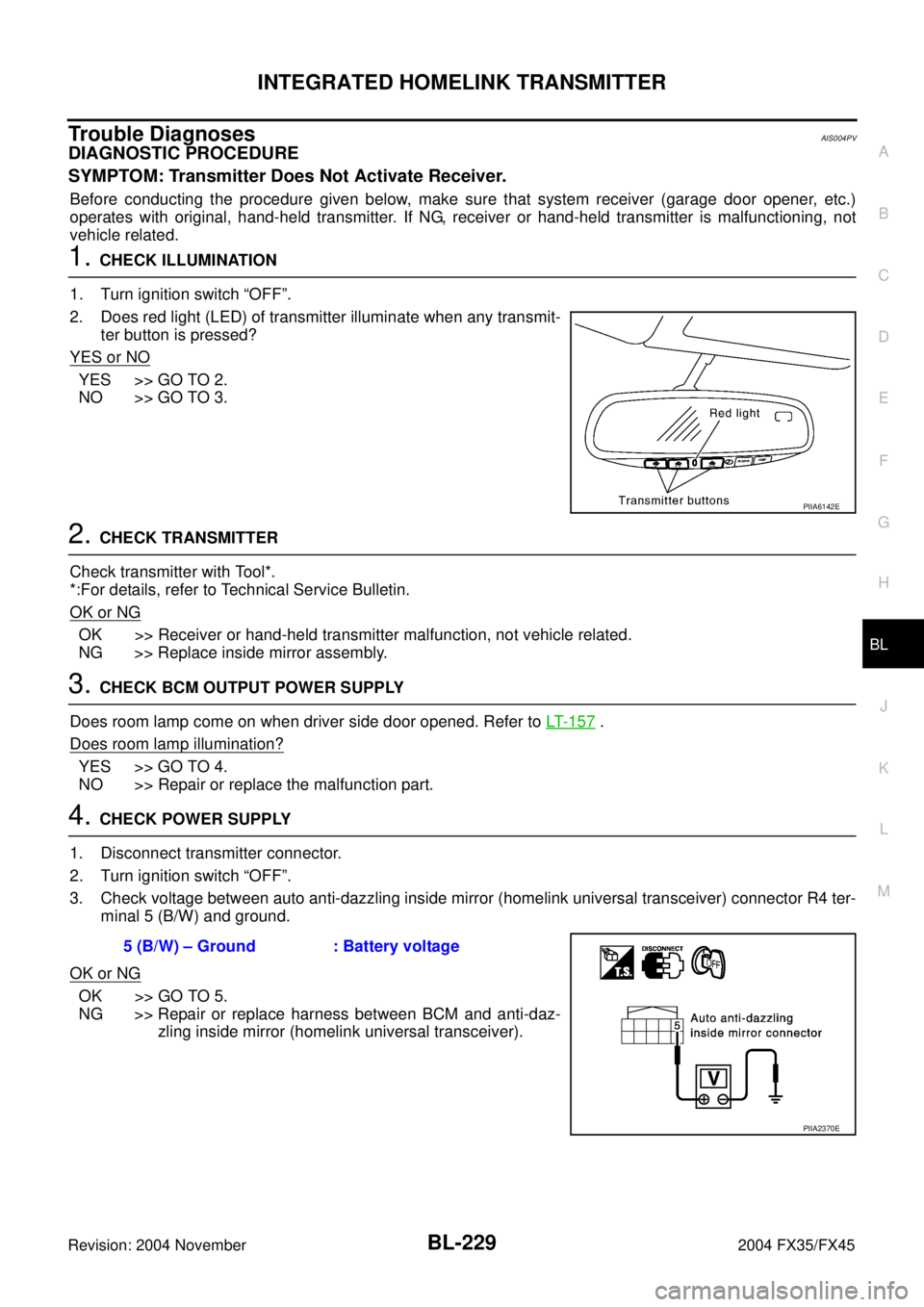
1. CHECK ILLUMINATION
1. Turn ignition switch “OFF”.
2. Does red light (LED) of transmitter illuminate when any transmit-
ter button is pressed?
YES or NO
YES >> GO TO 2.
NO >> GO TO 3.
2. CHECK TRANSMITTER
Check transmitter with Tool*.
*:For details, refer to Technical Service Bulletin.
OK or NG
OK >> Receiver or hand-held transmitter malfunction, not vehicle related.
NG >> Replace inside mirror assembly.
3. CHECK BCM OUTPUT POWER SUPPLY
Does room lamp come on when driver side door opened. Refer to LT- 1 5 7
.
Does room lamp illumination?
YES >> GO TO 4.
NO >> Repair or replace the malfunction part.
4. CHECK POWER SUPPLY
1. Disconnect transmitter connector.
2. Turn ignition switch “OFF”.
3. Check voltage between auto anti-dazzling inside mirror (homelink universal transceiver) connector R4 ter-
minal 5 (B/W) and ground.
OK or NG
OK >> GO TO 5.
NG >> Repair or replace harness between BCM and anti-daz-
zling inside mirror (homelink universal transceiver).
PIIA6142E
5 (B/W) – Ground : Battery voltage
PIIA2370E
Page 1037 of 4449

BL-230
INTEGRATED HOMELINK TRANSMITTER
Revision: 2004 November 2004 FX35/FX45
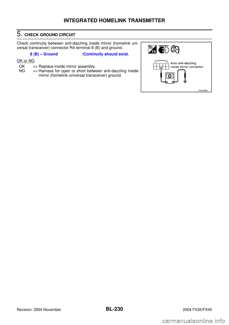
5. CHECK GROUND CIRCUIT
Check continuity between anti-dazzling inside mirror (homelink uni-
versal transceiver) connector R4 terminal 8 (B) and ground.
OK or NG
OK >> Replace inside mirror assembly.
NG >> Harness for open or short between anti-dazzling inside
mirror (homelink universal transceiver) ground. 8 (B) – Ground :Continuity should exist.
PIIA2368E
Page 3278 of 4449

IDX-5
A
C
D
E
F
G
H
I
J
K
L B
IDX
ALPHABETICAL INDEX
LT-73
Headlining - See Roof trim .................................. EI-42
Heated oxygen sensor 1 (bank 1) .... EC-205, EC-214,
EC-226
, EC-433, EC-439, EC-863, EC-872, EC-884,
EC-1103
, EC-1109
Heated oxygen sensor 1 (bank 2) .... EC-205, EC-214,
EC-226
, EC-433, EC-439, EC-863, EC-872, EC-884,
EC-1103
, EC-1109
Heated oxygen sensor 1 heater (bank 1) ....... EC-149,
EC-806
Heated oxygen sensor 1 heater (bank 2) ....... EC-149,
EC-806
Heated oxygen sensor 2 (bank 1) .... EC-236, EC-245,
EC-446
, EC-457, EC-894, EC-903, EC-1116, EC-1127
Heated oxygen sensor 2 (bank 2) .... EC-236, EC-245,
EC-446
, EC-457, EC-894, EC-903, EC-1116, EC-1127
Heated oxygen sensor 2 heater (bank 1) ....... EC-157,
EC-814
Heated oxygen sensor 2 heater (bank 2) ....... EC-157,
EC-814
Heated seat ....................................................... SE-98
Heater and cooling unit (Heater core) ........... ATC-126
HFC134a (R134a) system precaution ............... ATC-5
HFC134a (R134a) system service procedure ATC-137
HFC134a (R134a) system service tools .......... ATC-18
HFC134a system service equipment precaution ..........
ATC-13
High & low reverse clutch solenoid valve ....... AT-164,
AT-166
Hood ................................................................... BL-14
Horn ................................................................. WW-56
HORN - Wiring diagram ................................... WW-56
HSEAT - Wiring diagram ................................... SE-99
I
IATS - Wiring diagram ....................... EC-182
, EC-839
ICC - Wiring diagram ....................................... ACS-20
ICC/BS - Wiring diagram ................. EC-524, EC-1191
ICC/SW - Wiring diagram ................ EC-510, EC-1176
ICCBOF - Wiring diagram ................ EC-616, EC-1294
Idle air volume learning ....................... EC-49, EC-698
Idle mixture ratio .................................. EC-38, EC-687
Idle speed ............................................ EC-38, EC-687
Idle speed control (ISC) .... EC-392, EC-394, EC-1048,
EC-1050
Ignition coil ....................................... EC-585, EC-1262
Ignition coil(VK45DE) ...................................... EM-185
Ignition coil(VQ35DE) ........................................ EM-42
Ignition control system ..................... EC-585, EC-1262
Ignition key hole illumination ............................. LT-153
Ignition timing ...................................... EC-38, EC-687
IGNSYS - Wiring diagram ................ EC-586, EC-1263
Illumination control ............................................ LT-197
In vehicle sensor ........................... ATC-107, ATC-118
INF/D - Wring diagram ....................................... AV-63
INJECT - Wiring diagram ................. EC-598, EC-1275
Injector ............................................. EC-597, EC-1274
Input clutch solenoid valve ................. AT-152, AT-154
Instrument panel ................................................. IP-10
Intake air temperature sensor ........... EC-180, EC-200,
EC-837
, EC-858
Intake door control linkage adjustment ............ ATC-78
Intake door motor ............................ ATC-76, ATC-124
Intake manifold(VK45DE) ............................... EM-174
Intake manifold(VQ35DE) ................................. EM-24
Intake sensor ................................ ATC-113, ATC-120
Intake valve timing control (Bank 1) ... EC-145, EC-795
Intake valve timing control (Bank 2) ... EC-145, EC-795
Intake valve timing control position sensor (Bank 1) ....
EC-1095
Intake valve timing control position sensor (Bank 2) ....
EC-1095
Intake valve timing control solenoid valve (Bank 1) ......
EC-408
, EC-1070
Intake valve timing control solenoid valve (Bank 2) ......
EC-408
, EC-1070
Integrated homelink transmitter ....................... BL-228
Intelligent cruise control (ICC) system .............. ACS-6
Interior ................................................................. EI-37
Interior lamp ...................................................... LT-157
IPDM (Intelligent power distribution module engine
room) ................................................................. PG-18
IVCB1 - Wiring diagram .... EC-409, EC-798, EC-1071
IVCB2 - Wiring diagram .... EC-411, EC-800, EC-1073
IVCSB1 - Wiring diagram ............................... EC-1096
IVCSB2 - Wiring diagram ............................... EC-1098
IVIS (Infiniti vehicle immobilizer system) precautions ...
GI-3
J
Joint connector (J/C) .......................................... PG-76
K
Knock sensor (KS) ............................. EC-297
, EC-955
KS - Wiring diagram ........................... EC-298, EC-956
L
LAN system circuit ........................................... ATC-66
Laser beam aiming adjustment ....................... ACS-12
Latch (lower anchors and tether for children) system ...
SB-11
Line pressure solenoid valve ........................... AT-127
Line pressure test (A/T) ..................................... AT-52
Liquid gasket application ................................... LU-21
Liquid gasket application(VQ35DE) EM-6, LU-3, CO-3
Location of electrical units ................................. PG-70
Low coast brake solenoid valve ......... AT-168, AT-170
Low tire pressure warning system ...................... WT-7
Lubricant (R134a) A/C ........................ ATC-7, ATC-27
Lubrication circuit (engine)(VK45DE) ................ LU-23
Lubrication circuit (engine)(VQ35DE) .................. LU-5
Lubrication oil A/C .......................................... ATC-161
Page 3904 of 4449

HARNESS
PG-69
C
D
E
F
G
H
I
J
L
MA
B
PG
Revision: 2004 November 2004 FX35/FX45
PHASE EC Camshaft Position Sensor (PHASE)
PHSB1 EC Camshaft Position Sensor (PHASE) (Bank1)
PHSB2 EC Camshaft Position Sensor (PHASE) (Bank2)
PNP/SW AT Park / Neutral Position Switch
PNP/SW EC Park / Neutral Position Switch
POS EC Crankshaft Position Sensor (CKPS) (POS)
POWER AT Transmission Control Module Power Supply
POWER PG Power Supply Routing
PRE/SE EC Evap Control System Pressure Sensor
PS/SEN EC Power Steering Pressure Sensor
R/VIEW DI Rear View Camera Control System
ROOM/L LT Interior Room Lamp
RP/SEN EC Refrigerant Pressure Sensor
SEAT SE Power Seat
SEN/PW EC Sensor Power Supply
SHIFT AT A/T Shift Lock System
SROOF RF Sunroof
SRS SRS Supplemental Restraint System
START SC Starting System
STOP/L LT Stop Lamp
STSIG AT Start Signal Circuit
T/WARN WT Low Tire Pressure Warning System
TAIL/L LT Parking, License and Tail Lamps
TPS1 EC Throttle Position Sensor (Sensor 1)
TPS2 EC Throttle Position Sensor (Sensor 2)
TPS3 EC Throttle Position Sensor
TRNSCV BL Homelink Universal Transceiver
TURN LT Turn Signal and Hazard Warning Lamp
VDC BRC Vehicle Dynamics Control System
VEHSEC BL Vehicle Security System
VENT/V EC Evap Canister Vent Control Valve
VIAS/V EC VIAS Control Solenoid Valve
VSSA/T AT Vehicle Speed Sensor A/T (Revolution Sensor)
WARN DI Warning Lamps
WINDOW GW Power Window
WIP/R WW Rear Wiper and Washer
WIPER WW Front Wiper and Washer Code Section Wiring Diagram Name