Page 727 of 4449
AV-136
NAVIGATION SYSTEM
Revision: 2004 November 2004 FX35/FX45
Confirmation/Adjustment ModeAKS00BN5
OPERATION PROCEDURE
1. Start the engine.
2. Turn the audio system off.
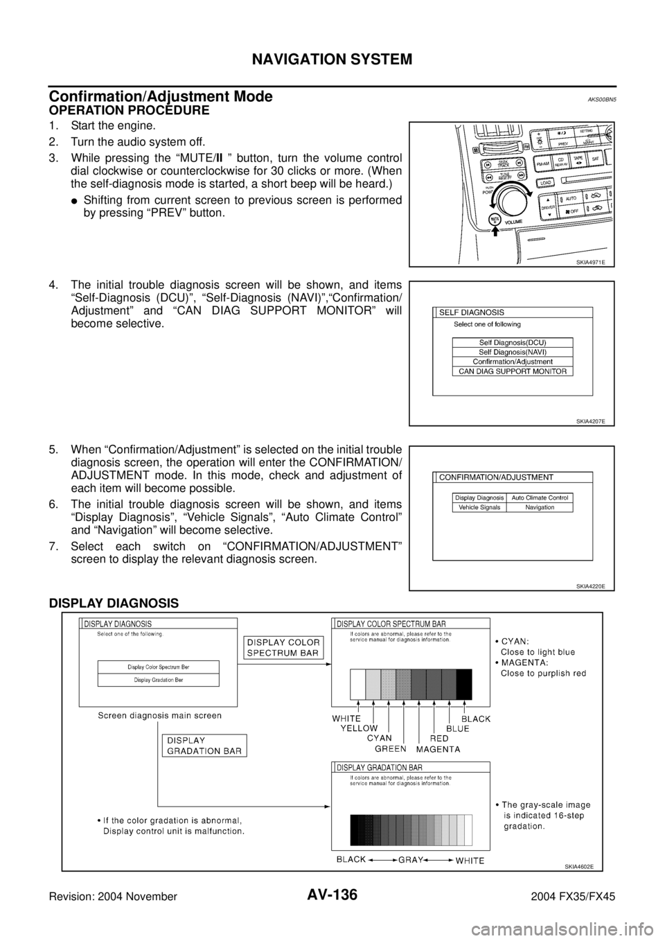
3. While pressing the “MUTE/II ” button, turn the volume control
dial clockwise or counterclockwise for 30 clicks or more. (When
the self-diagnosis mode is started, a short beep will be heard.)
�Shifting from current screen to previous screen is performed
by pressing “PREV” button.
4. The initial trouble diagnosis screen will be shown, and items
“Self-Diagnosis (DCU)”, “Self-Diagnosis (NAVI)”,“Confirmation/
Adjustment” and “CAN DIAG SUPPORT MONITOR” will
become selective.
5. When “Confirmation/Adjustment” is selected on the initial trouble
diagnosis screen, the operation will enter the CONFIRMATION/
ADJUSTMENT mode. In this mode, check and adjustment of
each item will become possible.
6. The initial trouble diagnosis screen will be shown, and items
“Display Diagnosis”, “Vehicle Signals”, “Auto Climate Control”
and “Navigation” will become selective.
7. Select each switch on “CONFIRMATION/ADJUSTMENT”
screen to display the relevant diagnosis screen.
DISPLAY DIAGNOSIS
SKIA4971E
SKIA4207E
SKIA4220E
SKIA4602E
Page 734 of 4449
NAVIGATION SYSTEM
AV-143
C
D
E
F
G
H
I
J
L
MA
B
AV
Revision: 2004 November 2004 FX35/FX45
Can Diag Support MonitorAKS007J3
OPERATION PROCEDURE
1. Start the engine.
2. Turn the audio system off.
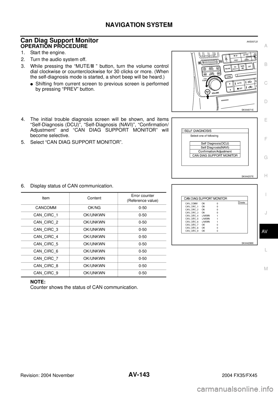
3. While pressing the “MUTE/II ” button, turn the volume control
dial clockwise or counterclockwise for 30 clicks or more. (When
the self-diagnosis mode is started, a short beep will be heard.)
�Shifting from current screen to previous screen is performed
by pressing “PREV” button.
4. The initial trouble diagnosis screen will be shown, and items
“Self-Diagnosis (DCU)”, “Self-Diagnosis (NAVI)”, “Confirmation/
Adjustment” and “CAN DIAG SUPPORT MONITOR” will
become selective.
5. Select “CAN DIAG SUPPORT MONITOR”.
6. Display status of CAN communication.
NOTE:
Counter shows the status of CAN communication.
SKIA4971E
SKIA4207E
Item ContentError counter
(Reference value)
CANCOMM OK/NG 0-50
CAN_CIRC_1 OK/UNKWN 0-50
CAN_CIRC_2 OK/UNKWN 0-50
CAN_CIRC_3 OK/UNKWN 0-50
CAN_CIRC_4 OK/UNKWN 0-50
CAN_CIRC_5 OK/UNKWN 0-50
CAN_CIRC_6 OK/UNKWN 0-50
CAN_CIRC_7 OK/UNKWN 0-50
CAN_CIRC_8 OK/UNKWN 0-50
CAN_CIRC_9 OK/UNKWN 0-50
SKIA4288E
Page 735 of 4449

AV-144
NAVIGATION SYSTEM
Revision: 2004 November 2004 FX35/FX45
A/C and AV Switch Self-Diagnosis FunctionAKS00BN6
DESCRIPTION
It can check ON/OFF operation of each switch in the A/C and AV switch and diagnose the input signals to the
steering switch (audio).
Starting the SELF-DIAGNOSIS MODE
1. Turn ignition switch from OFF to ACC.
2. Within 10 seconds press and hold the witches “MUTE/II ” and
“PREV” simultaneously for 3 seconds.
Diagnosis Function
�It can illuminate all the indicators (LED) in the A/C and AV switch.
�It can check for continuity of the switches by sounding the buzzer when the A/C and AV switch is pressed.
�It can check for continuity of harness between A/C and AV switch and steering switch (audio).
NOTE:
�Indicators (LED) of REC/FRE switch change to “FRE” → “REC” → “FRE” every time the REC/FRE switch
is pushed. (These two do not turn on at a time.)
�Impossible to check rear window defogger switch operation (No beep sound even under normal status).
Exiting the SELF-DIAGNOSIS MODE
�Turn ignition switch OFF.
SKIB0314E
Page 745 of 4449
AV-154
NAVIGATION SYSTEM
Revision: 2004 November 2004 FX35/FX45
2. CHECK HARNESS
1. Turn ignition switch OFF.
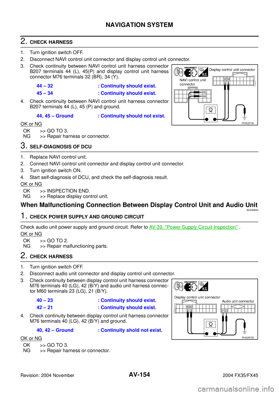
2. Disconnect NAVI control unit connector and display control unit connector.
3. Check continuity between NAVI control unit harness connector
B207 terminals 44 (L), 45(P) and display control unit harness
connector M76 terminals 32 (BR), 34 (Y).
4. Check continuity between NAVI control unit harness connector
B207 terminals 44 (L), 45 (P) and ground.
OK or NG
OK >> GO TO 3.
NG >> Repair harness or connector.
3. SELF-DIAGNOSIS OF DCU
1. Replace NAVI control unit.
2. Connect NAVI control unit connector and display control unit connector.
3. Turn ignition switch ON.
4. Start self-diagnosis of DCU, and check the self-diagnosis result.
OK or NG
OK >> INSPECTION END.
NG >> Replace display control unit.
When Malfunctioning Connection Between Display Control Unit and Audio UnitAKS00BNK
1. CHECK POWER SUPPLY AND GROUND CIRCUIT
Check audio unit power supply and ground circuit. Refer to AV- 3 9 , "
Power Supply Circuit Inspection" .
OK or NG
OK >> GO TO 2.
NG >> Repair malfunctioning parts.
2. CHECK HARNESS
1. Turn ignition switch OFF.
2. Disconnect audio unit connector and display control unit connector.
3. Check continuity between display control unit harness connector
M76 terminals 40 (LG), 42 (B/Y) and audio unit harness connec-
tor M60 terminals 23 (LG), 21 (B/Y).
4. Check continuity between display control unit harness connector
M76 terminals 40 (LG), 42 (B/Y) and ground.
OK or NG
OK >> GO TO 3.
NG >> Repair harness or connector.44 – 32 : Continuity should exist.
45 – 34 : Continuity should exist.
44, 45 – Ground : Continuity should not exist.
PKIA2873E
40 – 23 : Continuity should exist.
42 – 21 : Continuity should exist.
40, 42 – Ground : Continuity shold not exist.
PKIA2875E
Page 746 of 4449
NAVIGATION SYSTEM
AV-155
C
D
E
F
G
H
I
J
L
MA
B
AV
Revision: 2004 November 2004 FX35/FX45
3. CHECK AUDIO UNIT
1. Connect audio unit connector.
2. Turn ignition switch ON.
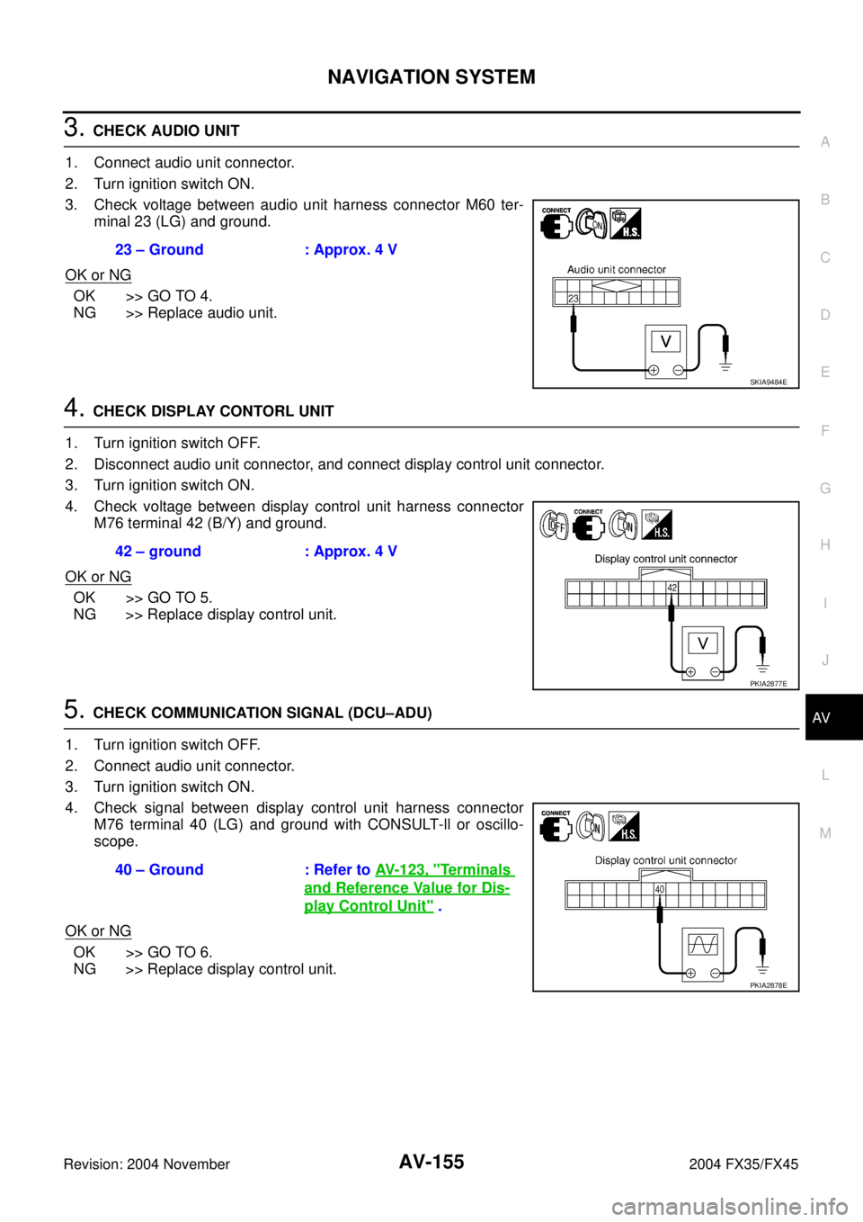
3. Check voltage between audio unit harness connector M60 ter-
minal 23 (LG) and ground.
OK or NG
OK >> GO TO 4.
NG >> Replace audio unit.
4. CHECK DISPLAY CONTORL UNIT
1. Turn ignition switch OFF.
2. Disconnect audio unit connector, and connect display control unit connector.
3. Turn ignition switch ON.
4. Check voltage between display control unit harness connector
M76 terminal 42 (B/Y) and ground.
OK or NG
OK >> GO TO 5.
NG >> Replace display control unit.
5. CHECK COMMUNICATION SIGNAL (DCU–ADU)
1. Turn ignition switch OFF.
2. Connect audio unit connector.
3. Turn ignition switch ON.
4. Check signal between display control unit harness connector
M76 terminal 40 (LG) and ground with CONSULT-ll or oscillo-
scope.
OK or NG
OK >> GO TO 6.
NG >> Replace display control unit.23 – Ground : Approx. 4 V
SKIA9484E
42 – ground : Approx. 4 V
PKIA2877E
40 – Ground : Refer to AV- 1 2 3 , "Te r m i n a l s
and Reference Value for Dis-
play Control Unit" .
PKIA2878E
Page 747 of 4449
AV-156
NAVIGATION SYSTEM
Revision: 2004 November 2004 FX35/FX45
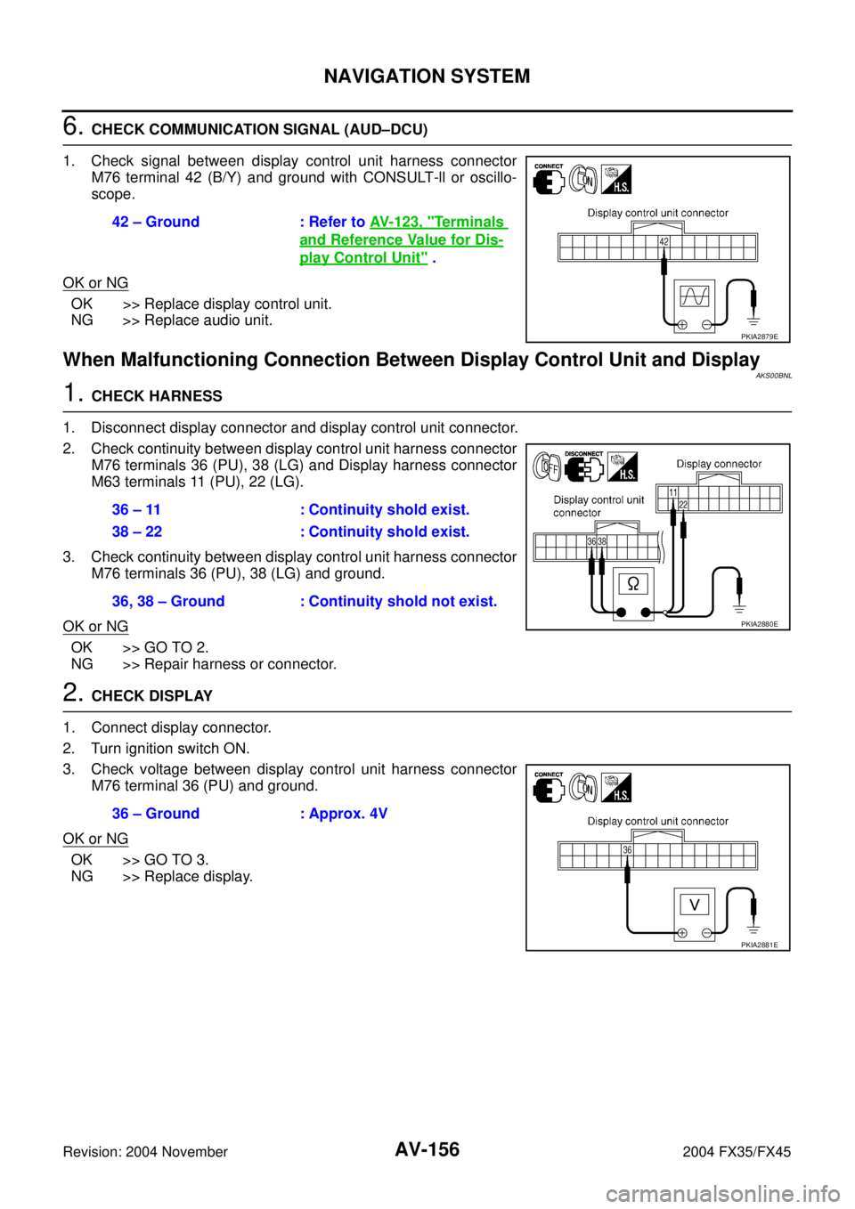
6. CHECK COMMUNICATION SIGNAL (AUD–DCU)
1. Check signal between display control unit harness connector
M76 terminal 42 (B/Y) and ground with CONSULT-ll or oscillo-
scope.
OK or NG
OK >> Replace display control unit.
NG >> Replace audio unit.
When Malfunctioning Connection Between Display Control Unit and Display AKS00BNL
1. CHECK HARNESS
1. Disconnect display connector and display control unit connector.
2. Check continuity between display control unit harness connector
M76 terminals 36 (PU), 38 (LG) and Display harness connector
M63 terminals 11 (PU), 22 (LG).
3. Check continuity between display control unit harness connector
M76 terminals 36 (PU), 38 (LG) and ground.
OK or NG
OK >> GO TO 2.
NG >> Repair harness or connector.
2. CHECK DISPLAY
1. Connect display connector.
2. Turn ignition switch ON.
3. Check voltage between display control unit harness connector
M76 terminal 36 (PU) and ground.
OK or NG
OK >> GO TO 3.
NG >> Replace display.42 – Ground : Refer to AV- 1 2 3 , "
Terminals
and Reference Value for Dis-
play Control Unit" .
PKIA2879E
36 – 11 : Continuity shold exist.
38 – 22 : Continuity shold exist.
36, 38 – Ground : Continuity shold not exist.
PKIA2880E
36 – Ground : Approx. 4V
PKIA2881E
Page 758 of 4449

NAVIGATION SYSTEM
AV-167
C
D
E
F
G
H
I
J
L
MA
B
AV
Revision: 2004 November 2004 FX35/FX45
Guide Sound is Not HeardAKS00BP7
1. CHECK VOICE GUIDE SETTING
�While driving in the dark pink route, voice guide does not operate. (note)
�Is volume setting not switched ON?
NOTE:
Voice guide is only available at intersections that satisfy certain conditions (indicated by
� on the map). There-
fore, guidance may not be given even when the route on the map changes direction.
YES or NO
YES >> GO TO 2.
NO >> Switch the setting ON and turn the volume up.
2. CHECK HARNESS
1. Turn ignition switch OFF.
2. Disconnect NAVI control unit connector and audio unit connector.
3. Check continuity between NAVI control unit harness connector
B208 terminals 7 (LG), 8 (PU) and audio unit harness connector
M60 terminals 36 (B/R), 34 (W/R).
4. Check continuity between NAVI control unit harness connector
B208 terminals 7 (LG), 8 (PU) and ground.
Ok or NG
OK >> GO TO 3.
NG >> Repair harness or connector.
3. CHECK VOICE GUIDE
1. Connect NAVI control unit connector and audio unit connector.
2. Turn ignition switch ON.
3. Check signal between NAVI control unit harness connector
B208 terminal 7 (LG) and 8 (PU) with CONSULT-ll or oscillo-
scope.
OK or NG
OK >> Replace audio unit.
NG >> Replace NAVI control unit.
Screen is Not ShownAKS00BNW
1. CHECK DISPLAY POWER SUPPLY AND GROUND CIRCUIT
Check display power supply and ground circuit. Refer to AV- 1 4 7 , "
Power Supply and Ground Circuit Check for
Display" .
OK or NG
OK >> Replace display.
NG >> Repair malfunctioning parts.7 – 36 : Continuity shold exist.
8 – 34 : Continuity shold exist.
7, 8 – Ground : Continuity shold not exist.
PKIA2906E
7 – 8 : Refer to AV- 1 2 1 , "Te r m i n a l s
and Reference Value for NAVI
Control Unit" .
PKIA2907E
Page 759 of 4449

AV-168
NAVIGATION SYSTEM
Revision: 2004 November 2004 FX35/FX45
Operating Screen for Audio and A/C is Not Displayed When Showing NAVI
Screen
AKS00BNX
1. CHECK HARNESS
1. Turn ignition switch OFF.
2. Disconnect display control unit connector and display connector.
3. Check continuity between display control unit harness connector
terminals and display harness connector terminals.
4. Check continuity between display control unit harness connector
M76 terminals 49, 53 (W), 55 (R) and ground.
OK or NG
OK >> GO TO 2.
NG >> Repair harness or connector.
2. CHECK VERTICAL SYNCHRONIZING SIGNAL
1. Connect display control unit connector and display connector.
2. Turn ignition switch ON.
3. Check signal between display control unit harness connector
M76 terminals 53 (W) and 49 with CONSULT-ll or oscilloscope.
OK or NG
OK >> GO TO 3.
NG >> Replace display.
Terminals
Continuity Display control unit Display
ConnectorTe r m i n a l
(Wire color)ConnectorTerminal
(Wire color)
M7649
M6321
Ye s 53 (W) 20 (W)
55 (R) 8 (R)
SKIB0480E
49, 53, 55 – Ground : Continuity should not exist.
SKIB0481E
53 – 49 : Refer to AV- 1 2 3 , "Terminals
and Reference Value for Dis-
play Control Unit" .
SKIA9506E