Page 641 of 4449
AV-50
AUDIO ANTENNA
Revision: 2004 November 2004 FX35/FX45
Wiring Diagram — M/ANT —AKS007WF
TKWM0569E
Page 642 of 4449

AUDIO ANTENNA
AV-51
C
D
E
F
G
H
I
J
L
MA
B
AV
Revision: 2004 November 2004 FX35/FX45
Terminals and Reference Value for Audio UnitAKS007WW
Antenna Amp. InspectionAKS007WX
1. CHECK ANTENNA FEEDER
Check with visual observation if antenna feeder between audio unit and antenna amp. has disconnection or
malfunction on the mounting part (engagement, looseness of shield earth, etc.).
OK or NG
OK >> GO TO 2
NG >> Replace antenna feeder.
2. CHECK ANTENNA SIGNAL
1. Turn the ignition switch ACC.
2. Check voltage between audio unit harness connector M58 ter-
minal 5 (R/W) and ground.
OK or NG
OK >> INSPECTION END (System is OK)
NG >> Replace audio unit.
Terminal
(wire color)
ItemSignal
input/
outputCondition
Reference valueExample of symp-
tom
+–Ignition
switchOperation
5 (R/
W)GroundAntenna sig-
nalOutput ACC – Approx. 12VReceiving status of
radio broadcast
becomes bad.
10
(LG/R)GroundACC power
supplyInput ACC – Battery voltageSystem does not
work properly
5 – Ground : Approx. 12V
SKIA6854E
Page 643 of 4449
AV-52
AUDIO ANTENNA
Revision: 2004 November 2004 FX35/FX45
Location of AntennaAKS005TX
Window Antenna RepairAKS005TY
CHECK ELEMENT
1. Attach probe circuit tester (ohm setting) to antenna terminal on
each side.
SKIA5819E
SEL250I
Page 644 of 4449
AUDIO ANTENNA
AV-53
C
D
E
F
G
H
I
J
L
MA
B
AV
Revision: 2004 November 2004 FX35/FX45
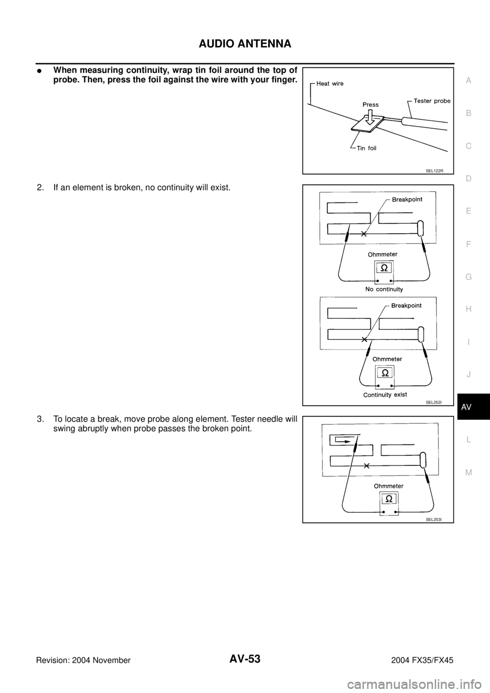
�When measuring continuity, wrap tin foil around the top of
probe. Then, press the foil against the wire with your finger.
2. If an element is broken, no continuity will exist.
3. To locate a break, move probe along element. Tester needle will
swing abruptly when probe passes the broken point.
SEL122R
SEL252I
SEL253I
Page 645 of 4449
AV-54
AUDIO ANTENNA
Revision: 2004 November 2004 FX35/FX45
Removal and Installation of Roof AntennaAKS005TZ
REMOVAL
1. Remove head lining. Refer to EI-42, "HEADLINING" .
2. Remove nut and remove rod and antenna base.
3. Remove instrument panel. Refer to IP-10, "
INSTRUMENT
PANEL ASSEMBLY" .
4. Disassembly antenna feeder (upper) and antenna feeder
(lower).
5. Disengaged the clips (7) to separate antenna feeder (upper)
from vehicle.
6. Pull off antenna feeder (lower) from audio unit.
7. Disengaged the clips (5) to separate antenna feeder (lower)
from vehicle.
INSTALLATION
Install in the reverse order of removal.
PKIA2463E
SKIA5821E
Page 646 of 4449

INTEGRATED DISPLAY SYSTEM
AV-55
C
D
E
F
G
H
I
J
L
MA
B
AV
Revision: 2004 November 2004 FX35/FX45
INTEGRATED DISPLAY SYSTEMPFP:28090
System DescriptionAKS00BO5
A/C AND AV SWITCH SYSTEM
Refer to Owner′s Manual for A/C and AV switch operating instructions.
Using the A/C and AV switch at the center of the instrument panel, the controls of the following systems are
centralized:
�Integrated display system (Drive computer, setting screen, etc.)
�Auto A/C system
�Audio system
PRECAUTION OF LCD MONITOR
�In order to use LED for backlight of a display, by in car temperature, brightness may change. In low tem-
perature, the refreshing rate of the picture also becomes low because of the low response of the LCD
monitor. When passenger room becomes warm, however, the LCD recovers the normal display.
�Backlight sometimes flickers or darkens according to the total consumption hours and the number of times
switched ON and OFF. In this case, display unit should be replaced. (Exchange only of backlight is impos-
sible.)
POWER SUPPLY AND GROUND
Power is supplied at all times
�through 15A fuse (No. 32, located in fuse and fusible link box)
�to display unit terminal 1, and
�to A/C and AV switch terminal 1.
When ignition switch is in ACC or ON position, power is supplied
�through 10A fuse [No. 6, located in fuse block (J/B)]
�to display unit terminal 2, and
�to A/C and AV switch terminal 2.
When ignition switch is in ON or START position, power is supplied
�through 10A fuse [No. 12, located in fuse block (J/B)]
�to display unit terminal 3.
Ground is supplied
�to display unit terminals 6 and 15, and
�to A/C and AV switch terminal 5
�through body grounds M35, M45 and M85.
Page 663 of 4449

ItemSignal
input/
outputCondition
VoltageExampl")
AV-72
INTEGRATED DISPLAY SYSTEM
Revision: 2004 November 2004 FX35/FX45
Terminals and Reference Value for Display UnitAKS00BOD
Terminal No.
(Wire color)
ItemSignal
input/
outputCondition
VoltageExample of
symptom
+–Ignition
switchOperation
1 (W/L) GroundBattery power
supplyInput OFF - Battery voltageSystem does not
work properly.
2 (LG/R) GroundACC power
supplyInput ACC - Battery voltageSystem does not
work properly.
3 (G/R) Ground Ignition signal Input ON - Battery voltageA/C operation is
not possible.
Vehicle informa-
tion setting is not
possible.
4 (R/L) GroundIllumination
signalInput OFFLighting switch is
ON .Approx. 12VScreen does not
switch to night-
time mode after
the lighting switch
is turned ON. Llighting switch is
OFF.Approx. 0V
6 (B) Ground Ground - ON - Approx. 0V -
7 (R/G) GroundVehicle speed
signal (8-pulse)Input ONWhen vehicle
speed is approx.
40 km/h (25 MPH)Drive computer
item is not dis-
played correctly.
8 (LG) Ground Audio TX Output ONOperate audio
volume.Audio does not
operate properly.
9 - Shield ground - - - - -
10 (B/Y) Ground Audio RX Input ONOperate audio
volume.Audio does not
operate properly.
11 (B/R) GroundCommunica-
tion signal (+)Input/
outputON -System does not
work properly.
12 - Shield ground - - - - -
PKIA1935E
SKIA4402E
SKIA4403E
SKIA0175E
Page 664 of 4449
 GroundCommunica-
tion signal (-)In")
INTEGRATED DISPLAY SYSTEM
AV-73
C
D
E
F
G
H
I
J
L
MA
B
AV
Revision: 2004 November 2004 FX35/FX45
Terminals and Reference Value for A/C and AV SwitchAKS00BOE
13 (W/R) GroundCommunica-
tion signal (-)Input/
outputON -System does not
work properly.
14 (L) - CAN-H - - - - -
15 (B) - Shield ground - - - - -
16 (R) - CAN-L - - - - -Terminal No.
(Wire color)
ItemSignal
input/
outputCondition
Voltag eExample of
symptom
+–Ignition
switchOperation
SKIA0176E
Terminal No.
(Wire color)
ItemSignal
input/
outputCondition
Vo l ta g eExample of
symptom
+–Ignition
switchOperation
1 (W/L) GroundBattery power
suoplyInput OFF - Battery voltageSystem does not
work properly.
2 (LG/R) GroundACC power
supply Input ACC - Battery voltageSystem does not
work properly.
5 (B) Ground Ground - ON - Approx. 0V -
6 (B/R) GroundCommunica-
tion signal (+)Input/
outputON -System does not
work properly.
7 - Shield ground - - - - -
8 (W/R) GroundCommunica-
tion signal (-)Input/
outputON -System does not
work properly.
12 (R/G) GroundRemote con-
troller AInput ONPress MODE
switch. Approx. 0V
Audio steering
wheel switches
do not function. Press SEEK UP
switch.Approx. 1.7V
Press VOL UP
switch.Approx. 3.3V
Except for above Approx. 5V
SKIA0175E
SKIA0176E

 to antenna terminal on
e")