Page 677 of 4449

AV-86
INTEGRATED DISPLAY SYSTEM
Revision: 2004 November 2004 FX35/FX45
2. CHECK HARNESS
1. Turn ignition switch OFF.
2. Disconnect A/C and AV switch connector and spiral cable connector (Vehicle harness side).
3. Check continuity between spiral cable harness connector termi-
nals and A/C and AV switch harness connector terminals.
4. Check continuity between A/C and AV switch harness connector
terminals and ground.
OK or NG
OK >> GO TO 3
NG >> Repair harness or connector.
3. CHECK SPIRAL CABLE
1. Disconnect spiral cable connector (Audio steering wheel switch harness side).
2. Check continuity between spiral cable connector terminals.
OK or NG
OK >> GO TO 4
NG >> Replace spiral cable.
Terminals
Continuity Spiral cable A/C and AV switch
ConnectorTerminal
(Wire color)ConnectorTerminal
(Wire color)
M1524 (R/G)
M6412 (R/G)
Ye s 31 (B/Y) 14 (B/Y)
32 (G/W) 13 (G/W)
Te r m i n a l s
Continuity A/C and AV switch
Ground Connector Terminal (wire color)
M6412 (R/G)
No 13 (G/W)
14 (B/Y)
SKIB0522E
Terminals
Continuity Spiral cable
ConnectorTerminal
(Wire color)Connector Terminal
M1524
M20320
Ye s 31 17
32 16
SKIB0521E
Page 678 of 4449

INTEGRATED DISPLAY SYSTEM
AV-87
C
D
E
F
G
H
I
J
L
MA
B
AV
Revision: 2004 November 2004 FX35/FX45
4. CHECK AUDIO STEERING WHEEL SWITCH
Check resistance audio steering wheel switch connector M203 ter-
minals.
OK or NG
OK >> Replace A/C and AV switch.
NG >> Replace audio steering wheel switch.
Removal and Installation of DisplayAKS00BOS
REMOVAL
1. Remove audio unit. Refer to AV- 4 4 , "Removal and Installation of
Audio Unit" .
2. Remove screws (4), and remove display.
INSTALLATION
Install in the reverse order of removal.
Removal and Installation of A/C and AV SwitchAKS00BOT
Refer toAV- 4 5 , "Removal and Installation for A/C and AV Switch" .
Terminal
(Wire color)Switch name ConditionResistance
(Ω)
16
(L)
17
(BR)Power Depress power switch. Approx. 0
Seek down Depress seek down switch. Approx. 165
Volume (down) Depress volume down switch. Approx. 652
20
(W)Mode Depress mode switch. Approx. 0
Seek up Depress seek up switch. Approx. 165
Volume (up) Depress volume up switch. Approx. 652
SKIA9400E
SKIA6167E
Page 714 of 4449

NAVIGATION SYSTEM
AV-123
C
D
E
F
G
H
I
J
L
MA
B
AV
Revision: 2004 November 2004 FX35/FX45
Terminals and Reference Value for Display Control UnitAKS00BMZ
Terminal
(Wire color)
ItemSignal
input/
outputCondition
Reference valueExample of
symptom
+–Igni-
tion
switchOperation
1 (W/L) GroundBattery
Power supplyInput OFF – Battery voltageSystem does not
work properly.
2 (W/G) GroundPower Sup-
ply (Inverter) Output ON – Approx. 9VScreen is not
shown
3 (B) Ground Ground – ON – Approx. 0V –
4 (BR/W) GroundPower Sup-
ply (Signal) Output ON – Approx. 9VScreen is not
shown
5 (P) Ground(Inverter)
Ground – ON – Approx. 0VScreen is not
shown
6 (OR) GroundReverse
signalInput ONSelector lever in R
positionApprox. 12V
Impossible to
gain direction of
vehicle. Selector lever
except R positionApprox. 0V
7 (P/L) Ground(Signal)
Ground – ON – Approx. 0V –
10 (LG/R) GroundACC power
supplyInput ACC – Battery voltageSystem does not
work properly.
12 (G/R) Ground Ignition signal Input ON – Battery voltageA/C operation is
not possible.
Vehicle informa-
tion setting is not
possible.
13 (B) Ground sysco – ON – Approx. 0V –
14 (R/L) GroundIllumination
signalInput OFFLighting switch is
ON.Approx. 12VAudio unit illumi-
nation does not
come on when
lighting switch is
ON. Lighting switch is
OFF.Approx. 0V
16 (R/G) GroundVehicle
speed signal
(8–pulse)Input ONWhen vehicle speed
is approx. 40 km/h
(25 MPH)Value of vehicle
information is
not accurately
displayed.
25 (L) – CAN H – – – – –
26 (R) – CAN L – – – – –
28 (B/R) GroundCommunica-
tion signal (+)Input/
OutputON –System does not
work properly.
29 –Shield
ground–– – – –
PKIA1935E
SKIA0175E
Page 715 of 4449

AV-124
NAVIGATION SYSTEM
Revision: 2004 November 2004 FX35/FX45
30 (W/R) GroundCommunica-
tion signal (–)Input/
outputON –System does not
work properly.
32 (BR) GroundCommunica-
tion signal (+)Input/
outputON –System does not
work properly.
33 –Shield
ground–– – – –
34 (Y) GroundCommunica-
tion signal (–)Input/
outputON –System does not
work properly.
36 (PU) GroundDisplay Com-
munication
signal
(DCU-DSP)Output ONPress the “TRIP”
button.Though a screen
is displayed, it is
impossible to
adjust bright-
ness.
37 –Shield
ground–– – – –
38 (LG) GroundDisplay Com-
munication
signal
(DSP-DCU)Input ONPress the “TRIP”
button.Though a screen
is displayed, it is
impossible to
adjust bright-
ness.
39 –Shield
ground–– – – –
40 (LG) GroundAudio RX
Communica-
tion signalInput ONOperate audio
volume.Audio dose not
operate properly. Terminal
(Wire color)
ItemSignal
input/
outputCondition
Reference valueExample of
symptom
+–Igni-
tion
switchOperation
SKIA0176E
SKIA0175E
SKIA0176E
SKIA4364E
SKIA4363E
SKIA4403E
Page 716 of 4449

NAVIGATION SYSTEM
AV-125
C
D
E
F
G
H
I
J
L
MA
B
AV
Revision: 2004 November 2004 FX35/FX45
41 –Shield
ground–– – – –
42 (B/Y) GroundAudio TX
communica-
tion signalOutput ONOperate audio
volume.Audio dose not
operate properly.
43 (G/B) 41RGB syn-
chronizing
signalInput ONPress the “MAP”
button.NAVI screen is
rolling.
44 (R/W) 45RGB signal
(R: red)Input ONSelect “Display
Diagnosis (NAVI)” of
CONFIRMATION/
ADJUSTMENT
function.NAVI screen
looks bluish.
45 –Shield
ground–– – – –
46 (R/L) 45RGB signal
(G: green)Input ONSelect “Display
Diagnosis (NAVI)” of
CONFIRMATION/
ADJUSTMENT
function.NAVI screen
looks reddish.
47 –Shield
ground–– – – –
48 (B) 45RGB signal
(B: blue)Input ONSelect “Display
Diagnosis (NAVI)” of
CONFIRMATION/
ADJUSTMENT
function.NAVI screen
looks yellowish.
49 –Shield
ground–– – – –
50 (L/R) 47RGB signal
(R: red)Output ONSelect “Display
Diagnosis (DCU)” of
CONFIRMATION/
ADJUSTMENT
function.RGB screen
looks bluish. Terminal
(Wire color)
ItemSignal
input/
outputCondition
Reference valueExample of
symptom
+–Igni-
tion
switchOperation
SKIA4402E
SKIA0164E
SKIA4977E
SKIA4978E
SKIA4979E
SKIA4980E
Page 717 of 4449
AV-126
NAVIGATION SYSTEM
Revision: 2004 November 2004 FX35/FX45
51 (B) 49RGB area
(YS) signalOutput ONPress the“TRIP”
button.RGB screen is
not shown.
52 (L/W) 47RGB signal
(G: green)Output ONSelect “Display
Diagnosis (DCU)” of
CONFIRMATION/
ADJUSTMENT
function.RGB screen
looks reddish.
53 (W) 49Vertical syn-
chronizing
(VP) signalInput ONSelector lever in
R position.Audio and A/C
does not operate
properly.
54 (L) 47RGB signal
(B: blue)Output ONSelect “Display
Diagnosis (DCU)” of
CONFIRMATION/
ADJUSTMENT
function.RGB screen
looks yellowish.
55 (R) 49Horizontal
synchroniz-
ing (HP) sig-
nalInput ON –Audio and A/C
does not operate
properly.
56 (G) 49RGB syn-
chronizing
signalOutput ONPress the “TRIP”
button.NAVI screen is
rolling. Terminal
(Wire color)
ItemSignal
input/
outputCondition
Reference valueExample of
symptom
+–Igni-
tion
switchOperation
SKIA0162E
SKIA4981E
SKIA0161E
SKIA4982E
SKIA4983E
SKIA0164E
Page 722 of 4449

NAVIGATION SYSTEM
AV-131
C
D
E
F
G
H
I
J
L
MA
B
AV
Revision: 2004 November 2004 FX35/FX45
Self-Diagnosis Mode (DCU)AKS00BN3
OPERATION PROCEDURE
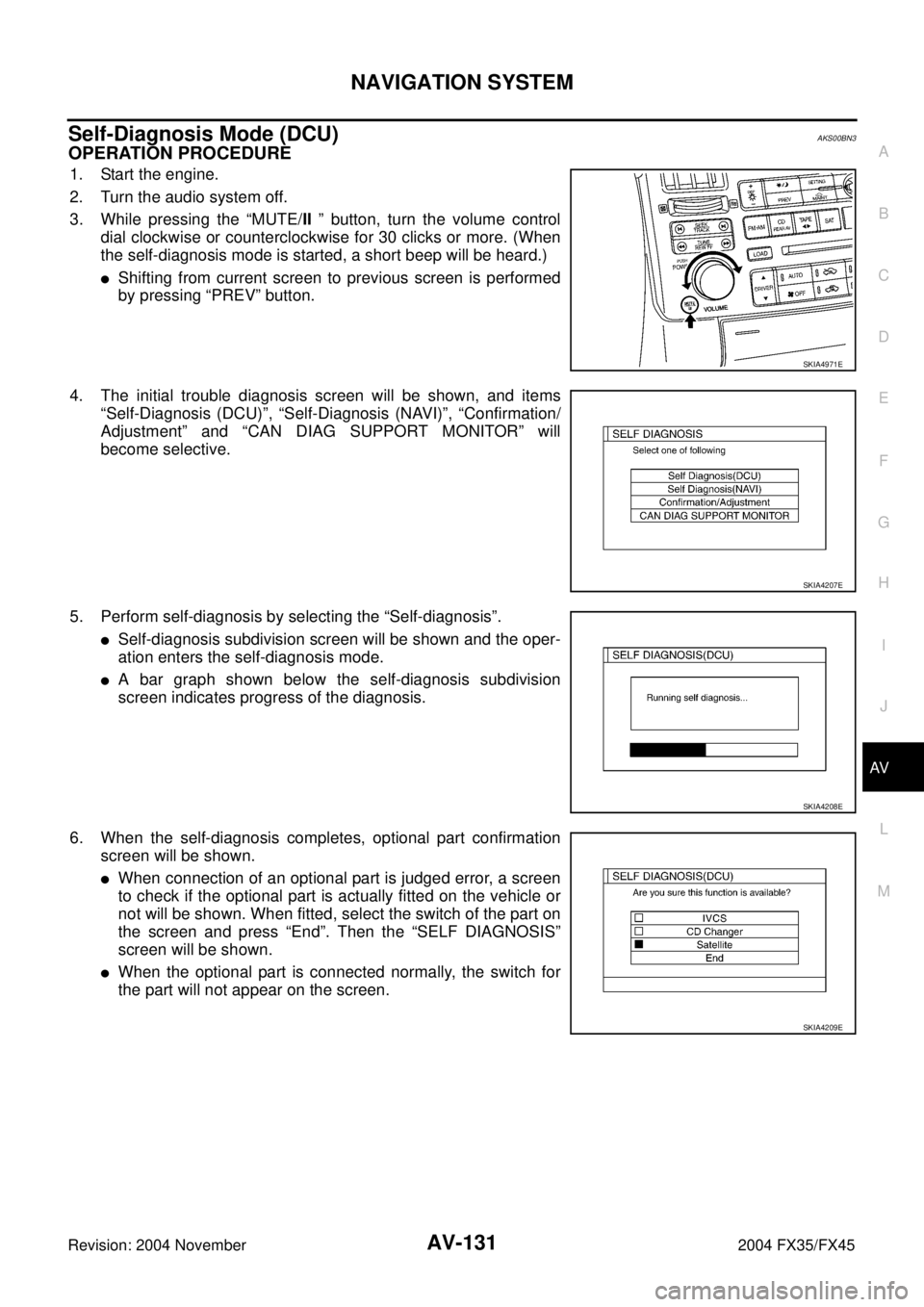
1. Start the engine.
2. Turn the audio system off.
3. While pressing the “MUTE/II ” button, turn the volume control
dial clockwise or counterclockwise for 30 clicks or more. (When
the self-diagnosis mode is started, a short beep will be heard.)
�Shifting from current screen to previous screen is performed
by pressing “PREV” button.
4. The initial trouble diagnosis screen will be shown, and items
“Self-Diagnosis (DCU)”, “Self-Diagnosis (NAVI)”, “Confirmation/
Adjustment” and “CAN DIAG SUPPORT MONITOR” will
become selective.
5. Perform self-diagnosis by selecting the “Self-diagnosis”.
�Self-diagnosis subdivision screen will be shown and the oper-
ation enters the self-diagnosis mode.
�A bar graph shown below the self-diagnosis subdivision
screen indicates progress of the diagnosis.
6. When the self-diagnosis completes, optional part confirmation
screen will be shown.
�When connection of an optional part is judged error, a screen
to check if the optional part is actually fitted on the vehicle or
not will be shown. When fitted, select the switch of the part on
the screen and press “End”. Then the “SELF DIAGNOSIS”
screen will be shown.
�When the optional part is connected normally, the switch for
the part will not appear on the screen.
SKIA4971E
SKIA4207E
SKIA4208E
SKIA4209E
Page 724 of 4449

NAVIGATION SYSTEM
AV-133
C
D
E
F
G
H
I
J
L
MA
B
AV
Revision: 2004 November 2004 FX35/FX45
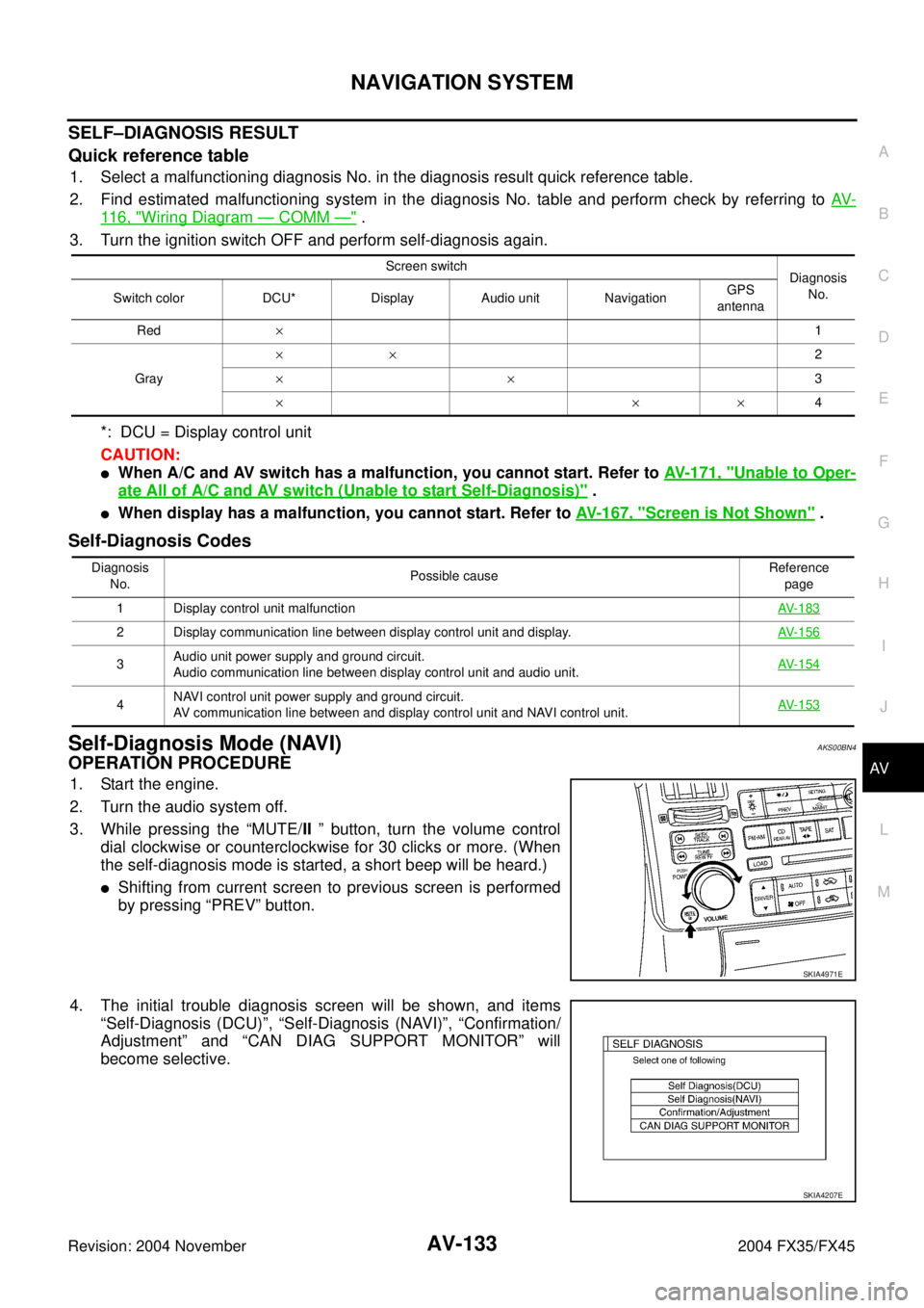
SELF–DIAGNOSIS RESULT
Quick reference table
1. Select a malfunctioning diagnosis No. in the diagnosis result quick reference table.
2. Find estimated malfunctioning system in the diagnosis No. table and perform check by referring to AV-
11 6 , "Wiring Diagram — COMM —" .
3. Turn the ignition switch OFF and perform self-diagnosis again.
*: DCU = Display control unit
CAUTION:
�When A/C and AV switch has a malfunction, you cannot start. Refer to AV- 1 7 1 , "Unable to Oper-
ate All of A/C and AV switch (Unable to start Self-Diagnosis)" .
�When display has a malfunction, you cannot start. Refer to AV- 1 6 7 , "Screen is Not Shown" .
Self-Diagnosis Codes
Self-Diagnosis Mode (NAVI)AKS00BN4
OPERATION PROCEDURE
1. Start the engine.
2. Turn the audio system off.
3. While pressing the “MUTE/II ” button, turn the volume control
dial clockwise or counterclockwise for 30 clicks or more. (When
the self-diagnosis mode is started, a short beep will be heard.)
�Shifting from current screen to previous screen is performed
by pressing “PREV” button.
4. The initial trouble diagnosis screen will be shown, and items
“Self-Diagnosis (DCU)”, “Self-Diagnosis (NAVI)”, “Confirmation/
Adjustment” and “CAN DIAG SUPPORT MONITOR” will
become selective.
Screen switch
Diagnosis
No.
Switch color DCU* Display Audio unit NavigationGPS
antenna
Red×1
Gray××2
××3
×××4
Diagnosis
No.Possible causeReference
page
1 Display control unit malfunctionAV-183
2 Display communication line between display control unit and display. AV-156
3Audio unit power supply and ground circuit.
Audio communication line between display control unit and audio unit.AV-154
4NAVI control unit power supply and ground circuit.
AV communication line between and display control unit and NAVI control unit.AV-153
SKIA4971E
SKIA4207E