Page 665 of 4449

AV-74
INTEGRATED DISPLAY SYSTEM
Revision: 2004 November 2004 FX35/FX45
On Board Self-Diagnosis FunctionAKS00BOF
DESCRIPTION
�Diagnosis function consists of the self-diagnosis mode performed automatically.
�Self-diagnosis mode checks for connections between the units constituting this system, analyzes each
individual unit at the same time, and displays the results on the LCD screen.
DIAGNOSIS ITEM
Self-Diagnosis ModeAKS00BOG
OPERATION PROCEDURES
1. Start the engine.
2. Turn the audio system off.
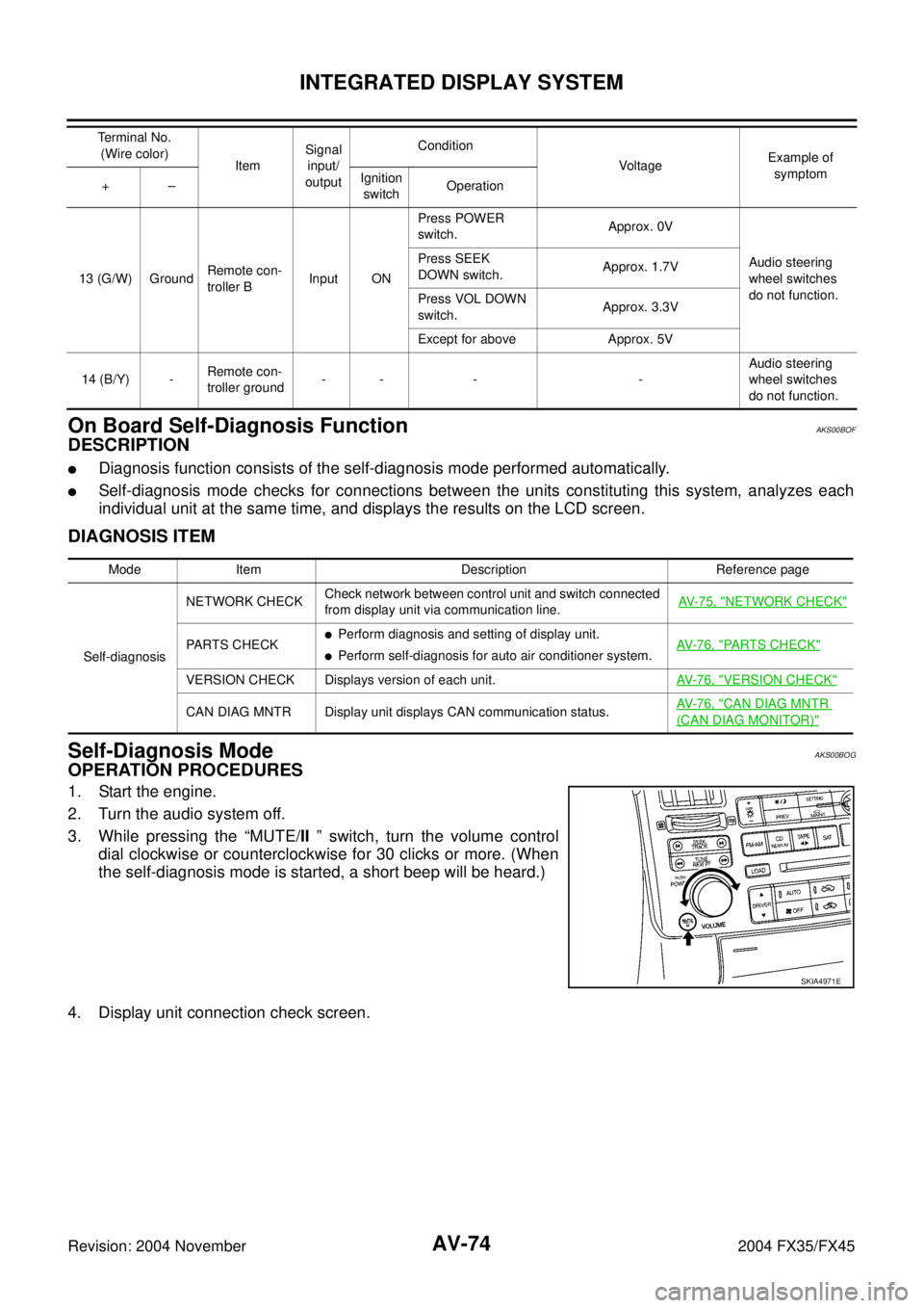
3. While pressing the “MUTE/II ” switch, turn the volume control
dial clockwise or counterclockwise for 30 clicks or more. (When
the self-diagnosis mode is started, a short beep will be heard.)
4. Display unit connection check screen.
13 (G/W) GroundRemote con-
troller BInput ONPress POWER
switch.Approx. 0V
Audio steering
wheel switches
do not function. Press SEEK
DOWN switch.Approx. 1.7V
Press VOL DOWN
switch.Approx. 3.3V
Except for above Approx. 5V
14 (B/Y) -Remote con-
troller ground-- - -Audio steering
wheel switches
do not function. Terminal No.
(Wire color)
ItemSignal
input/
outputCondition
VoltageExample of
symptom
+–Ignition
switchOperation
Mode Item Description Reference page
Self-diagnosisNETWORK CHECKCheck network between control unit and switch connected
from display unit via communication line.AV-75, "
NETWORK CHECK"
PARTS CHECK�Perform diagnosis and setting of display unit.
�Perform self-diagnosis for auto air conditioner system.AV- 7 6 , "PARTS CHECK"
VERSION CHECK Displays version of each unit.AV- 7 6 , "VERSION CHECK"
CAN DIAG MNTR Display unit displays CAN communication status.AV- 7 6 , "CAN DIAG MNTR
(CAN DIAG MONITOR)"
SKIA4971E
Page 666 of 4449
INTEGRATED DISPLAY SYSTEM
AV-75
C
D
E
F
G
H
I
J
L
MA
B
AV
Revision: 2004 November 2004 FX35/FX45
5. Select each connecting unit (CHANGER, SATELLITE RADIO).
6. Self-diagnosis screen is displayed.
�Using the joystick, select each item, and perform diagnosis.
CAUTION:
If self-diagnosis cannot activated, refer to AV- 7 8 , "
Trouble
Diagnosis Chart by Symptom" .
NETWORK CHECK
Selecting NETWORK CHECK on self-diagnosis screen, display self-
diagnostic results.
SKIA5921E
SKIA5922E
SKIA5923E
Diagnosis item Contents DTC return condition Reference at error
HVAC OK/NGCommunication error between unified meter and A/C amp. and dis-
play unit.AV-85, "
CAN Communica-
tion Line Inspection"
SWITCH OK/NG Communication error between A/C and AV switch and display unit.AV-84, "A/C and AV Switch
Does Not Operate"
AUDIO OK/NG Communication error between audio and display unit.AV-82, "Audio Communica-
tion Line Inspection"
Page 667 of 4449

AV-76
INTEGRATED DISPLAY SYSTEM
Revision: 2004 November 2004 FX35/FX45
PARTS CHECK
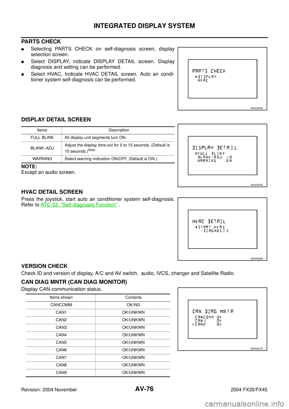
�Selecting PARTS CHECK on self-diagnosis screen, display
selection screen.
�Select DISPLAY, indicate DISPLAY DETAIL screen. Display
diagnosis and setting can be performed.
�Select HVAC, Indicate HVAC DETAIL screen. Auto air condi-
tioner system self-diagnosis can be performed.
DISPLAY DETAIL SCREEN
NOTE:
Except an audio screen.
HVAC DETAIL SCREEN
Press the joystick, start auto air conditioner system self-diagnosis.
Refer to AT C - 5 3 , "
Self-diagnosis Function" .
VERSION CHECK
Check ID and version of display, A/C and AV switch, audio, IVCS, changer and Satellite Radio.
CAN DIAG MNTR (CAN DIAG MONITOR)
Display CAN communication status.
SKIA5924E
Items Description
FULL BLINK All display unit segments turn ON.
BLANK–ADJAdjust the display time-out for 5 to 15 seconds. (Default is
10 seconds.)
Note
WARNING Select warning indication ON/OFF. (Default is ON.)
SKIA5925E
SKIA5926E
Items shown Contents
CANCOMM OK/NG
CAN1 OK/UNKWN
CAN2 OK/UNKWN
CAN3 OK/UNKWN
CAN4 OK/UNKWN
CAN5 OK/UNKWN
CAN6 OK/UNKWN
CAN7 OK/UNKWN
CAN8 OK/UNKWN
CAN9 OK/UNKWN
SKIA5927E
Page 668 of 4449
INTEGRATED DISPLAY SYSTEM
AV-77
C
D
E
F
G
H
I
J
L
MA
B
AV
Revision: 2004 November 2004 FX35/FX45
A/C and AV Switch Self-Diagnosis FunctionAKS00BOH
It can check ON/OFF operation of each switch in the A/C and AV switch and diagnose the input signals to the
steering switch (audio).
STARTING THE SELF-DIAGNOSIS MODE
1. Turn ignition switch from OFF to ACC.
2. Within 10 seconds press and hold the switches “MUTE/II ” and
“PREV ” simultaneously for 3 seconds.
DIAGNOSIS FUNCTION
The following are checked:
�All the indicators (LED) in the A/C and AV switch.
�Continuity of the switches by sounding the buzzer when the A/C and AV switch is pressed.
�Continuity of harness between A/C and AV switch and steering switch (audio).
EXITING THE SELF-DIAGNOSIS MODE
�Turn ignition switch OFF. Then the self-diagnosis ends.
SKIA4972E
Page 673 of 4449

AV-82
INTEGRATED DISPLAY SYSTEM
Revision: 2004 November 2004 FX35/FX45
Ignition Signal InspectionAKS00BON
1. CHECK IGNITION SIGNAL
1. Disconnect display unit connector.
2. Turn ignition switch ON.
3. Check voltage between display unit harness connector M62 ter-
minal 3 (G/R) and ground.
OK or NG
OK >> INSPECTION END
NG >> Repair harness or connector.
Audio Communication Line InspectionAKS00BOO
1. CHECK HARNESS
1. Turn ignition switch OFF.
2. Disconnect audio unit connector and display unit connector.
3. Check continuity between audio unit harness connector termi-
nals and display unit harness connector terminals.
4. Check continuity between display unit harness connector termi-
nals and ground.
OK or NG
OK >> GO TO 2.
NG >> Repair harness or connector.3 – Ground : Battery voltage
SKIB0447E
Terminals
Continuity Display unit Audio unit
ConnectorTerminal
(Wire color)ConnectorTerminal
(Wire color)
M628 (LG)
M6023 (LG)
Ye s 10 (B/Y) 21 (B/Y)
925
SKIA9935E
Terminals
Continuity Display unit
Ground Connector Terminal (Wire color)
M628 (LG)
No
10 (B/Y)
SKIA9936E
Page 674 of 4449

INTEGRATED DISPLAY SYSTEM
AV-83
C
D
E
F
G
H
I
J
L
MA
B
AV
Revision: 2004 November 2004 FX35/FX45
2. CHECK AUDIO UNIT
1. Connect audio unit connector.
2. Turn ignition switch ON.
3. Check voltage between audio unit harness connector M60 ter-
minal 23 (LG) and ground.
OK or NG
OK >> GO TO 3.
NG >> Replace audio unit.
3. CHECK DISPLAY UNIT
1. Turn ignition switch OFF.
2. Dsconnect audio unit connector, and connect display unit connector.
3. Turn ignition switch ON.
4. Check voltage between display unit harness connector M62 ter-
minal 10 (B/Y) and ground.
OK or NG
OK >> GO TO 4.
NG >> Replace display unit.
4. CHECK AUDIO TX COMMUNICATION SIGNAL
1. Turn ignition switch OFF.
2. Connect audio unit connector.
3. Turn ignition switch ON.
4. Check signal between display unit harness connector M62 ter-
minal 8 (LG) and ground with CONSULT-ll or oscilloscope.
OK or NG
OK >> GO TO 5.
NG >> Replace dispaly unit.23 – Ground : Approx. 4V
SKIA9484E
10 – Ground : Approx. 4V
SKIA9485E
8 – Ground:
SKIA4995E
SKIA4402E
Page 675 of 4449

AV-84
INTEGRATED DISPLAY SYSTEM
Revision: 2004 November 2004 FX35/FX45
5. CHECK AUDIO RX COMMUNICATION SIGNAL
1. Turn ignition switch ON.
2. Check signal between display unit harness connector M62 ter-
minal 10 (B/Y) and ground with CONSULT-ll or oscilloscope.
OK or NG
OK >> INSPECTION END
NG >> Replace audio unit.
A/C and AV Switch Does Not OperateAKS00BOP
1. CHECK A/C AND AV SWITCH
Check A/C and AV switch. Refer to AV- 4 1 , "
A/C and AV Switch Inspection" .
OK or NG
OK >> GO TO 2.
NG >> Repair malfunctioning parts.
2. CHECK A/C AND AV SWITCH CIRCUIT
1. Turn ignition switch OFF.
2. Disconnect display unit connector and A/C and AV switch connector.
3. Check continuity between display unit and A/C and AV switch.
4. Check continuity between display unit and ground.
OK or NG
OK >> GO TO 3.
NG >> Repair harness or connector.10 – Ground:
SKIA4999E
SKIA4403E
Terminals
Continuity Display unit A/C and AV switch
ConnectorTerminal
(Wire color)ConnectorTe r m i n a l
(Wire color)
M6211 (B/R)
M646 (B/R)
Ye s 13 (W/R) 8 (W/R)
12 7
SKIB0523E
Terminals
Continuity Display unit
Ground Connector Terminals
M6211 ( B / R )
No
13 (W/R)
SKIA7146E
Page 676 of 4449

INTEGRATED DISPLAY SYSTEM
AV-85
C
D
E
F
G
H
I
J
L
MA
B
AV
Revision: 2004 November 2004 FX35/FX45
3. CHECK AV COMMUNICATION SIGNAL
1. Replace A/C and AV switch.
2. Check A/C and AV switch if it functions normally.
OK or NG
OK >> INSPECTION END
NG >> Replace display unit switch.
CAN Communication Line InspectionAKS00BOQ
1. CHECK MONITOR DESCRIPTION
1. Start display unit self-diagnosis. Refer to AV- 7 4 , "
Self-Diagnosis Mode" .
2. Select “CAN DIAG MNTR”. Refer to AV- 7 6 , "
CAN DIAG MNTR
(CAN DIAG MONITOR)" .
3. Record each item display description (OK/NG/UKNWN) displayed on the following CAN DIAG MONITOR
Check Sheet.
CAN DIAG MONITOR Check Sheet
>> After filling in CAN DIAG MONITOR Check Sheet, go to LAN-4, "
Precautions When Using CON-
SULT-II" .
Audio Steering Wheel Switch InspectionAKS00BOR
1. A/C AND AV SWITCH SELF-DIAGNOSIS FUNCTION
1. Start A/C and AV switch self-diagnosis function. Refer to AV- 3 5 , "
A/C and AV Switch Self-Diagnosis Func-
tion" .
2. Operate audio steering wheel switch.
Does the audio steering wheel switch is operated normally?
YES >> INSPECTION END (System is OK)
NO >> GO TO 2
Diagnosis itemData monitor display description
Normal conditionAbnormal condition
(example)
CANCOMM OK NG
CAN1 OK UNKWN
CAN2 OK UNKWN
CAN3 OK UNKWN
CAN4 OK UNKWN
CAN5 OK UNKWN
CAN6 OK UNKWN
CAN7 OK UNKWN
CAN8 OK UNKWN
CAN9 OK UNKWN
SKIA5927E
Diagnosis item Screen display Diagnosis item Screen display
CANCOMM OK NG CAN5 OK UNKWN
CAN1 OK UNKWN CAN6 OK UNKWN
CAN2 OK UNKWN CAN7 OK UNKWN
CAN3 OK UNKWN CAN8 OK UNKWN
CAN4 OK UNKWN CAN9 OK UNKWN