2004 INFINITI FX35 child seat
[x] Cancel search: child seatPage 3278 of 4449
IDX-5
A
C
D
E
F
G
H
I
J
K
L B
IDX
ALPHABETICAL INDEX
LT-73
Headlining - See Roof trim .................................. EI-42
Heated oxygen sensor 1 (bank 1) .... EC-205, EC-214,
EC-226
, EC-433, EC-439, EC-863, EC-872, EC-884,
EC-1103
, EC-1109
Heated oxygen sensor 1 (bank 2) .... EC-205, EC-214,
EC-226
, EC-433, EC-439, EC-863, EC-872, EC-884,
EC-1103
, EC-1109
Heated oxygen sensor 1 heater (bank 1) ....... EC-149,
EC-806
Heated oxygen sensor 1 heater (bank 2) ....... EC-149,
EC-806
Heated oxygen sensor 2 (bank 1) .... EC-236, EC-245,
EC-446
, EC-457, EC-894, EC-903, EC-1116, EC-1127
Heated oxygen sensor 2 (bank 2) .... EC-236, EC-245,
EC-446
, EC-457, EC-894, EC-903, EC-1116, EC-1127
Heated oxygen sensor 2 heater (bank 1) ....... EC-157,
EC-814
Heated oxygen sensor 2 heater (bank 2) ....... EC-157,
EC-814
Heated seat ....................................................... SE-98
Heater and cooling unit (Heater core) ........... ATC-126
HFC134a (R134a) system precaution ............... ATC-5
HFC134a (R134a) system service procedure ATC-137
HFC134a (R134a) system service tools .......... ATC-18
HFC134a system service equipment precaution ..........
ATC-13
High & low reverse clutch solenoid valve ....... AT-164,
AT-166
Hood ................................................................... BL-14
Horn ................................................................. WW-56
HORN - Wiring diagram ................................... WW-56
HSEAT - Wiring diagram ................................... SE-99
I
IATS - Wiring diagram ....................... EC-182
, EC-839
ICC - Wiring diagram ....................................... ACS-20
ICC/BS - Wiring diagram ................. EC-524, EC-1191
ICC/SW - Wiring diagram ................ EC-510, EC-1176
ICCBOF - Wiring diagram ................ EC-616, EC-1294
Idle air volume learning ....................... EC-49, EC-698
Idle mixture ratio .................................. EC-38, EC-687
Idle speed ............................................ EC-38, EC-687
Idle speed control (ISC) .... EC-392, EC-394, EC-1048,
EC-1050
Ignition coil ....................................... EC-585, EC-1262
Ignition coil(VK45DE) ...................................... EM-185
Ignition coil(VQ35DE) ........................................ EM-42
Ignition control system ..................... EC-585, EC-1262
Ignition key hole illumination ............................. LT-153
Ignition timing ...................................... EC-38, EC-687
IGNSYS - Wiring diagram ................ EC-586, EC-1263
Illumination control ............................................ LT-197
In vehicle sensor ........................... ATC-107, ATC-118
INF/D - Wring diagram ....................................... AV-63
INJECT - Wiring diagram ................. EC-598, EC-1275
Injector ............................................. EC-597, EC-1274
Input clutch solenoid valve ................. AT-152, AT-154
Instrument panel ................................................. IP-10
Intake air temperature sensor ........... EC-180, EC-200,
EC-837
, EC-858
Intake door control linkage adjustment ............ ATC-78
Intake door motor ............................ ATC-76, ATC-124
Intake manifold(VK45DE) ............................... EM-174
Intake manifold(VQ35DE) ................................. EM-24
Intake sensor ................................ ATC-113, ATC-120
Intake valve timing control (Bank 1) ... EC-145, EC-795
Intake valve timing control (Bank 2) ... EC-145, EC-795
Intake valve timing control position sensor (Bank 1) ....
EC-1095
Intake valve timing control position sensor (Bank 2) ....
EC-1095
Intake valve timing control solenoid valve (Bank 1) ......
EC-408
, EC-1070
Intake valve timing control solenoid valve (Bank 2) ......
EC-408
, EC-1070
Integrated homelink transmitter ....................... BL-228
Intelligent cruise control (ICC) system .............. ACS-6
Interior ................................................................. EI-37
Interior lamp ...................................................... LT-157
IPDM (Intelligent power distribution module engine
room) ................................................................. PG-18
IVCB1 - Wiring diagram .... EC-409, EC-798, EC-1071
IVCB2 - Wiring diagram .... EC-411, EC-800, EC-1073
IVCSB1 - Wiring diagram ............................... EC-1096
IVCSB2 - Wiring diagram ............................... EC-1098
IVIS (Infiniti vehicle immobilizer system) precautions ...
GI-3
J
Joint connector (J/C) .......................................... PG-76
K
Knock sensor (KS) ............................. EC-297
, EC-955
KS - Wiring diagram ........................... EC-298, EC-956
L
LAN system circuit ........................................... ATC-66
Laser beam aiming adjustment ....................... ACS-12
Latch (lower anchors and tether for children) system ...
SB-11
Line pressure solenoid valve ........................... AT-127
Line pressure test (A/T) ..................................... AT-52
Liquid gasket application ................................... LU-21
Liquid gasket application(VQ35DE) EM-6, LU-3, CO-3
Location of electrical units ................................. PG-70
Low coast brake solenoid valve ......... AT-168, AT-170
Low tire pressure warning system ...................... WT-7
Lubricant (R134a) A/C ........................ ATC-7, ATC-27
Lubrication circuit (engine)(VK45DE) ................ LU-23
Lubrication circuit (engine)(VQ35DE) .................. LU-5
Lubrication oil A/C .......................................... ATC-161
Page 3280 of 4449
IDX-7
A
C
D
E
F
G
H
I
J
K
L B
IDX
ALPHABETICAL INDEX
Propeller shaft ..................................................... PR-6
Propeller shaft on vehicle service ........................ PR-6
Propeller shaft vibration ....................................... PR-6
PS/SEN - Wiring diagram ................ EC-397, EC-1053
R
R/VIEW - Wiring diagram ................................... DI-84
Radiator(VK45DE) ............................................. CO-39
Radiator(VQ35DE) ............................................ CO-14
Rear axle ........................................................... RAX-5
Rear bumper ........................................................ EI-18
Rear combination lamp removal and installation ..........
LT-147
Rear door ............................................ BL-148, GW-80
Rear seat ......................................................... SE-107
Rear suspension ............................................... RSU-5
Rear view monitor ............................................... DI-81
Rear washer .................................................... WW-35
Rear window defogger ...................................... GW-86
Rear wiper ....................................................... WW-35
Refrigerant connection precaution ..................... ATC-8
Refrigerant discharging evacuating charging ATC-137
Refrigerant general precaution .......................... ATC-7
Refrigerant lines ............................................ ATC-137
Refrigerant pressure sensor ........... EC-609, EC-1287,
ATC-90
, ATC-155
Refrigeration cycle ........................................... ATC-21
Removal and installation (A/T) ........... AT-266, AT-269
Removal and installation (Transfer) .................... TF-43
Revolution sensor (A/T) ...................... AT-116, AT-260
Ring gear diff. inspection ................................. RFD-13
Rocker cover(VK45DE) ................................... EM-193
Rocker cover(VQ35DE) ..................................... EM-51
Room lamp - See Interior lamp ......................... LT-157
ROOM/L - Wiring diagram ................................ LT-164
RP/SEN - Wiring diagram ................ EC-610, EC-1288
S
Seal - See Exterior .............................................. EI-28
SEAT - Wiring diagram ...................................... SE-95
Seat belt inspection ............................................. SB-8
Seat belt pre-tensioner disposal ...................... SRS-49
Seat belt, front ..................................................... SB-4
Seat, rear ......................................................... SE-107
Self-diagnosis (Transfer) .................................... TF-21
SEN/PW - Wiring diagram ............... EC-490, EC-1157
SHIFT - Wiring diagram ................................... AT-236
Shift change signal ........................................ EC-1218
Shift lock system .............................................. AT-235
Shift schedule .................................................. AT-348
Shock absorber (rear) ....................................... RSU-9
Side air bag (satellite) sensor .......................... SRS-46
Side bearing preload diff. ................................. RFD-20
Side curtain air bag .......................................... SRS-43
Side flange installation diff. .............................. RFD-10
Side trim .............................................................. EI-37
SMJ (super multiple junction) ............................ PG-79
Spark plug replacement .................................... MA-26
Spark plug replacement(VQ35DE) ................... MA-19
Spark plug(VK45DE) ...................................... EM-186
Spark plug(VQ35DE) ........................................ EM-43
Specification value ............................. EC-131, EC-780
Speedometer ........................................................ DI-4
Spiral cable ..................................................... SRS-38
Spot lamp .......................................................... LT-184
SROOF - Wiring diagram ..................... BL-167, RF-14
SRS - See Supplemental Restraint System ..... SRS-5
SRS Trouble diagnoses .................................... SRS-7
Stabilizer bar (rear) ......................................... RSU-16
Stall test (A/T) .................................................... AT-51
Standardized relay ............................................. PG-81
START - Wiring diagram .................................... SC-11
Starter ................................................................ SC-10
Starting system .................................................. SC-10
Steering gear and linkage inspection ................ MA-35
Steering linkage ................................................. PS-19
Steering wheel and column ................... PS-10, PS-12
Steering wheel turning force .............................. PS-10
Step lamp .......................................................... LT-124
Stop lamp .......................................................... LT-116
Stop lamp switch .............................. EC-550, EC-1220
STOP/L - Wiring diagram .................................. LT-118
Sun roof, electric ................................................ RF-10
Sunload sensor ............................. ATC-110, ATC-119
Sunroof .................................................. RF-10, RF-25
Supplemental Restraint System ....................... SRS-5
Suspension ....................................................... MA-36
Symbols and abbreviations ...................... GI-10, GI-23
T
Tachometer ........................................................... DI-4
TCM circuit diagram ........................................... AT-50
TCM inspection table ......................................... AT-90
Thermostat(VK45DE) ....................................... CO-51
Thermostat(VQ35DE) ....................................... CO-26
Three way catalyst function (Bank 1) . EC-316, EC-971
Three way catalyst function (Bank 2) . EC-316, EC-971
Three way catalyst precautions ............................ GI-6
Three way catalyst(VK45DE) .......................... EM-178
Three way catalyst(VQ35DE) ........................... EM-26
Throttle control motor ....................... EC-428, EC-1090
Throttle control motor relay .............. EC-423, EC-1085
Throttle position sensor (TPS) .......... EC-190, EC-284,
EC-485
, EC-487, EC-569, EC-848, EC-942, EC-1152,
EC-1154
, EC-1239
Tie-rod ............................................................... PS-19
Timing chain(VK45DE) ................................... EM-196
Timing chain(VQ35DE) ..................................... EM-63
Tire rotation ............................................. WT-6, MA-34
Tooth contact diff. ........................................... RFD-24
Top tether strap child restraint ........................... SB-12
Torque converter installation AT-267, AT-268, AT-272
Torque convertor clutch solenoid valve AT-123, AT-125
TPS1 - Wiring diagram ...................... EC-286, EC-944
TPS2 - Wiring diagram ...................... EC-192, EC-850
Page 4078 of 4449
SB-1
SEAT BELTS
H RESTRAINTS
CONTENTS
C
D
E
F
G
I
J
K
L
M
SECTION SB
A
B
SB
Revision: 2004 November 2004 FX35/FX45
SEAT BELTS
PRECAUTIONS .......................................................... 2
Precautions for Supplemental Restraint System
(SRS) “AIR BAG” and “SEAT BELT PRE-TEN-
SIONER” .................................................................. 2
Precaution for Seat Belt Service .............................. 2
AFTER A COLLISION ........................................... 2
SEAT BELTS .............................................................. 4
System Description .................................................. 4
SEAT BELT WARNING CHIME ............................ 4
SEAT BELT WARNING LAMP .............................. 4
Removal and Installation of Front Seat Belt ............. 4
REMOVAL OF FRONT SEAT BELT RETRAC-
TOR ....................................................................... 5
INSTALLATION OF FRONT SEAT BELT
RETRACTOR ........................................................ 5
REMOVAL OF FRONT SEAT BELT BUCKLE ...... 5
INSTALLATION OF FRONT SEAT BELT
BUCKLE ................................................................ 5
Removal and Installation of Rear Seat Belt ............. 6REMOVAL OF REAR SEAT BELT RETRACTOR ..... 7
INSTALLATION OF REAR SEAT BELT RETRAC-
TOR ....................................................................... 7
Seat Belt Inspection .................................................. 8
AFTER A COLLISION ........................................... 8
PRELIMINARY CHECK ......................................... 8
SEAT BELT RETRACTOR ON-VEHICLE
INSPECTION ........................................................ 9
SEAT BELT RETRACTOR OFF-VEHICLE
INSPECTION ...................................................... 10
LATCH (LOWER ANCHORS AND TETHER FOR
CHILDREN) SYSTEM ............................................... 11
Removal and Installation ........................................ 11
REMOVAL ........................................................... 11
INSTALLATION ................................................... 11
TOP TETHER STRAP CHILD RESTRAINT ............. 12
Removal and Installation ........................................ 12
REMOVAL ........................................................... 12
INSTALLATION ................................................... 12
Page 4086 of 4449
SEAT BELTS
SB-9
C
D
E
F
G
I
J
K
L
MA
B
SB
Revision: 2004 November 2004 FX35/FX45
SEAT BELT RETRACTOR ON-VEHICLE INSPECTION
Emergency Locking Retractors (ELR) and Automatic Locking Retractors (ALR)
NOTE:
All seat belt retractors are of the Emergency Locking Retractors (ELR) type. In an emergency (sudden stop)
the retractor will lock and prevent the webbing from extending any further. All 3-point type seat belt retractors
except the driver's seat belt also have an Automatic Locking Retractors (ALR) mode. The ALR mode (also
called child restraint mode) is used when installing child seats. The ALR mode is activated when the seat belt
is fully extended. When the webbing is then retracted partially, the ALR mode automatically locks the seat belt
in a specific position so the webbing cannot be extended any further. To cancel the ALR mode, allow the seat
belt to fully wind back into the retractor.
Check the seat belt retractors using the following test(s) to determine if a retractor assembly is operating prop-
erly.
Stationary Inspection for ELR Function
Grasp the shoulder webbing and pull forward quickly. The retractor should lock and prevent the belt from
extending further.
Stationary Inspection for ALR Function
1. Pull out entire length of seat belt from retractor until a click is heard.
2. Retract the webbing partially. A clicking noise should be heard as the webbing retracts indicating that the
retractor is in the Automatic Locking Retractor (ALR) mode.
3. Grasp the seat belt and try to pull out the retractor. The webbing must lock and not extend any further. If
necessary replace the retractor assembly.
4. Allow the entire length of the webbing to retract to cancel the automatic locking mode.
Moving Inspection for ELR Function
WARNING:
Perform the following test in a safe, open area clear of other vehicles and obstructions (for example, a
large, empty parking lot). Road surface must be paved and dry. DO NOT perform the following test on
wet or gravel roads or on public streets and highways. This could result in an accident and serious
personal injury. The driver and passenger must be prepared to brace themselves in the event the
retractor does not lock.
1. Fasten driver's seat belt. Buckle a passenger into the seat for the belt that is to be tested.
2. Proceed to the designated safe area.
3. Drive the vehicle at approximately 16 km/h (10 MPH). Notify any passengers of a pending sudden stop.
The driver and passenger must be prepared to brace themselves in the event the retractor does not lock.
Apply brakes firmly and make a very hard stop.
During stop, seat belts should lock and not be extended. If the seat belt retractor assembly does not lock, per-
form the retractor off-vehicle inspection.
Page 4088 of 4449
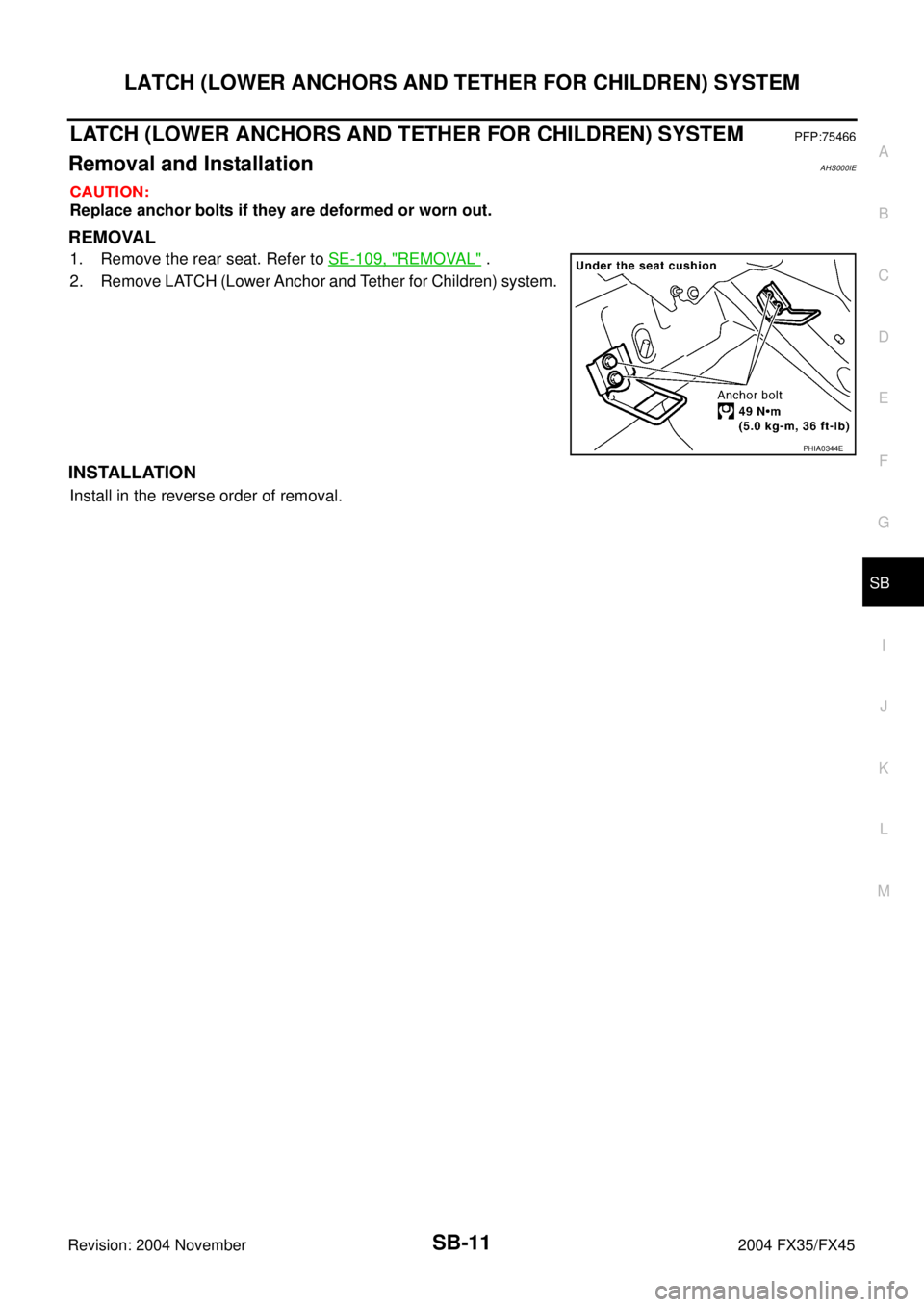
LATCH (LOWER ANCHORS AND TETHER FOR CHILDREN) SYSTEM
SB-11
C
D
E
F
G
I
J
K
L
MA
B
SB
Revision: 2004 November 2004 FX35/FX45
LATCH (LOWER ANCHORS AND TETHER FOR CHILDREN) SYSTEMPFP:75466
Removal and InstallationAHS000IE
CAUTION:
Replace anchor bolts if they are deformed or worn out.
REMOVAL
1. Remove the rear seat. Refer to SE-109, "REMOVAL" .
2. Remove LATCH (Lower Anchor and Tether for Children) system.
INSTALLATION
Install in the reverse order of removal.
PHIA0344E