Page 647 of 4449

AV-56
INTEGRATED DISPLAY SYSTEM
Revision: 2004 November 2004 FX35/FX45
DRIVE COMPUTER
Refer to Owner′s Manual for drive computer operating instructions.
TRIP Switch
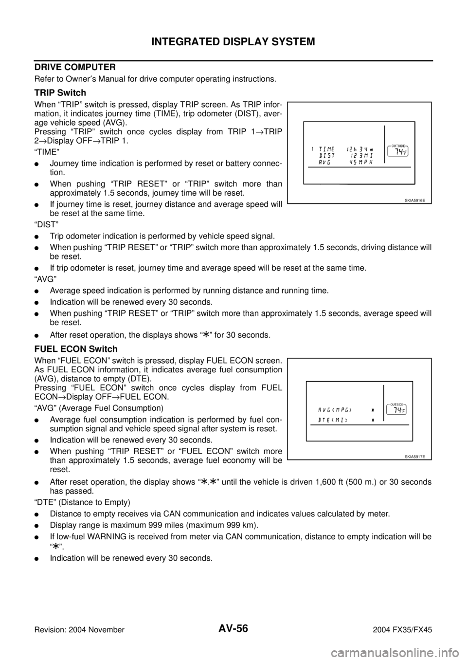
When “TRIP” switch is pressed, display TRIP screen. As TRIP infor-
mation, it indicates journey time (TIME), trip odometer (DIST), aver-
age vehicle speed (AVG).
Pressing “TRIP” switch once cycles display from TRIP 1→TRIP
2→Display OFF→TRIP 1.
“TIME”
�Journey time indication is performed by reset or battery connec-
tion.
�When pushing “TRIP RESET” or “TRIP” switch more than
approximately 1.5 seconds, journey time will be reset.
�If journey time is reset, journey distance and average speed will
be reset at the same time.
“DIST”
�Trip odometer indication is performed by vehicle speed signal.
�When pushing “TRIP RESET” or “TRIP” switch more than approximately 1.5 seconds, driving distance will
be reset.
�If trip odometer is reset, journey time and average speed will be reset at the same time.
“AVG”
�Average speed indication is performed by running distance and running time.
�Indication will be renewed every 30 seconds.
�When pushing “TRIP RESET” or “TRIP” switch more than approximately 1.5 seconds, average speed will
be reset.
�After reset operation, the displays shows “ ” for 30 seconds.
FUEL ECON Switch
When “FUEL ECON” switch is pressed, display FUEL ECON screen.
As FUEL ECON information, it indicates average fuel consumption
(AVG), distance to empty (DTE).
Pressing “FUEL ECON” switch once cycles display from FUEL
ECON→Display OFF→FUEL ECON.
“AVG” (Average Fuel Consumption)
�Average fuel consumption indication is performed by fuel con-
sumption signal and vehicle speed signal after system is reset.
�Indication will be renewed every 30 seconds.
�When pushing “TRIP RESET” or “FUEL ECON” switch more
than approximately 1.5 seconds, average fuel economy will be
reset.
�After reset operation, the display shows “ . ” until the vehicle is driven 1,600 ft (500 m.) or 30 seconds
has passed.
“DTE” (Distance to Empty)
�Distance to empty receives via CAN communication and indicates values calculated by meter.
�Display range is maximum 999 miles (maximum 999 km).
�If low-fuel WARNING is received from meter via CAN communication, distance to empty indication will be
“”.
�Indication will be renewed every 30 seconds.
SKIA5916E
SKIA5917E
Page 669 of 4449

AV-78
INTEGRATED DISPLAY SYSTEM
Revision: 2004 November 2004 FX35/FX45
Trouble Diagnosis Chart by SymptomAKS00BOI
Symptom Check item
No screen is shown.
�Display unit power supply and ground circuit. Refer to AV- 7 9 , "Power Supply
and Ground Circuit Check for Display Unit" .
�Display unit
Screen does not switch to nighttime mode after the
lighting switch is turned ON.
�Illumination signal. Refer to AV-81, "Illumination Signal Inspection" .
�Display unit
TRIP and FUEL ECON screen do not appear.
�Ignition signal. Refer to AV- 8 2 , "Ignition Signal Inspection" .
�Display unit
�Trip odometer (DIST) is not added up.
�Average vehicle speed (AVG) is not displayed.
�Vehicle speed signal. Refer to AV- 8 0 , "Vehicle Speed Signal Inspection" .
�Display unit
Average fuel consumption (AVG) is not displayed.
�Vehicle speed signal. Refer to AV- 8 0 , "Vehicle Speed Signal Inspection" .
�CAN communication line. Refer to AV- 8 5 , "CAN Communication Line Inspec-
tion" .
�Display unit
Distance to empty (DTE) is not displayed.
�Check if speedometer operates. If it does not operate, go to DI-17, "Vehicle
Speed Signal Inspection" .
�Check if fuel gauge operates. If it does not operate, go to DI-20, "Fuel Level
Sensor Signal Inspection 1" .
�CAN communication line. Refer to DI-22, "Communication Line Inspection" .
�Display unit
Tire pressure is not displayed.
�Ignition signal. Refer to AV- 8 2 , "Ignition Signal Inspection" .
�Low tire pressure warning control unit. Refer to WT-17, "Self-Diagnosis" .
�CAN communication line. Refer to DI-22, "Communication Line Inspection" .
�Display unit
Door warning screen does not appear.
�Ignition signal. Refer to AV- 8 2 , "Ignition Signal Inspection" .
�Vehicle speed signal. Refer to AV- 8 0 , "Vehicle Speed Signal Inspection" .
�CAN communication line. Refer to AV- 8 5 , "CAN Communication Line Inspec-
tion" .
�Display unit
A/C and AV switch and all switch operation are not
possible.
(Do not start self-diagnosis.)Refer to AV-84, "
A/C and AV Switch Does Not Operate" .
Air conditioner operation is not possible.
�A/C and AV switch. Refer to AV-41, "A/C and AV Switch Inspection" .
�CAN communication line. Refer to AV- 8 5 , "CAN Communication Line Inspec-
tion" .
Page 1248 of 4449

COMBINATION METERS
DI-5
C
D
E
F
G
H
I
J
L
MA
B
DI
Revision: 2004 November 2004 FX35/FX45
HOW TO CHANGE THE DISPLAY FOR ODO/TRIP METER
�The vehicle speed signal and the memory signals from the meter memory circuit are processed by the
combination meter and the mileage is displayed.
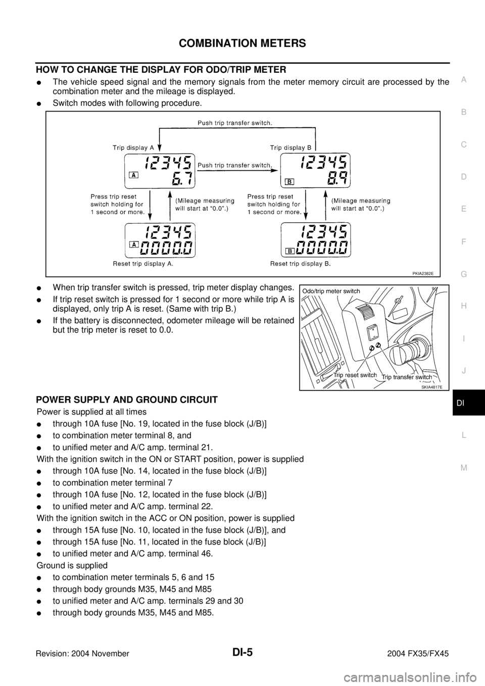
�Switch modes with following procedure.
�When trip transfer switch is pressed, trip meter display changes.
�If trip reset switch is pressed for 1 second or more while trip A is
displayed, only trip A is reset. (Same with trip B.)
�If the battery is disconnected, odometer mileage will be retained
but the trip meter is reset to 0.0.
POWER SUPPLY AND GROUND CIRCUIT
Power is supplied at all times
�through 10A fuse [No. 19, located in the fuse block (J/B)]
�to combination meter terminal 8, and
�to unified meter and A/C amp. terminal 21.
With the ignition switch in the ON or START position, power is supplied
�through 10A fuse [No. 14, located in the fuse block (J/B)]
�to combination meter terminal 7
�through 10A fuse [No. 12, located in the fuse block (J/B)]
�to unified meter and A/C amp. terminal 22.
With the ignition switch in the ACC or ON position, power is supplied
�through 15A fuse [No. 10, located in the fuse block (J/B)], and
�through 15A fuse [No. 11, located in the fuse block (J/B)]
�to unified meter and A/C amp. terminal 46.
Ground is supplied
�to combination meter terminals 5, 6 and 15
�through body grounds M35, M45 and M85
�to unified meter and A/C amp. terminals 29 and 30
�through body grounds M35, M45 and M85.
PKIA2382E
SKIA4817E