Page 1264 of 4449

COMBINATION METERS
DI-21
C
D
E
F
G
H
I
J
L
MA
B
DI
Revision: 2004 November 2004 FX35/FX45
4. CHECK FUEL LEVEL SENSOR (MAIN·SUB) CIRCUIT
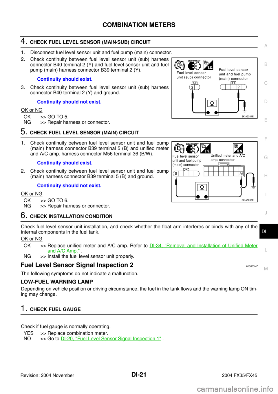
1. Disconnect fuel level sensor unit and fuel pump (main) connector.
2. Check continuity between fuel level sensor unit (sub) harness
connector B40 terminal 2 (Y) and fuel level sensor unit and fuel
pump (main) harness connector B39 terminal 2 (Y).
3. Check continuity between fuel level sensor unit (sub) harness
connector B40 terminal 2 (Y) and ground.
OK or NG
OK >> GO TO 5.
NG >> Repair harness or connector.
5. CHECK FUEL LEVEL SENSOR (MAIN) CIRCUIT
1. Check continuity between fuel level sensor unit and fuel pump
(main) harness connector B39 terminal 5 (B) and unified meter
and A/C amp. harness connector M56 terminal 36 (B/W).
2. Check continuity between fuel level sensor unit and fuel pump
(main) harness connector B39 terminal 5 (B) and ground.
OK or NG
OK >> GO TO 6.
NG >> Repair harness or connector.
6. CHECK INSTALLATION CONDITION
Check fuel level sensor unit installation, and check whether the float arm interferes or binds with any of the
internal components in the fuel tank.
OK or NG
OK >> Replace unified meter and A/C amp. Refer to DI-34, "Removal and Installation of Unified Meter
and A/C Amp." .
NG >> Install the fuel level sensor unit properly.
Fuel Level Sensor Signal Inspection 2AKS005MZ
The following symptoms do not indicate a malfunction.
LOW-FUEL WARNING LAMP
Depending on vehicle position or driving circumstance, the fuel in the tank flows and the warning lamp ON tim-
ing may change.
1. CHECK FUEL GAUGE
Check if fuel gauge is normally operating.
YES >> Replace combination meter.
NO >> Go to DI-20, "
Fuel Level Sensor Signal Inspection 1" . Continuity should exist.
Continuity should not exist.
SKIA5204E
Continuity should exist.
Continuity should not exist.
SKIA5205E
Page 1267 of 4449

DI-24
COMBINATION METERS
Revision: 2004 November 2004 FX35/FX45
8. CHECK VOLTAGE SIGNAL OF UNIFIED METER AND A/C AMP.
1. Turn ignition switch OFF and connect unified meter and A/C amp. connector.
2. Turn ignition switch ON.
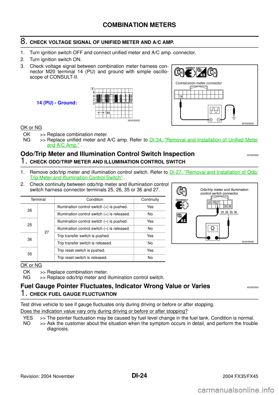
3. Check voltage signal between combination meter harness con-
nector M20 terminal 14 (PU) and ground with simple oscillo-
scope of CONSULT-II.
OK or NG
OK >> Replace combination meter.
NG >> Replace unified meter and A/C amp. Refer to DI-34, "
Removal and Installation of Unified Meter
and A/C Amp." .
Odo/Trip Meter and Illumination Control Switch InspectionAKS005N2
1. CHECK ODO/TRIP METER AND ILLUMINATION CONTROL SWITCH
1. Remove odo/trip meter and illumination control switch. Refer to DI-27, "
Removal and Installation of Odo/
Trip Meter and Illumination Control Switch" .
2. Check continuity between odo/trip meter and illumination control
switch harness connector terminals 25, 26, 35 or 36 and 27.
OK or NG
OK >> Replace combination meter.
NG >> Replace odo/trip meter and illumination control switch.
Fuel Gauge Pointer Fluctuates, Indicator Wrong Value or VariesAKS005N3
1. CHECK FUEL GAUGE FLUCTUATION
Test drive vehicle to see if gauge fluctuates only during driving or before or after stopping.
Does the indication value vary only during driving or before or after stopping?
YES >> The pointer fluctuation may be caused by fuel level change in the fuel tank. Condition is normal.
NO >> Ask the customer about the situation when the symptom occurs in detail, and perform the trouble
diagnosis. 14 (PU) - Ground:
SKIA9260ESKIA3362E
Terminal Condition Continuity
26
27Illumination control switch (+) is pushed. Yes
Illumination control switch (+) is released. No
25Illumination control switch (–) is pushed. Yes
Illumination control switch (–) is released. No
36Trip transfer switch is pushed. Yes
Trip transfer switch is released. No
35Trip reset switch is pushed. Yes
Trip reset switch is released. No
SKIA4846E
Page 1268 of 4449

COMBINATION METERS
DI-25
C
D
E
F
G
H
I
J
L
MA
B
DI
Revision: 2004 November 2004 FX35/FX45
Fuel Gauge Does Not Move to FULL positionAKS005N4
1. QUESTION 1
Does it take a long time for the pointer to move to FULL position?
YES >> GO TO 2.
NO >> GO TO 3.
2. QUESTION 2
Was the vehicle fueled with the ignition switch ON?
YES >> Be sure to fuel the vehicle with the ignition switch OFF. Otherwise, it will take a long time to move
to FULL position because of the characteristic of the fuel gauge.
NO >> GO TO 3.
3. QUESTION 3
Is the vehicle parked on an incline?
YES >> Check the fuel level indication with vehicle on a level surface.
NO >> GO TO 4.
4. QUESTION 4
During driving, does the fuel gauge pointer move gradually toward EMPTY position?
YES >> Check the fuel level sensor unit. Refer to DI-25, "CHECK FUEL LEVEL SENSOR UNIT" .
NO >> The float arm may interfere or bind with any of the components in the fuel tank.
Electrical Components InspectionAKS005N5
CHECK FUEL LEVEL SENSOR UNIT
For removal, refer to FL-4, "FUEL LEVEL SENSOR UNIT, FUEL FILTER AND FUEL PUMP ASSEMBLY" .
Check Fuel Level Sensor Unit and Fuel Pump (Main)
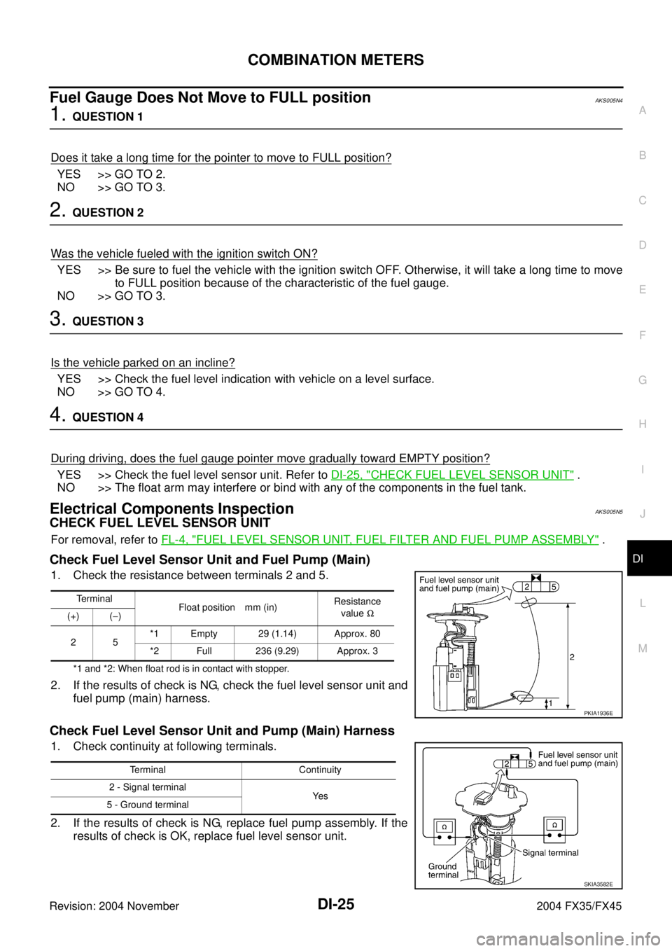
1. Check the resistance between terminals 2 and 5.
*1 and *2: When float rod is in contact with stopper.
2. If the results of check is NG, check the fuel level sensor unit and
fuel pump (main) harness.
Check Fuel Level Sensor Unit and Pump (Main) Harness
1. Check continuity at following terminals.
2. If the results of check is NG, replace fuel pump assembly. If the
results of check is OK, replace fuel level sensor unit.
Terminal
Float position mm (in)Resistance
value Ω
(+) (−)
25*1 Empty 29 (1.14) Approx. 80
*2 Full 236 (9.29) Approx. 3
PKIA1936E
Terminal Continuity
2 - Signal terminal
Ye s
5 - Ground terminal
SKIA3582E
Page 1619 of 4449
EC-278
[VQ35DE]
DTC P0181 FTT SENSOR
Revision: 2004 November 2004 FX35/FX45
2. Check resistance between fuel level sensor unit and fuel pump
terminals 4 and 5 by heating with hot water or heat gun as
shown in the figure.
Removal and InstallationABS006PC
FUEL TANK TEMPERATURE SENSOR
Refer to FL-4, "FUEL LEVEL SENSOR UNIT, FUEL FILTER AND FUEL PUMP ASSEMBLY" .
Temperature °C (°F) Resistance kΩ
20 (68) 2.3 - 2.7
50 (122) 0.79 - 0.90
PBIB0931E
Page 1624 of 4449
DTC P0182, P0183 FTT SENSOR
EC-283
[VQ35DE]
C
D
E
F
G
H
I
J
K
L
MA
EC
Revision: 2004 November 2004 FX35/FX45
2. Check resistance between fuel level sensor unit and fuel pump
terminals 4 and 5 by heating with hot water or heat gun as
shown in the figure.
Removal and InstallationABS006PJ
FUEL TANK TEMPERATURE SENSOR
Refer to FL-4, "FUEL LEVEL SENSOR UNIT, FUEL FILTER AND FUEL PUMP ASSEMBLY" .
Temperature °C (°F) Resistance kΩ
20 (68) 2.3 - 2.7
50 (122) 0.79 - 0.90
PBIB0931E
Page 1710 of 4449
![INFINITI FX35 2004 Service Manual DTC P0455 EVAP CONTROL SYSTEM
EC-369
[VQ35DE]
C
D
E
F
G
H
I
J
K
L
MA
EC
Revision: 2004 November 2004 FX35/FX45
5. CHECK EVAP PURGE LINE
Check EVAP purge line (pipe, rubber tube, fuel tank and EVAP can INFINITI FX35 2004 Service Manual DTC P0455 EVAP CONTROL SYSTEM
EC-369
[VQ35DE]
C
D
E
F
G
H
I
J
K
L
MA
EC
Revision: 2004 November 2004 FX35/FX45
5. CHECK EVAP PURGE LINE
Check EVAP purge line (pipe, rubber tube, fuel tank and EVAP can](/manual-img/42/57021/w960_57021-1709.png)
DTC P0455 EVAP CONTROL SYSTEM
EC-369
[VQ35DE]
C
D
E
F
G
H
I
J
K
L
MA
EC
Revision: 2004 November 2004 FX35/FX45
5. CHECK EVAP PURGE LINE
Check EVAP purge line (pipe, rubber tube, fuel tank and EVAP canister) for cracks, improper connection or
disconnection.
Refer to EC-644, "
EVAPORATIVE EMISSION LINE DRAWING" .
OK or NG
OK >> GO TO 6.
NG >> Repair or reconnect the hose.
6. CLEAN EVAP PURGE LINE
Clean EVAP purge line (pipe and rubber tube) using air blower.
>> GO TO 7.
7. CHECK EVAP CANISTER VENT CONTROL VALVE
Check the following.
�EVAP canister vent control valve is installed properly.
Refer to EC-647, "
Removal and Installation" .
�EVAP canister vent control valve.
Refer to EC-347, "
Component Inspection" .
OK or NG
OK >> GO TO 8.
NG >> Repair or replace EVAP canister vent control valve and O-ring.
8. INSTALL THE PRESSURE PUMP
To locate the EVAP leak, install EVAP service port adapter and pres-
sure pump to EVAP service port securely.
NOTE:
Improper installation of the EVAP service port adapter to the
EVAP service port may cause leaking.
Models with CONSULT-II>>GO TO 9.
Models without CONSULT-II>>GO TO 10.
PBIB2006E
SEF916U
Page 1728 of 4449
![INFINITI FX35 2004 Service Manual DTC P0461 FUEL LEVEL SENSOR
EC-387
[VQ35DE]
C
D
E
F
G
H
I
J
K
L
MA
EC
Revision: 2004 November 2004 FX35/FX45
7. Check “FUEL LEVEL SE” output voltage and note it.
8. Select “FUEL PUMP” in “AC INFINITI FX35 2004 Service Manual DTC P0461 FUEL LEVEL SENSOR
EC-387
[VQ35DE]
C
D
E
F
G
H
I
J
K
L
MA
EC
Revision: 2004 November 2004 FX35/FX45
7. Check “FUEL LEVEL SE” output voltage and note it.
8. Select “FUEL PUMP” in “AC](/manual-img/42/57021/w960_57021-1727.png)
DTC P0461 FUEL LEVEL SENSOR
EC-387
[VQ35DE]
C
D
E
F
G
H
I
J
K
L
MA
EC
Revision: 2004 November 2004 FX35/FX45
7. Check “FUEL LEVEL SE” output voltage and note it.
8. Select “FUEL PUMP” in “ACTIVE TEST” mode with CONSULT-
II.
9. Touch ON and drain fuel approximately 30 (7-7/8 US gal, 6-5/
8 Imp gal) and stop it.
10. Check “FUEL LEVEL SE” output voltage and note it.
11. Fill fuel into the fuel tank for 30 (7-7/8 US gal, 6-5/8 Imp gal).
12. Check “FUEL LEVEL SE” output voltage and note it.
13. Confirm whether the voltage changes more than 0.03V during
step 7 to 10 and 10 to 12.
If NG, go to EC-387, "
Diagnostic Procedure" .
WITH GST
NOTE:
Start from step 8, if it is possible to confirm that the fuel cannot be drained by 30 (7-7/8 US gal, 6-5/8
Imp gal) in advance.
1. Prepare a fuel container and a spare hose.
2. Release fuel pressure from fuel line. Refer to EC-51, "
FUEL PRESSURE RELEASE" .
3. Remove the fuel feed hose on the fuel level sensor unit.
4. Connect a spare fuel hose where the fuel feed hose was removed.
5. Turn ignition switch ON.
6. Drain fuel by 30 (7-7/8 US gal, 6-5/8 Imp gal) from the fuel tank using proper equipment.
7. Confirm that the fuel gauge indication varies.
8. Fill fuel into the fuel tank for 30 (7-7/8 US gal, 6-5/8 Imp gal).
9. Confirm that the fuel gauge indication varies.
10. If NG, go to EC-387, "
Diagnostic Procedure" .
Diagnostic ProcedureABS006S1
1. CHECK DTC WITH “UNIFIED METER AND A/C AMP.”
Refer to DI-32, "
SELF-DIAGNOSTIC RESULTS" .
OK or NG
OK >> GO TO 2.
NG >> Go to DI-20, "
Fuel Level Sensor Signal Inspection 1" .
2. CHECK INTERMITTENT INCIDENT
Refer to EC-135, "
TROUBLE DIAGNOSIS FOR INTERMITTENT INCIDENT" .
>>INSPECTION END
Removal and InstallationABS006S2
FUEL LEVEL SENSOR
Refer to FL-4, "FUEL LEVEL SENSOR UNIT, FUEL FILTER AND FUEL PUMP ASSEMBLY" .
SEF195Y
Page 2277 of 4449
EC-936
[VK45DE]
DTC P0181 FTT SENSOR
Revision: 2004 November 2004 FX35/FX45
Component InspectionABS00C47
FUEL TANK TEMPERATURE SENSOR
1. Remove fuel level sensor unit.
2. Check resistance between “fuel level sensor unit and fuel pump”
terminals 4 and 5 by heating with hot water or heat gun as
shown in the figure.
Removal and InstallationABS00C48
FUEL TANK TEMPERATURE SENSOR
Refer to FL-4, "FUEL LEVEL SENSOR UNIT, FUEL FILTER AND FUEL PUMP ASSEMBLY" .
Temperature °C (°F) Resistance kΩ
20 (68) 2.3 - 2.7
50 (122) 0.79 - 0.90
PBIB0931E