Page 89 of 4449

AT-12
A/T FLUID
Revision: 2004 November 2004 FX35/FX45
A/T FLUIDPFP:KLE40
Changing A/T FluidACS0079Z
1. Warm up ATF.
2. Stop engine.
3. Loosen the level gauge bolt.
4. Drain ATF from drain plug and refill with new ATF. Always refill
same volume with drained fluid.
�To replace the ATF, pour in new fluid at the charging pipe with
the engine idling and at the same time drain the old fluid from
the radiator cooler hose return side.
�When the color of the fluid coming out is about the same as
the color of the new fluid, the replacement is complete. The
amount of new transmission fluid to use should be 30 to 50%
increase of the stipulated amount.
CAUTION:
�Use only Genuine Nissan Matic J ATF. Do not mix with other fluid.
�Using automatic transmission fluid other than Genuine Nissan Matic J ATF will cause deteriora-
tion in drive ability and automatic transmission durability, and may damage the automatic trans-
mission, which is not covered by the warranty.
�When filling ATF, take care not to splash heat generating parts such as exhaust with ATF.
�Do not reuse drain plug gasket.
5. Run engine at idle speed for 5 minutes.
6. Check fluid level and condition. Refer to AT- 1 2 , "
Checking A/T Fluid" . If fluid is still dirty, repeat step 2
through 5.
7. Install the removed A/T fluid level gauge in the A/T fluid charging pipe.
8. Tighten the level gauge bolt.
Checking A/T FluidACS007A0
1. Warm up engine.
2. Check for fluid leakage.
3. Loosen the level gauge bolt.
4. Before driving, fluid level can be checked at fluid temperatures
of 30 to 50°C (86 to 122°F) using “COLD” range on A/T fluid
level gauge as follows.
a. Park vehicle on level surface and set parking brake.
b. Start engine and move selector lever through each gear posi-
tion. Leave selector lever in “P” position.
c. Check fluid level with engine idling.
d. Remove A/T fluid level gauge and wipe clean with lint-free
paper.
CAUTION:
When wiping away the A/T fluid level gauge, always use
lint-free paper, not a cloth one.A/T fluid: Genuine Nissan Matic J ATF
Fluid capacity: 10.3 (10-7/8 US qt, 9-1/8 lmp qt)
Drain plug:
: 34 N·m (3.5 kg-m, 25 ft-lb)
Level gauge bolt:
: 5.1 N·m (0.52 kg-m, 45 in-lb)
SCIA4896E
SCIA4835E
Page 91 of 4449

AT-14
A/T FLUID
Revision: 2004 November 2004 FX35/FX45
10. Tighten the level gauge bolt.
A/T Fluid Cooler CleaningACS007A1
Whenever an automatic transmission is replaced, the A/T fluid cooler mounted in the radiator must be
inspected and cleaned.
Metal debris and friction material, if present, can become trapped in the A/T fluid cooler. This debris can con-
taminate the newly serviced A/T or, in severe cases, can block or restrict the flow of A/T fluid. In either case,
malfunction of the newly serviced A/T may result.
Debris, if present, may build up as A/T fluid enters the cooler inlet. It will be necessary to back flush the cooler
through the cooler outlet in order to flush out any built up debris.
A/T FLUID COOLER CLEANING PROCEDURE
1. Position an oil pan under the automatic transmission's inlet and outlet cooler hoses.
2. Identify the inlet and outlet fluid cooler hoses.
3. Disconnect the fluid cooler inlet and outlet rubber hoses from the
steel cooler tubes or bypass valve.
NOTE:
Replace the cooler hoses if rubber material from the hose
remains on the tube fitting.
4. Allow any A/T fluid that remains in the cooler hoses to drain into
the oil pan.
5. Insert the extension adapter hose of a can of the Transmission
Cooler Cleaner (Nissan P/N 999MP-AM006) into the cooler out-
let hose.
CAUTION:
�Wear safety glasses and rubber gloves when spraying
the Transmission Cooler Cleaner.
�Spray the Transmission Cooler Cleaner only with ade-
quate ventilation.
�Avoid contact with eyes and skin.
�Do not breath vapors or spray mist.
6. Hold the hose and can as high as possible and spray the Trans-
mission Cooler Cleaner in a continuous stream into the cooler outlet hose until fluid flows out of the cooler
inlet hose for 5 seconds.Level gauge bolt:
: 5.1N·m (0.52 kg-m, 45 in-lb)
SCIA4896E
SCIA3830E
SCIA3831E
Page 319 of 4449
AT-242
ON-VEHICLE SERVICE
Revision: 2004 November 2004 FX35/FX45
ON-VEHICLE SERVICEPFP:00000
Control Valve with TCM and A/T Fluid Temperature Sensor 2ACS007GZ
COMPONENTS
CONTROL VALVE WITH TCM REMOVAL AND INSTALLATION
Removal
1. Disconnect the battery cable from the negative terminal.
2. Remove front cross bar. Refer to FSU-8, "
Components" .
3. Disconnect heated oxygen sensor 2 harness connector.
4. Drain ATF through drain plug.
5. Disconnect A/T assembly harness connector.
1. Transmission 2. Control valve with TCM 3. Bracket
4. A/T fluid temperature sensor 2 5. Oil pan gasket 6. Oil pan
7. Magnet 8. Drain plug gasket 9. Drain plug
10. Oil pan mounting bolt 11. Snap ring 12. O-ring
SCIA5137E
Page 326 of 4449

ON-VEHICLE SERVICE
AT-249
D
E
F
G
H
I
J
K
L
MA
B
AT
Revision: 2004 November 2004 FX35/FX45
c. Tighten oil pan mounting bolts to the specified torque in numeri-
cal order as shown in the figure after temporarily tightening
them.
CAUTION:
Do not reuse oil pan mounting bolts.
13. Install drain plug to oil pan.
CAUTION:
Do not reuse drain plug gasket.
14. Pull up A/T assembly harness connector.
CAUTION:
Be careful not to damage connector.
15. Install snap ring to A/T assembly harness connector.
16. Connect A/T assembly harness connector.
17. Connect heated oxygen sensor 2 harness connector.
18. Install front cross bar. Refer to FSU-8, "
Components" .
19. Pour ATF into transmission assembly. Refer to AT- 1 2 , "
Chang-
ing A/T Fluid" .
20. Connect the battery cable to the negative terminal.
A/T FLUID TEMPERATURE SENSOR 2 REMOVAL AND INSTALLATION
Removal
1. Disconnect the battery cable from the negative terminal.
2. Remove front cross bar. Refer to FSU-8, "
Components" .
3. Disconnect heated oxygen sensor 2 harness connector.
4. Drain ATF through drain plug.
5. Remove oil pan and oil pan gasket.: 7.9 N·m (0.81 kg-m, 70 in-lb)
: 34 N·m (3.5 kg-m, 25 ft-lb)
SCIA2492E
SCIA5038E
SCIA5039E
SCIA2308E
Page 329 of 4449
AT-252
ON-VEHICLE SERVICE
Revision: 2004 November 2004 FX35/FX45
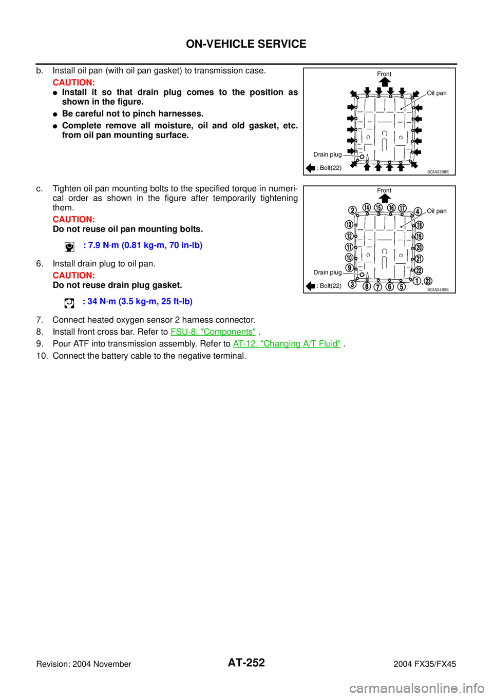
b. Install oil pan (with oil pan gasket) to transmission case.
CAUTION:
�Install it so that drain plug comes to the position as
shown in the figure.
�Be careful not to pinch harnesses.
�Complete remove all moisture, oil and old gasket, etc.
from oil pan mounting surface.
c. Tighten oil pan mounting bolts to the specified torque in numeri-
cal order as shown in the figure after temporarily tightening
them.
CAUTION:
Do not reuse oil pan mounting bolts.
6. Install drain plug to oil pan.
CAUTION:
Do not reuse drain plug gasket.
7. Connect heated oxygen sensor 2 harness connector.
8. Install front cross bar. Refer to FSU-8, "
Components" .
9. Pour ATF into transmission assembly. Refer to AT- 1 2 , "
Changing A/T Fluid" .
10. Connect the battery cable to the negative terminal.
SCIA2308E
: 7.9 N·m (0.81 kg-m, 70 in-lb)
: 34 N·m (3.5 kg-m, 25 ft-lb)
SCIA2492E
Page 330 of 4449
ON-VEHICLE SERVICE
AT-253
D
E
F
G
H
I
J
K
L
MA
B
AT
Revision: 2004 November 2004 FX35/FX45
Parking Components (2WD Models Only)ACS007H0
COMPONENTS
REMOVAL
1. Drain ATF through drain plug.
2. Remove exhaust front tube and center muffler with power tool. Refer to EX-3, "
Removal and Installation" .
3. Remove rear propeller shaft. Refer to PR-7, "
Removal and Installation" .
4. Support transmission assembly with a transmission jack.
CAUTION:
When setting transmission jack, be careful not to allow it to collide against the drain plug.
5. Remove engine rear member with power tool. Refer to AT- 2 6 6 , "
Removal and Installation (2WD Models)"
.
1. Rear oil seal 2. Rear extension 3. Parking actuator support
4. Parking pawl 5. Return spring 6. Pawl shaft
7. Self-sealing bolt 8. Seal ring 9. Parking gear
10. Output shaft 11. Bearing race 12. Needle bearing
SCIA5216E
Page 335 of 4449

AT-258
ON-VEHICLE SERVICE
Revision: 2004 November 2004 FX35/FX45
9. Install bearing race to output shaft.
10. Apply recommended sealant (Genuine Anaerobic Liquid Gasket
or equivalent. Refer to GI-48, "
Recommended Chemical Prod-
ucts and Sealants" .) to rear extension assembly as shown in
illustration.
CAUTION:
Complete remove all moisture, oil and old sealant, etc. from
the transmission case and rear extension assembly mount-
ing surfaces.
11. Install rear extension assembly to transmission case. (With nee-
dle bearing.)
12. Tighten rear extension assembly mounting bolts to specified
torque.
CAUTION:
Do not reuse self-sealing bolt.
13. Install engine rear member. Refer to AT- 2 6 6 , "
Removal and Installation (2WD Models)" .
14. Install rear propeller shaft. Refer to PR-7, "
Removal and Installation" .
15. Install exhaust front tube and center muffler. Refer to EX-3, "
Removal and Installation" .
16. Install drain plug in oil pan.
CAUTION:
Do not reuse drain plug gasket.
17. Pour ATF into transmission assembly. Refer to AT- 1 2 , "
Changing A/T Fluid" .
SCIA5245E
SCIA5212E
SCIA3431E
Rear extension assembly mounting bolt
: 52 N·m (5.3 Kg-m, 38 ft-lb)
Self-sealing bolt
: 61 N·m (6.2 Kg-m, 45 ft-lb)
SCIA3426E
: 34 N·m (3.5 kg-m, 25 ft-lb)
Page 337 of 4449
ACS007H2
COMPONENTS
REMOVAL
1. Disconnect the battery cable from the negative terminal.
2")
AT-260
ON-VEHICLE SERVICE
Revision: 2004 November 2004 FX35/FX45
Revolution Sensor Components (2WD Models Only)ACS007H2
COMPONENTS
REMOVAL
1. Disconnect the battery cable from the negative terminal.
2. Drain ATF through drain plug.
3. Remove front cross bar. Refer to FSU-8, "
Components" .
4. Remove exhaust front tube and center muffler with power tool. Refer to EX-3, "
Removal and Installation" .
5. Remove rear propeller shaft. Refer to PR-7, "
Removal and Installation" .
6. Remove oil pan and oil pan gasket.
7. Support transmission assembly with a transmission jack.
CAUTION:
When setting transmission jack, place wooden blocks to
prevent from damaging control valve with TCM and trans-
mission case.
8. Remove engine rear member with power tool. Refer to AT- 2 6 6 ,
"Removal and Installation (2WD Models)" .
1. Rear extension 2. Transmission 3. Revolution sensor
4. Oil pan gasket 5. Oil pan 6. Oil pan mounting bolt
7. Drain plug gasket 8. Drain plug 9. Self-sealing bolt
SCIA5145E
SCIA2308E

ACS007H0
COMPONENTS
REMOVAL
1. Drain ATF through drain plug.
2. Remove ex")