Page 821 of 4449

BL-14
HOOD
Revision: 2004 November 2004 FX35/FX45
HOODPFP:F5100
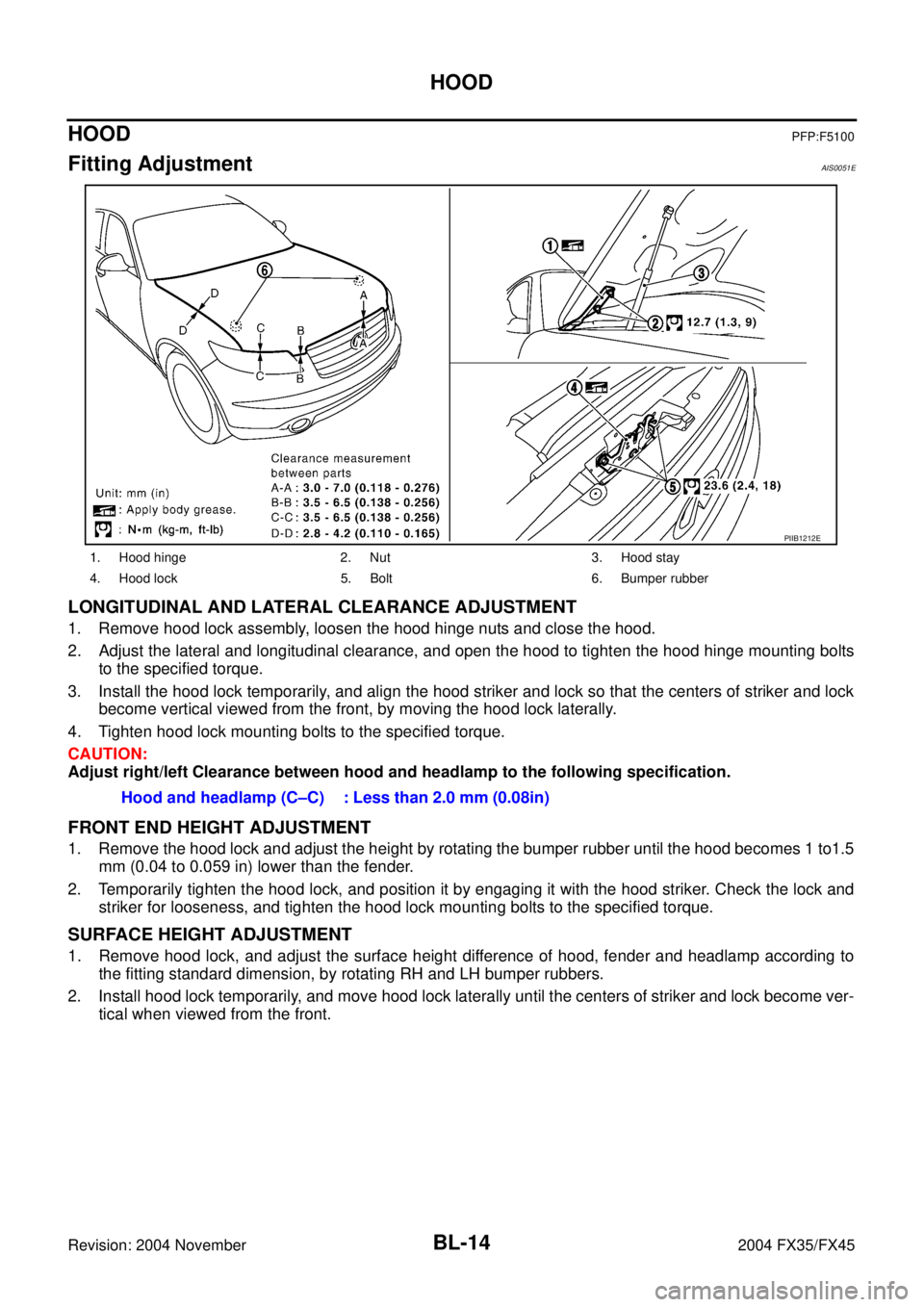
Fitting AdjustmentAIS0051E
LONGITUDINAL AND LATERAL CLEARANCE ADJUSTMENT
1. Remove hood lock assembly, loosen the hood hinge nuts and close the hood.
2. Adjust the lateral and longitudinal clearance, and open the hood to tighten the hood hinge mounting bolts
to the specified torque.
3. Install the hood lock temporarily, and align the hood striker and lock so that the centers of striker and lock
become vertical viewed from the front, by moving the hood lock laterally.
4. Tighten hood lock mounting bolts to the specified torque.
CAUTION:
Adjust right/left Clearance between hood and headlamp to the following specification.
FRONT END HEIGHT ADJUSTMENT
1. Remove the hood lock and adjust the height by rotating the bumper rubber until the hood becomes 1 to1.5
mm (0.04 to 0.059 in) lower than the fender.
2. Temporarily tighten the hood lock, and position it by engaging it with the hood striker. Check the lock and
striker for looseness, and tighten the hood lock mounting bolts to the specified torque.
SURFACE HEIGHT ADJUSTMENT
1. Remove hood lock, and adjust the surface height difference of hood, fender and headlamp according to
the fitting standard dimension, by rotating RH and LH bumper rubbers.
2. Install hood lock temporarily, and move hood lock laterally until the centers of striker and lock become ver-
tical when viewed from the front.
1. Hood hinge 2. Nut 3. Hood stay
4. Hood lock 5. Bolt 6. Bumper rubber
PIIB1212E
Hood and headlamp (C–C) : Less than 2.0 mm (0.08in)
Page 822 of 4449

HOOD
BL-15
C
D
E
F
G
H
J
K
L
MA
B
BL
Revision: 2004 November 2004 FX35/FX45
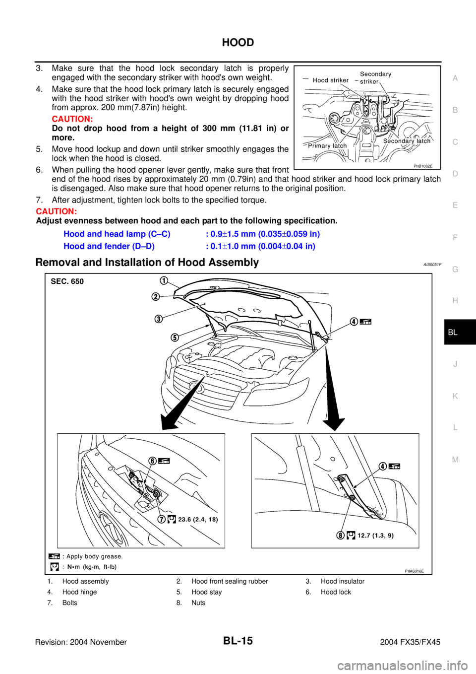
3. Make sure that the hood lock secondary latch is properly
engaged with the secondary striker with hood's own weight.
4. Make sure that the hood lock primary latch is securely engaged
with the hood striker with hood's own weight by dropping hood
from approx. 200 mm(7.87in) height.
CAUTION:
Do not drop hood from a height of 300 mm (11.81 in) or
more.
5. Move hood lockup and down until striker smoothly engages the
lock when the hood is closed.
6. When pulling the hood opener lever gently, make sure that front
end of the hood rises by approximately 20 mm (0.79in) and that hood striker and hood lock primary latch
is disengaged. Also make sure that hood opener returns to the original position.
7. After adjustment, tighten lock bolts to the specified torque.
CAUTION:
Adjust evenness between hood and each part to the following specification.
Removal and Installation of Hood AssemblyAIS0051F
Hood and head lamp (C–C) : 0.9±1.5 mm (0.035±0.059 in)
Hood and fender (D–D) : 0.1±1.0 mm (0.004±0.04 in)
PIIB1082E
1. Hood assembly 2. Hood front sealing rubber 3. Hood insulator
4. Hood hinge 5. Hood stay 6. Hood lock
7. Bolts 8. Nuts
PIIA6016E
Page 826 of 4449

RADIATOR CORE SUPPORT
BL-19
C
D
E
F
G
H
J
K
L
MA
B
BL
Revision: 2004 November 2004 FX35/FX45
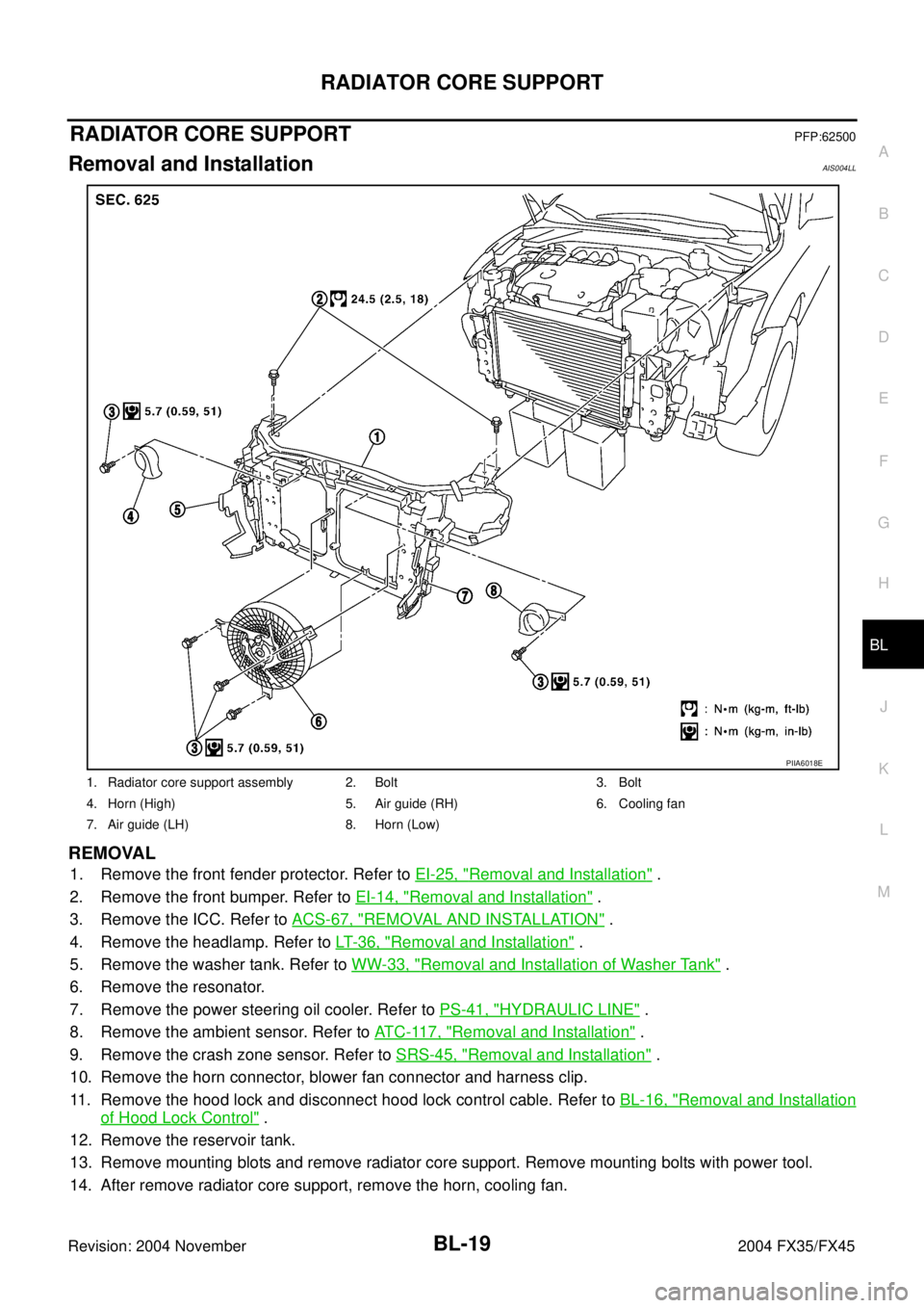
RADIATOR CORE SUPPORTPFP:62500
Removal and InstallationAIS004LL
REMOVAL
1. Remove the front fender protector. Refer to EI-25, "Removal and Installation" .
2. Remove the front bumper. Refer to EI-14, "
Removal and Installation" .
3. Remove the ICC. Refer to ACS-67, "
REMOVAL AND INSTALLATION" .
4. Remove the headlamp. Refer to LT- 3 6 , "
Removal and Installation" .
5. Remove the washer tank. Refer to WW-33, "
Removal and Installation of Washer Tank" .
6. Remove the resonator.
7. Remove the power steering oil cooler. Refer to PS-41, "
HYDRAULIC LINE" .
8. Remove the ambient sensor. Refer to AT C - 11 7 , "
Removal and Installation" .
9. Remove the crash zone sensor. Refer to SRS-45, "
Removal and Installation" .
10. Remove the horn connector, blower fan connector and harness clip.
11. Remove the hood lock and disconnect hood lock control cable. Refer to BL-16, "
Removal and Installation
of Hood Lock Control" .
12. Remove the reservoir tank.
13. Remove mounting blots and remove radiator core support. Remove mounting bolts with power tool.
14. After remove radiator core support, remove the horn, cooling fan.
1. Radiator core support assembly 2. Bolt 3. Bolt
4. Horn (High) 5. Air guide (RH) 6. Cooling fan
7. Air guide (LH) 8. Horn (Low)
PIIA6018E
Page 828 of 4449
FRONT FENDER
BL-21
C
D
E
F
G
H
J
K
L
MA
B
BL
Revision: 2004 November 2004 FX35/FX45
FRONT FENDERPFP:63100
Removal and InstallationAIS004LM
REMOVAL
1. Remove the front bumper. Refer to EI-14, "Removal and Installation" .
2. Remove the headlamp. Refer to LT- 3 6 , "
Removal and Installation" .
3. Remove the front fender protector. Refer to EI-25, "
Removal and Installation" .
4. Remove the mounting bolt and remove the front fender.
CAUTION:
While removing use a shop cloth to protect body from damaging.
INSTALLATION
Install in the reverse order of removal.
CAUTION:
�After installing, apply touch-up paint (the body color) onto the head of the front fender mounting
bolts.
�After installing, check front fender adjustment. Refer to BL-14, "Fitting Adjustment" and BL-148,
"Fitting Adjustment" .
1. Front fender 2. Bolt
PIIA6076E
Page 956 of 4449

DOOR
BL-149
C
D
E
F
G
H
J
K
L
MA
B
BL
Revision: 2004 November 2004 FX35/FX45
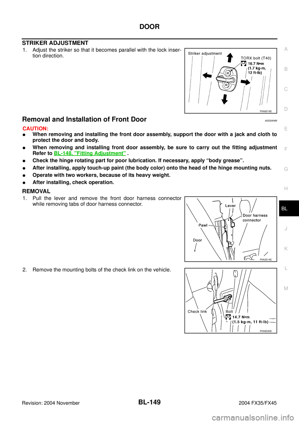
STRIKER ADJUSTMENT
1. Adjust the striker so that it becomes parallel with the lock inser-
tion direction.
Removal and Installation of Front DoorAIS004NW
CAUTION:
�When removing and installing the front door assembly, support the door with a jack and cloth to
protect the door and body.
�When removing and installing front door assembly, be sure to carry out the fitting adjustment
Refer to BL-148, "
Fitting Adjustment" .
�Check the hinge rotating part for poor lubrication. If necessary, apply “body grease”.
�After installing, apply touch-up paint (the body color) onto the head of the hinge mounting nuts.
�Operate with two workers, because of its heavy weight.
�After installing, check operation.
REMOVAL
1. Pull the lever and remove the front door harness connector
while removing tabs of door harness connector.
2. Remove the mounting bolts of the check link on the vehicle.
PIIA6019E
PIIA2514E
PIIA6020E
Page 957 of 4449
BL-150
DOOR
Revision: 2004 November 2004 FX35/FX45
3. Remove the door-side hinge mounting nuts, and remove the
door assembly.
INSTALLATION
Install in the reverse order of removal.
Removal and Installation of Rear DoorAIS004NX
CAUTION:
�When removing and installing the rear door assembly, support the door with a jack and cloth to
protect the door and body.
�When removing and installing rear door assembly, be sure to carry out the fitting adjustment Refer
to BL-148, "
Fitting Adjustment" .
�Check the hinge rotating part for poor lubrication. If necessary, apply “body grease”.
�After installing, apply touch-up paint (the body color) onto the head of the hinge mounting nuts.
�Operate with two workers, because of its heavy weight.
�After installing, check operation.
REMOVAL
1. Grommet is pulled out, and the Rear door harness connector is
detached.
2. Remove the mounting bolts of the check link on the vehicle.
PIIA6021E
PIIA2787E
PIIA6022E
Page 2731 of 4449
![INFINITI FX35 2004 Service Manual EM-6
[VQ35DE]
PRECAUTIONS
Revision: 2004 November 2004 FX35/FX45
�When tightening nuts and bolts, as a basic rule, equally tighten in several different steps starting with the
ones in center, then one INFINITI FX35 2004 Service Manual EM-6
[VQ35DE]
PRECAUTIONS
Revision: 2004 November 2004 FX35/FX45
�When tightening nuts and bolts, as a basic rule, equally tighten in several different steps starting with the
ones in center, then one](/manual-img/42/57021/w960_57021-2730.png)
EM-6
[VQ35DE]
PRECAUTIONS
Revision: 2004 November 2004 FX35/FX45
�When tightening nuts and bolts, as a basic rule, equally tighten in several different steps starting with the
ones in center, then ones on inside and outside diagonally in this order. If the order of tightening is speci-
fied, do exactly as specified.
�Replace with new liquid gasket, packing, oil seal or O-ring.
�Thoroughly wash, clean, and air-blow each part. Carefully check engine oil or engine coolant passages for
any restriction and blockage.
�Avoid damaging sliding or mating surfaces. Completely remove foreign materials such as cloth lint or dust.
Before assembly, oil sliding surfaces well.
�Release air within route when refilling after draining engine coolant.
�Before starting engine, apply fuel pressure to fuel lines with turning ignition switch “ON” (with engine
stopped). Then make sure that there are no leaks at fuel line connections.
�After repairing, start engine and increase engine speed to check engine coolant, fuel, engine oil and
exhaust systems for leakage.
Parts Requiring Angle TighteningABS005ZP
�Use an angle wrench [SST: KV10112100 (BT8653-A)] for the final tightening of the following engine parts:
–Cylinder head bolts
–Main bearing cap bolts
–Connecting rod cap bolts
–Crankshaft pulley bolt (No angle wrench is required as the bolt flange is provided with notches for angle
tightening)
�Do not use a torque value for final tightening.
�The torque value for these parts are for a preliminary step.
�Ensure thread and seat surfaces are clean and coated with engine oil.
Precautions for Liquid GasketABS005ZQ
REMOVAL OF LIQUID GASKET SEALING
�After removing mounting bolts and nuts, separate the mating
surface using a seal cutter (SST) and remove old liquid gasket
sealing.
CAUTION:
Be careful not to damage the mating surfaces.
�Tap seal cutter to insert it, and then slide it by tapping on the
side as shown in the figure.
�In areas where seal cutter is difficult to use, use plastic hammer
to lightly tap the areas where the liquid gasket is applied.
CAUTION:
If for some unavoidable reason tool such as screwdriver is
used, be careful not to damage the mating surfaces.
LIQUID GASKET APPLICATION PROCEDURE
1. Using a scraper, remove old liquid gasket adhering to liquid gas-
ket application surface and the mating surface.
�Remove liquid gasket completely from the groove of the liquid
gasket application surface, mounting bolts, and bolt holes.
2. Wipe liquid gasket application surface and the mating surface
with white gasoline (lighting and heating use) to remove adher-
ing moisture, grease and foreign materials.
PBIC0002E
PBIC0003E
Page 2734 of 4449
PREPARATION
EM-9
[VQ35DE]
C
D
E
F
G
H
I
J
K
L
MA
EM
Revision: 2004 November 2004 FX35/FX45(J-39386)
Valve oil seal driftInstalling valve oil seal
EM03470000
(J-8037)
Piston ring compressorInstalling piston assembly into cylinder bore
ST16610001
(J-23907)
Pilot bushing pullerRemoving crankshaft pilot converter
KV10111100
(J-37228)
Seal cutterRemoving steel oil pan (lower and upper) and
front and rear timing chain case
WS39930000
(—)
Tube presserPressing tube of liquid gasket
KV10112100
(BT8653-A)
Angle wrenchTightening bolts for bearing cap, cylinder
head, etc. in angle
KV10117100
(J-3647-A)
Heated oxygen sensor wrenchLoosening or tightening heated oxygen
sensor 2
For 22 mm (0.87 in) width hexagon nut Tool number
(Kent-Moore No.)
Tool nameDescription
NT024
NT044
NT045
NT046
NT052
NT014
NT379