Page 4 of 4449

FRONT WHEEL ALIGNMENT (Unladen* )
ELS0003X
* : Fuel, engine coolant and engine oil full. Spare tire, jack, hand tools and mats in designa")
QUICK REFERENCE CHART FX35/FX45
ENGINE TUNE-UP DATA (VK45DE)
FRONT WHEEL ALIGNMENT (Unladen* )
ELS0003X
* : Fuel, engine coolant and engine oil full. Spare tire, jack, hand tools and mats in designated positions.Engine modelVK45DE
Firing order1-8-7-3-6-5-4-2
Idle speed
A/T (In “P” or “N” position) rpm650±50
Ignition timing
(BTDC at idle speed)12°±5°
CO% at idle 0.7 - 9.9 % and engine runs smoothly
Tensions of drive belts Auto adjustment by auto tensioner
Radiater cap relief pressure
kPa (kg/cm
2 , psi)
Standard 78 - 98 (0.8 - 1.0 , 11 - 14 )
Limit 59 (0.6, 9)
Cooling system leakage testing pressure
157(1.6, 23)
kPa (kg/cm
2 , psi)
Compression pressure
kPa (kg/cm
2 , psi)/rpm
Standard 1,320 (13.5, 191) /300
Minimum 1,130 (11.5, 164)/300
Spark plug Standard type PLFR5A - 11
Hot type PLFR4A - 11
Cold type PLFR6A - 11
Camber Degree minute (Decimal degree) Minimum – 1° 29′ ( – 1.48° )
Nominal – 0° 44′ ( – 0.73° )
Maximum 0° 01′ ( 0.02° )
Left and right difference 45′ ( 0.75° ) or less
Caster Degree minute (Decimal degree) Minimum 3° 02′ ( 3.03° )
Nominal 3° 47′ ( 3.78° )
Maximum 4° 32′ ( 4.53° )
Left and right difference 45′ ( 0.75° ) or less
Kingpin inclination Degree minute (Decimal degree) Minimum 12° 20′ ( 12.33° )
Nominal 13° 05′ ( 13.08° )
Maximum 13 50′ ( 13.83° )
Total toe-in Distance (A – B) Minimum 0.6 mm ( 0.024 in )
Nominal 1.6 mm ( 0.063 in )
Maximum 2.6 mm ( 0.102 in )
Angle (left plus right)
Degree minute (Degree)Minimum –
Nominal 6′ ( 0.1° )
Maximum –
Wheel turning angle (Full turn) Inside MInimum 32° 00′ ( 32.0° )
Degree minute (Decimal degree) Nominal 35° 00′ ( 35.0° )
Maximum 36° 00′ ( 36.0° )
Outside
Nominal 30° 00′ ( 30.0° )
Degree minute (Decimal degree)
2004
Page 5 of 4449

ELS0003Y
* : Fuel, engine coolant and engine oil full. Spare tire, jack, hand tools and mats in designated positions.
BRAKEELS0003Z
*")
QUICK REFERENCE CHART FX35/FX45
REAR WHEEL ALIGNMENT (Unladen*)
ELS0003Y
* : Fuel, engine coolant and engine oil full. Spare tire, jack, hand tools and mats in designated positions.
BRAKEELS0003Z
* : Under force of 490 N( 50 kg, 110 lb ) with engine running.
REFILL CAPACITIESELS00040
Camber
Degree minute (Decimal degree)Minimum – 1° 18′ ( – 1.30° )
Nominal – 0° 48′ ( – 0.80° )
Maximum – 0° 18′ ( – 0.30° )
To t a l t o e - i nDistance ( A – B ) Minimum 2.4 mm ( 0.094 in )
Nominal 4.7 mm ( 0.185 in )
Maximum 7.0 mm ( 0.276 in )
Angle (left plus right )
Degree minute (Degree)Minimum 0° 05′ ( 0.08° )
Nominal 0° 10′ ( 0.17° )
Maximum 0° 15′ ( 0.25° )
Front brake Pad wear limit 2.0 mm ( 0.079 in )
Rotor repair limit 26.0 mm ( 1.024 in )
Rear brake Pad wear limit 2.0 mm ( 0.079 in )
Rotor repair limit 14.0 mm ( 0.551 in )
Pedal free height 161.5 - 171.5 mm ( 6.358 - 6.752 in )
Pedal depressed height* More than 80 mm ( 3.15 in )
UNITLiter US measure
Fuel tank90 23 - 3/4 gal
Coolant ( With reservoir tank )VQ35DE 8.6 9 - 1/8 qt
VK45DE 10.0 10 - 5/8 qt
Engine(VQ35DE)Drain and refill
With oil filter change 4.7 5 qt
Without oil filter change 4.4 4 - 5/8 qt
Dry engine (Overhaul) 5.4 5 - 3/4 qt
Engine(VK45DE)Drain and refill
With oil filter change 6.6 7qt
Without oil filter change 6.0 6 - 3/8 qt
Dry engine (Overhaul) 7.7 8 - 1/8 qt
Transmission A/T 10.3 10 - 7/8 qt
Transfer1.25 2 - 5/8 pt
Differential carrierFront 0.65 1 - 3/8 pt
Rear 1.4 3 pt
Power steering system 1.0 1 - 1/8 qt
Air conditioning systemCompressor oil 0.18 6.0 fl oz
Refrigerant 0.55 kg 1.21 lb
2004
Page 1368 of 4449
![INFINITI FX35 2004 Service Manual PREPARATION
EC-27
[VQ35DE]
C
D
E
F
G
H
I
J
K
L
MA
EC
Revision: 2004 November 2004 FX35/FX45
PREPARATIONPFP:00002
Special Service ToolsABS006K2
The actual shapes of Kent-Moore tools may differ from tho](/manual-img/42/57021/w960_57021-1367.png "INFINITI FX35 2004 Service Manual PREPARATION
EC-27
[VQ35DE]
C
D
E
F
G
H
I
J
K
L
MA
EC
Revision: 2004 November 2004 FX35/FX45
PREPARATIONPFP:00002
Special Service ToolsABS006K2
The actual shapes of Kent-Moore tools may differ from tho")
PREPARATION
EC-27
[VQ35DE]
C
D
E
F
G
H
I
J
K
L
MA
EC
Revision: 2004 November 2004 FX35/FX45
PREPARATIONPFP:00002
Special Service ToolsABS006K2
The actual shapes of Kent-Moore tools may differ from those of special service tools illustrated here.
Tool number
(Kent-Moore No.)
Tool nameDescription
EG17650301
(J-33984-A)
Radiator cap tester
adapterAdapting radiator cap tester to radiator cap and
radiator filler neck
a: 28 (1.10) dia.
b: 31.4 (1.236) dia.
c: 41.3 (1.626) dia.
Unit: mm (in)
KV10117100
(J-36471-A)
Heated oxygen
sensor wrenchLoosening or tightening heated oxygen sensors
with 22 mm (0.87 in) hexagon nut
KV10114400
(J-38365)
Heated oxygen
sensor wrenchLoosening or tightening heated oxygen sensors
a: 22 mm (0.87 in)
(J-44321)
Fuel pressure gauge
kitChecking fuel pressure
KV109E0010
(J-46209)
Break-out boxMeasuring the ECM signals with a circuit tester
KV109E0080
(J-45819)
Y-cable adapterMeasuring the ECM signals with a circuit tester
S-NT564
S-NT379
S-NT636
LEC642
S-NT825
S-NT826
Page 1369 of 4449
![INFINITI FX35 2004 Service Manual EC-28
[VQ35DE]
PREPARATION
Revision: 2004 November 2004 FX35/FX45
Commercial Service ToolsABS006K3
Tool name
(Kent-Moore No.)Description
Leak detector
i.e.: (J-41416)Locating the EVAP leak
EVAP servi](/manual-img/42/57021/w960_57021-1368.png "INFINITI FX35 2004 Service Manual EC-28
[VQ35DE]
PREPARATION
Revision: 2004 November 2004 FX35/FX45
Commercial Service ToolsABS006K3
Tool name
(Kent-Moore No.)Description
Leak detector
i.e.: (J-41416)Locating the EVAP leak
EVAP servi")
EC-28
[VQ35DE]
PREPARATION
Revision: 2004 November 2004 FX35/FX45
Commercial Service ToolsABS006K3
Tool name
(Kent-Moore No.)Description
Leak detector
i.e.: (J-41416)Locating the EVAP leak
EVAP service port
adapter
i.e.: (J-41413-OBD)Applying positive pressure through EVAP service
port
Fuel filler cap adapter
i.e.: (MLR-8382)Checking fuel tank vacuum relief valve opening
pressure
Socket wrench Removing and installing engine coolant
temperature sensor
Oxygen sensor thread
cleaner
i.e.: (J-43897-18)
(J-43897-12)Reconditioning the exhaust system threads
before installing a new oxygen sensor. Use with
anti-seize lubricant shown below.
a: 18 mm diameter with pitch 1.5 mm for
Zirconia Oxygen Sensor
b: 12 mm diameter with pitch 1.25 mm for
Titania Oxygen Sensor
Anti-seize lubricant
i.e.: (Permatex
TM
133AR or equivalent
meeting MIL
specification MIL-A-
907)Lubricating oxygen sensor thread cleaning tool
when reconditioning exhaust system threads.
S-NT703
S-NT704
S-NT815
S-NT705
AEM488
S-NT779
Page 1379 of 4449
![INFINITI FX35 2004 Service Manual EC-38
[VQ35DE]
BASIC SERVICE PROCEDURE
Revision: 2004 November 2004 FX35/FX45
2. Connect No. 1 ignition coil and No. 1 spark plug with suitable
high-tension wire as shown, and attach timing light clam](/manual-img/42/57021/w960_57021-1378.png "INFINITI FX35 2004 Service Manual EC-38
[VQ35DE]
BASIC SERVICE PROCEDURE
Revision: 2004 November 2004 FX35/FX45
2. Connect No. 1 ignition coil and No. 1 spark plug with suitable
high-tension wire as shown, and attach timing light clam")
EC-38
[VQ35DE]
BASIC SERVICE PROCEDURE
Revision: 2004 November 2004 FX35/FX45
2. Connect No. 1 ignition coil and No. 1 spark plug with suitable
high-tension wire as shown, and attach timing light clamp to this
wire.
3. Check ignition timing.
Idle Speed/Ignition Timing/Idle Mixture Ratio AdjustmentABS006KD
PREPARATION
1. Make sure that the following parts are in good order.
�Battery
�Ignition system
�Engine oil and coolant levels
�Fuses
�ECM harness connector
�Vacuum hoses
�Air intake system
(Oil filler cap, oil level gauge, etc.)
�Fuel pressure
�Engine compression
�Throttle valve
�Evaporative emission system
2. On air conditioner equipped models, checks should be carried out while the air conditioner is OFF.
3. On automatic transmission equipped models, when checking idle rpm, ignition timing and mixture ratio,
checks should be carried out while shift lever is in N position.
4. When measuring CO percentage, insert probe more than 40 cm (15.7 in) into tail pipe.
5. Turn OFF headlamp, heater blower, rear window defogger.
PBIB1573E
SEF166Y
PBIB1602E
Page 1421 of 4449
EC-80
[VQ35DE]
TROUBLE DIAGNOSIS
Revision: 2004 November 2004 FX35/FX45
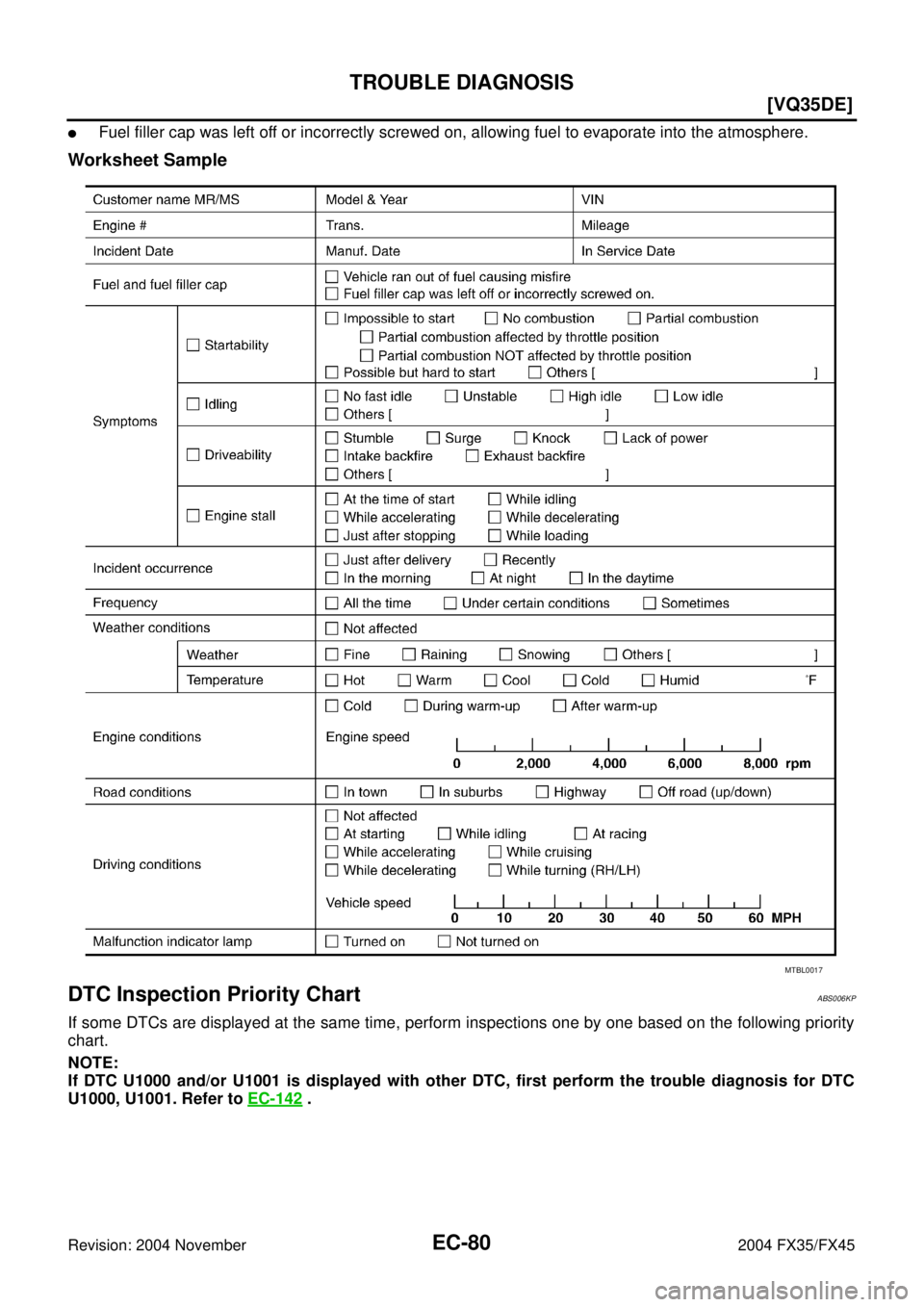
�Fuel filler cap was left off or incorrectly screwed on, allowing fuel to evaporate into the atmosphere.
Worksheet Sample
DTC Inspection Priority ChartABS006KP
If some DTCs are displayed at the same time, perform inspections one by one based on the following priority
chart.
NOTE:
If DTC U1000 and/or U1001 is displayed with other DTC, first perform the trouble diagnosis for DTC
U1000, U1001. Refer to EC-142
.
MTBL0017
Page 1432 of 4449
TROUBLE DIAGNOSIS
EC-91
[VQ35DE]
C
D
E
F
G
H
I
J
K
L
MA
EC
Revision: 2004 November 2004 FX35/FX45
1 - 6: The numbers refer to the order of inspection.Cooling
Radiator/Hose/Radiator filler cap
55555 55 45CO-14
,
CO-17
Thermostat 5CO-26
Water pumpCO-22
Water galleryCO-28
Cooling fan 5EC-203
Coolant level (Low)/Contami-
nated coolant5CO-11
IVIS (Infiniti Vehicle Immobilizer System —
NATS)11EC-68 or
BL-206
SYMPTOM
Reference
page
HARD/NO START/RESTART (EXCP. HA)
ENGINE STALL
HESITATION/SURGING/FLAT SPOT
SPARK KNOCK/DETONATION
LACK OF POWER/POOR ACCELERATION
HIGH IDLE/LOW IDLE
ROUGH IDLE/HUNTING
IDLING VIBRATION
SLOW/NO RETURN TO IDLE
OVERHEATS/WATER TEMPERATURE HIGH
EXCESSIVE FUEL CONSUMPTION
EXCESSIVE OIL CONSUMPTION
BATTERY DEAD (UNDER CHARGE)
Warranty symptom code AA AB AC AD AE AF AG AH AJ AK AL AM HA
Page 1577 of 4449
![INFINITI FX35 2004 Service Manual EC-236
[VQ35DE]
DTC P0138, P0158 HO2S2
Revision: 2004 November 2004 FX35/FX45
DTC P0138, P0158 HO2S2PFP:226A0
Component DescriptionABS006OH
The heated oxygen sensor 2, after three way catalyst 1, moni](/manual-img/42/57021/w960_57021-1576.png "INFINITI FX35 2004 Service Manual EC-236
[VQ35DE]
DTC P0138, P0158 HO2S2
Revision: 2004 November 2004 FX35/FX45
DTC P0138, P0158 HO2S2PFP:226A0
Component DescriptionABS006OH
The heated oxygen sensor 2, after three way catalyst 1, moni")
EC-236
[VQ35DE]
DTC P0138, P0158 HO2S2
Revision: 2004 November 2004 FX35/FX45
DTC P0138, P0158 HO2S2PFP:226A0
Component DescriptionABS006OH
The heated oxygen sensor 2, after three way catalyst 1, monitors the
oxygen level in the exhaust gas on each bank.
Even if switching characteristics of the heated oxygen sensor 1 are
shifted, the air-fuel ratio is controlled to stoichiometric, by the signal
from the heated oxygen sensor 2.
This sensor is made of ceramic zirconia. The zirconia generates volt-
age from approximately 1V in richer conditions to 0V in leaner condi-
tions.
Under normal conditions the heated oxygen sensor 2 is not used for
engine control operation.
CONSULT-II Reference Value in Data Monitor ModeABS006OI
Specification data are reference values.
On Board Diagnosis LogicABS006OJ
The heated oxygen sensor 2 has a much longer switching time
between rich and lean than the heated oxygen sensor 1. The oxygen
storage capacity of the three way catalyst 1 causes the longer
switching time. To judge the malfunctions of heated oxygen sensor
2, ECM monitors whether the voltage is unusually high during the
various driving condition such as fuel-cut.
SEF327R
MONITOR ITEM CONDITION SPECIFICATION
HO2S2 (B1)
HO2S2 (B2)
�Warm-up condition
�After keeping engine speed
between 3,500 and 4,000 rpm for
1 minute and at idle for 1 minute
under no load.Revving engine from idle to 3,000 rpm
quickly.0 - 0.3V ←→ Approx. 0.6 -
1.0V
HO2S2 MNTR (B1)
HO2S2 MNTR (B2)LEAN ←→ RICH
SEF305UA
DTC No. Trouble diagnosis name DTC detecting condition Possible cause
P0138
0138
(Bank 1)
Heated oxygen sensor
2 circuit high voltageAn excessively high voltage from the sensor is
sent to ECM.
�Harness or connectors
(The sensor circuit is open or shorted)
�Heated oxygen sensor 2 P0158
0158
(Bank 2)
![INFINITI FX35 2004 Service Manual TROUBLE DIAGNOSIS
EC-91
[VQ35DE]
C
D
E
F
G
H
I
J
K
L
MA
EC
Revision: 2004 November 2004 FX35/FX45
1 - 6: The numbers refer to the order of inspection.Cooling
Radiator/Hose/Radiator filler cap
55555 55](/manual-img/42/57021/w960_57021-1431.png "INFINITI FX35 2004 Service Manual TROUBLE DIAGNOSIS
EC-91
[VQ35DE]
C
D
E
F
G
H
I
J
K
L
MA
EC
Revision: 2004 November 2004 FX35/FX45
1 - 6: The numbers refer to the order of inspection.Cooling
Radiator/Hose/Radiator filler cap
55555 55")