Page 2016 of 4449
![INFINITI FX35 2004 Service Manual PREPARATION
EC-675
[VK45DE]
C
D
E
F
G
H
I
J
K
L
MA
EC
Revision: 2004 November 2004 FX35/FX45
Commercial Service ToolsABS00BZ2
Tool name
(Kent-Moore No.)Description
Leak detector
i.e.: (J-41416)Locati](/manual-img/42/57021/w960_57021-2015.png "INFINITI FX35 2004 Service Manual PREPARATION
EC-675
[VK45DE]
C
D
E
F
G
H
I
J
K
L
MA
EC
Revision: 2004 November 2004 FX35/FX45
Commercial Service ToolsABS00BZ2
Tool name
(Kent-Moore No.)Description
Leak detector
i.e.: (J-41416)Locati")
PREPARATION
EC-675
[VK45DE]
C
D
E
F
G
H
I
J
K
L
MA
EC
Revision: 2004 November 2004 FX35/FX45
Commercial Service ToolsABS00BZ2
Tool name
(Kent-Moore No.)Description
Leak detector
i.e.: (J-41416)Locating the EVAP leak
EVAP service port
adapter
i.e.: (J-41413-OBD)Applying positive pressure through EVAP service
port
Fuel filler cap adapter
i.e.: (MLR-8382)Checking fuel tank vacuum relief valve opening
pressure
Socket wrench Removing and installing engine coolant
temperature sensor
Oxygen sensor thread
cleaner
i.e.: (J-43897-18)
(J-43897-12)Reconditioning the exhaust system threads
before installing a new oxygen sensor. Use with
anti-seize lubricant shown below.
a: 18 mm diameter with pitch 1.5 mm for
Zirconia Oxygen Sensor
b: 12 mm diameter with pitch 1.25 mm for
Titania Oxygen Sensor
Anti-seize lubricant
i.e.: (Permatex
TM
133AR or equivalent
meeting MIL
specification MIL-A-
907)Lubricating oxygen sensor thread cleaning tool
when reconditioning exhaust system threads.
S-NT703
S-NT704
S-NT815
S-NT705
AEM488
S-NT779
Page 2028 of 4449
BASIC SERVICE PROCEDURE
EC-687
[VK45DE]
C
D
E
F
G
H
I
J
K
L
MA
EC
Revision: 2004 November 2004 FX35/FX45
Idle Speed/Ignition Timing/Idle Mixture Ratio AdjustmentABS00BZD
PREPARATION
1. Make sure that the following parts are in good order.
�Battery
�Ignition system
�Engine oil and coolant levels
�Fuses
�ECM harness connector
�Va c u u m h o s e s
�Air intake system
(Oil filler cap, oil level gauge, etc.)
�Fuel pressure
�Engine compression
�Throttle valve
�Evaporative emission system
2. On air conditioner equipped models, checks should be carried out while the air conditioner is OFF.
3. On automatic transmission equipped models, when checking idle rpm, ignition timing and mixture ratio,
checks should be carried out while shift lever is in N position.
4. When measuring CO percentage, insert probe more than 40 cm (15.7 in) into tail pipe.
5. Turn OFF headlamp, heater blower, rear window defogger.
6. Keep front wheels pointed straight ahead.
Page 2070 of 4449
TROUBLE DIAGNOSIS
EC-729
[VK45DE]
C
D
E
F
G
H
I
J
K
L
MA
EC
Revision: 2004 November 2004 FX35/FX45
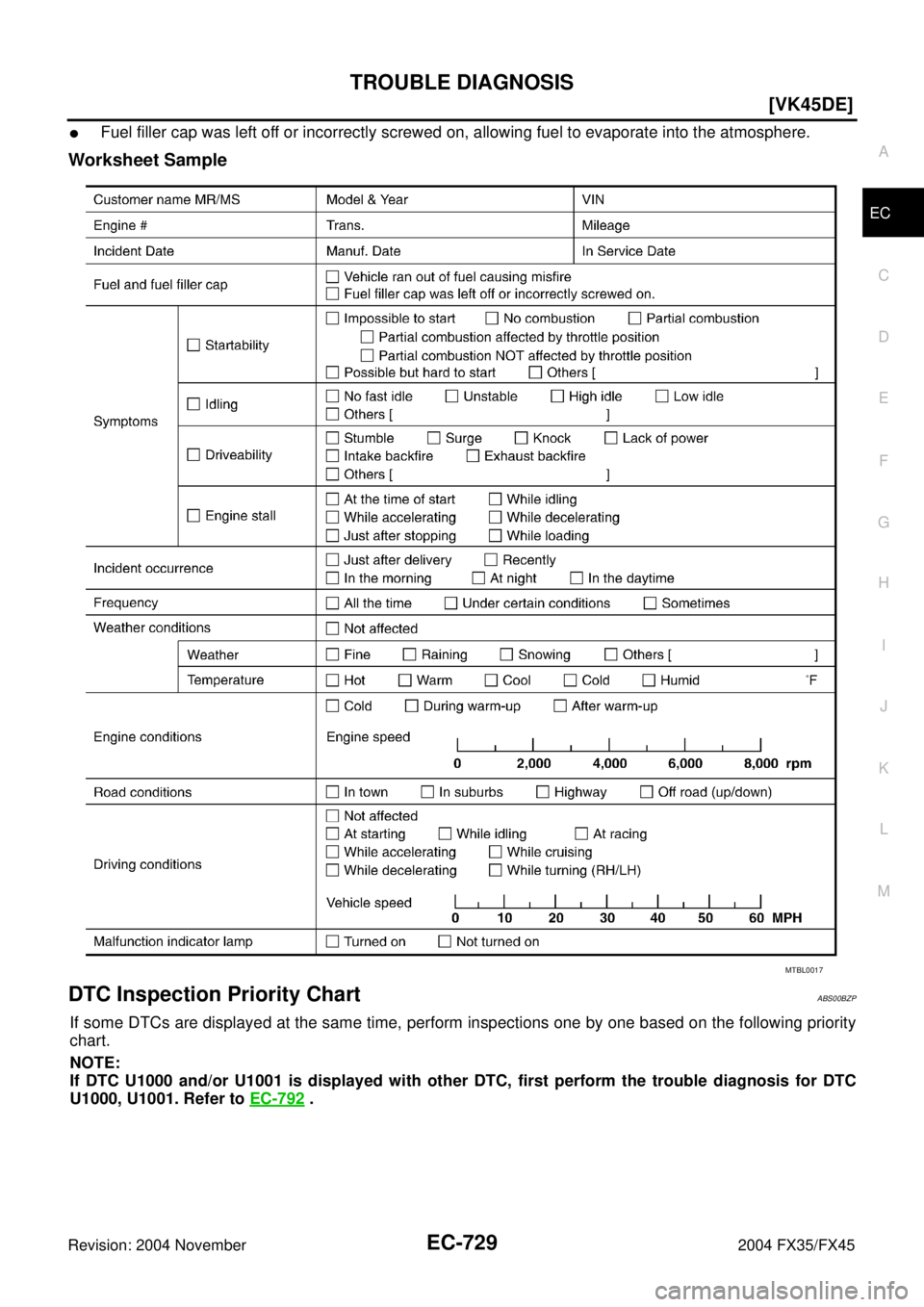
�Fuel filler cap was left off or incorrectly screwed on, allowing fuel to evaporate into the atmosphere.
Worksheet Sample
DTC Inspection Priority ChartABS00BZP
If some DTCs are displayed at the same time, perform inspections one by one based on the following priority
chart.
NOTE:
If DTC U1000 and/or U1001 is displayed with other DTC, first perform the trouble diagnosis for DTC
U1000, U1001. Refer to EC-792
.
MTBL0017
Page 2082 of 4449
![INFINITI FX35 2004 Service Manual TROUBLE DIAGNOSIS
EC-741
[VK45DE]
C
D
E
F
G
H
I
J
K
L
MA
EC
Revision: 2004 November 2004 FX35/FX45
1 - 6: The numbers refer to the order of inspection.Exhaust Exhaust manifold/Tube/Muffler/
Gasket
555](/manual-img/42/57021/w960_57021-2081.png "INFINITI FX35 2004 Service Manual TROUBLE DIAGNOSIS
EC-741
[VK45DE]
C
D
E
F
G
H
I
J
K
L
MA
EC
Revision: 2004 November 2004 FX35/FX45
1 - 6: The numbers refer to the order of inspection.Exhaust Exhaust manifold/Tube/Muffler/
Gasket
555")
TROUBLE DIAGNOSIS
EC-741
[VK45DE]
C
D
E
F
G
H
I
J
K
L
MA
EC
Revision: 2004 November 2004 FX35/FX45
1 - 6: The numbers refer to the order of inspection.Exhaust Exhaust manifold/Tube/Muffler/
Gasket
55555 55 5EM-178
,
EX-3
Three way catalyst
Lubrica-
tionOil pan/Oil strainer/Oil pump/Oil
filter/Oil gallery/Oil cooler
55555 55 5EM-181
,
LU-31
, LU-
28 , LU-29
Oil level (Low)/Filthy oilLU-25
Cooling
Radiator/Hose/Radiator filler cap
55555 55 45CO-39,
CO-43
Thermostat 5CO-51
Water pumpCO-49
Water galleryCO-34
Cooling fan
5CO-47
Coolant level (Low)/Contami-
nated coolantCO-36
IVIS (INFINITI Vehicle Immobilizer System —
NATS)11EC-717 or
BL-206
SYMPTOM
Reference
page
HARD/NO START/RESTART (EXCP. HA)
ENGINE STALL
HESITATION/SURGING/FLAT SPOT
SPARK KNOCK/DETONATION
LACK OF POWER/POOR ACCELERATION
HIGH IDLE/LOW IDLE
ROUGH IDLE/HUNTING
IDLING VIBRATION
SLOW/NO RETURN TO IDLE
OVERHEATS/WATER TEMPERATURE HIGH
EXCESSIVE FUEL CONSUMPTION
EXCESSIVE OIL CONSUMPTION
BATTERY DEAD (UNDER CHARGE)
Warranty symptom code AA AB AC AD AE AF AG AH AJ AK AL AM HA
Page 2235 of 4449
![INFINITI FX35 2004 Service Manual EC-894
[VK45DE]
DTC P0138, P0158 HO2S2
Revision: 2004 November 2004 FX35/FX45
DTC P0138, P0158 HO2S2PFP:226A0
Component DescriptionABS00C3D
The heated oxygen sensor 2, after three way catalyst (manifo](/manual-img/42/57021/w960_57021-2234.png "INFINITI FX35 2004 Service Manual EC-894
[VK45DE]
DTC P0138, P0158 HO2S2
Revision: 2004 November 2004 FX35/FX45
DTC P0138, P0158 HO2S2PFP:226A0
Component DescriptionABS00C3D
The heated oxygen sensor 2, after three way catalyst (manifo")
EC-894
[VK45DE]
DTC P0138, P0158 HO2S2
Revision: 2004 November 2004 FX35/FX45
DTC P0138, P0158 HO2S2PFP:226A0
Component DescriptionABS00C3D
The heated oxygen sensor 2, after three way catalyst (manifold),
monitors the oxygen level in the exhaust gas on each bank.
Even if switching characteristics of the heated oxygen sensor 1 are
shifted, the air-fuel ratio is controlled to stoichiometric, by the signal
from the heated oxygen sensor 2.
This sensor is made of ceramic zirconia. The zirconia generates volt-
age from approximately 1V in richer conditions to 0V in leaner condi-
tions.
Under normal conditions the heated oxygen sensor 2 is not used for
engine control operation.
CONSULT-II Reference Value in Data Monitor ModeABS00C3E
Specification data are reference values.
On Board Diagnosis LogicABS00C3F
The heated oxygen sensor 2 has a much longer switching time
between rich and lean than the heated oxygen sensor 1. The oxygen
storage capacity of the three way catalyst (manifold) causes the
longer switching time. To judge the malfunctions of heated oxygen
sensor 2, ECM monitors whether the voltage is unusually high during
the various driving condition such as fuel-cut.
SEF327R
MONITOR ITEM CONDITION SPECIFICATION
HO2S2 (B1)
HO2S2 (B2)
�Warm-up condition
�After keeping engine speed
between 3,500 and 4,000 rpm for
1 minute and at idle for 1 minute
under no loadRevving engine from idle to 3,000 rpm
quickly0 - 0.3V ←→ Approx. 0.6 -
1.0V
HO2S2 MNTR (B1)
HO2S2 MNTR (B2)LEAN ←→ RICH
PBIB1848E
DTC No. Trouble diagnosis name DTC detecting condition Possible cause
P0138
0138
(Bank 1)
Heated oxygen sensor
2 circuit high voltageAn excessively high voltage from the sensor is
sent to ECM.
�Harness or connectors
(The sensor circuit is open or shorted)
�Heated oxygen sensor 2 P0158
0158
(Bank 2)
Page 2244 of 4449
![INFINITI FX35 2004 Service Manual DTC P0139, P0159 HO2S2
EC-903
[VK45DE]
C
D
E
F
G
H
I
J
K
L
MA
EC
Revision: 2004 November 2004 FX35/FX45
DTC P0139, P0159 HO2S2PFP:226A0
Component DescriptionABS00C3L
The heated oxygen sensor 2, after](/manual-img/42/57021/w960_57021-2243.png "INFINITI FX35 2004 Service Manual DTC P0139, P0159 HO2S2
EC-903
[VK45DE]
C
D
E
F
G
H
I
J
K
L
MA
EC
Revision: 2004 November 2004 FX35/FX45
DTC P0139, P0159 HO2S2PFP:226A0
Component DescriptionABS00C3L
The heated oxygen sensor 2, after")
DTC P0139, P0159 HO2S2
EC-903
[VK45DE]
C
D
E
F
G
H
I
J
K
L
MA
EC
Revision: 2004 November 2004 FX35/FX45
DTC P0139, P0159 HO2S2PFP:226A0
Component DescriptionABS00C3L
The heated oxygen sensor 2, after three way catalyst (manifold),
monitors the oxygen level in the exhaust gas on each bank.
Even if switching characteristics of the heated oxygen sensor 1 are
shifted, the air-fuel ratio is controlled to stoichiometric, by the signal
from the heated oxygen sensor 2.
This sensor is made of ceramic zirconia. The zirconia generates volt-
age from approximately 1V in richer conditions to 0V in leaner condi-
tions.
Under normal conditions the heated oxygen sensor 2 is not used for
engine control operation.
CONSULT-II Reference Value in Data Monitor ModeABS00C3M
Specification data are reference values.
On Board Diagnosis LogicABS00C3N
The heated oxygen sensor 2 has a much longer switching time
between rich and lean than the heated oxygen sensor 1. The oxygen
storage capacity of the three way catalyst (manifold) causes the
longer switching time. To judge the malfunctions of heated oxygen
sensor 2, ECM monitors whether the switching response of the sen-
sor's voltage is faster than specified during the various driving condi-
tion such as fuel-cut.
SEF327R
MONITOR ITEM CONDITION SPECIFICATION
HO2S2 (B1)
HO2S2 (B2)
�Warm-up condition
�After keeping engine speed
between 3,500 and 4,000 rpm for
1 minute and at idle for 1 minute
under no loadRevving engine from idle to 3,000 rpm
quickly0 - 0.3V ←→ Approx. 0.6 -
1.0V
HO2S2 MNTR (B1)
HO2S2 MNTR (B2)LEAN ←→ RICH
SEF302U
DTC No. Trouble diagnosis name DTC detecting condition Possible cause
P0139
0139
(Bank 1)
Heated oxygen sensor
2 circuit slow responseIt takes more time for the sensor to respond
between rich and lean than the specified time.
�Harness or connectors
(The sensor circuit is open or shorted)
�Heated oxygen sensor 2
�Fuel pressure
�Fuel injector
�Intake air leaks P0159
0159
(Bank 2)
Page 2312 of 4449
![INFINITI FX35 2004 Service Manual DTC P0420, P0430 THREE WAY CATALYST FUNCTION
EC-971
[VK45DE]
C
D
E
F
G
H
I
J
K
L
MA
EC
Revision: 2004 November 2004 FX35/FX45
DTC P0420, P0430 THREE WAY CATALYST FUNCTIONPFP:20905
On Board Diagnosis L](/manual-img/42/57021/w960_57021-2311.png "INFINITI FX35 2004 Service Manual DTC P0420, P0430 THREE WAY CATALYST FUNCTION
EC-971
[VK45DE]
C
D
E
F
G
H
I
J
K
L
MA
EC
Revision: 2004 November 2004 FX35/FX45
DTC P0420, P0430 THREE WAY CATALYST FUNCTIONPFP:20905
On Board Diagnosis L")
DTC P0420, P0430 THREE WAY CATALYST FUNCTION
EC-971
[VK45DE]
C
D
E
F
G
H
I
J
K
L
MA
EC
Revision: 2004 November 2004 FX35/FX45
DTC P0420, P0430 THREE WAY CATALYST FUNCTIONPFP:20905
On Board Diagnosis LogicABS00C5D
The ECM monitors the switching frequency ratio of heated oxygen
sensors 1 and 2.
A three way catalyst (manifold) with high oxygen storage capacity
will indicate a low switching frequency of heated oxygen sensor 2.
As oxygen storage capacity decreases, the heated oxygen sensor 2
switching frequency will increase.
When the frequency ratio of heated oxygen sensors 1 and 2
approaches a specified limit value, the three way catalyst (manifold)
malfunction is diagnosed.
DTC Confirmation ProcedureABS00C5E
NOTE:
If DTC Confirmation Procedure has been previously conducted, always turn ignition switch OFF and wait at
least 10 seconds before conducting the next test.
WITH CONSULT-II
TESTING CONDITION:
Do not hold engine speed for more than the specified minutes below.
1. Turn ignition switch ON and select “DATA MONITOR” mode with
CONSULT-II.
2. Start engine and warm it up to the normal operating tempera-
ture.
3. Turn ignition switch OFF and wait at least 10 seconds.
4. Start engine and keep the engine speed between 3,500 and
4,000 rpm for at least 1 minute under no load.
5. Let engine idle for 1 minute.
6. Make sure that “COOLAN TEMP/S” indicates more than 70°C
(158°F).
If not, warm up engine and go to next step when “COOLAN
TEMP/S” indication reaches to 70°C (158°F).
7. Open engine hood.
SEF484YF
DTC No. Trouble diagnosis name DTC detecting condition Possible cause
P0420
0420
(Bank 1)
Catalyst system effi-
ciency below threshold
�Three way catalyst (manifold) does not oper-
ate properly.
�Three way catalyst (manifold) does not have
enough oxygen storage capacity.
�Three way catalyst (manifold)
�Exhaust tube
�Intake air leaks
�Fuel injector
�Fuel injector leaks
�Spark plug
�Improper ignition timing P0430
0430
(Bank 2)
SEF189Y
Page 2322 of 4449
![INFINITI FX35 2004 Service Manual DTC P0442 EVAP CONTROL SYSTEM
EC-981
[VK45DE]
C
D
E
F
G
H
I
J
K
L
MA
EC
Revision: 2004 November 2004 FX35/FX45
DTC P0442 EVAP CONTROL SYSTEMPFP:14950
On Board Diagnosis LogicABS00C5M
This diagnosis de](/manual-img/42/57021/w960_57021-2321.png "INFINITI FX35 2004 Service Manual DTC P0442 EVAP CONTROL SYSTEM
EC-981
[VK45DE]
C
D
E
F
G
H
I
J
K
L
MA
EC
Revision: 2004 November 2004 FX35/FX45
DTC P0442 EVAP CONTROL SYSTEMPFP:14950
On Board Diagnosis LogicABS00C5M
This diagnosis de")
DTC P0442 EVAP CONTROL SYSTEM
EC-981
[VK45DE]
C
D
E
F
G
H
I
J
K
L
MA
EC
Revision: 2004 November 2004 FX35/FX45
DTC P0442 EVAP CONTROL SYSTEMPFP:14950
On Board Diagnosis LogicABS00C5M
This diagnosis detects leaks in the EVAP purge line using engine intake manifold vacuum.
If pressure does not increase, the ECM will check for leaks in the line between the fuel tank and EVAP canister
purge volume control solenoid valve, under the following “Vacuum test” conditions.
The EVAP canister vent control valve is closed to shut the EVAP purge line off. The EVAP canister purge vol-
ume control solenoid valve will then be opened to depressurize the EVAP purge line using intake manifold
vacuum. After this occurs, the EVAP canister purge volume control solenoid valve will be closed.
DTC No. Trouble diagnosis name DTC detecting condition Possible cause
P0442
0442EVAP control system
small leak detected
(negative pressure)EVAP control system has a leak, EVAP
control system does not operate prop-
erly.
�Incorrect fuel tank vacuum relief valve
�Incorrect fuel filler cap used
�Fuel filler cap remains open or fails to close.
�Foreign matter caught in fuel filler cap.
�Leak is in line between intake manifold and
EVAP canister purge volume control solenoid
valve.
�Foreign matter caught in EVAP canister vent
control valve.
�EVAP canister or fuel tank leaks
�EVAP purge line (pipe and rubber tube) leaks
�EVAP purge line rubber tube bent
�Loose or disconnected rubber tube
�EVAP canister vent control valve and the circuit
�EVAP canister purge volume control solenoid
valve and the circuit
�Fuel tank temperature sensor
�O-ring of EVAP canister vent control valve is
missing or damaged
�EVAP canister is saturated with water
�EVAP control system pressure sensor
�Fuel level sensor and the circuit
�Refueling EVAP vapor cut valve
�ORVR system leaks
PBIB1026E
![INFINITI FX35 2004 Service Manual BASIC SERVICE PROCEDURE
EC-687
[VK45DE]
C
D
E
F
G
H
I
J
K
L
MA
EC
Revision: 2004 November 2004 FX35/FX45
Idle Speed/Ignition Timing/Idle Mixture Ratio AdjustmentABS00BZD
PREPARATION
1. Make sure that](/manual-img/42/57021/w960_57021-2027.png "INFINITI FX35 2004 Service Manual BASIC SERVICE PROCEDURE
EC-687
[VK45DE]
C
D
E
F
G
H
I
J
K
L
MA
EC
Revision: 2004 November 2004 FX35/FX45
Idle Speed/Ignition Timing/Idle Mixture Ratio AdjustmentABS00BZD
PREPARATION
1. Make sure that")