2004 DAEWOO LACETTI seat
[x] Cancel search: seatPage 843 of 2643

ENGINE CONTROLS 1F – 597
DAEWOO V–121 BL4
8. Turn the lock ring counterclockwise to clear the
tank tabs.
9. Remove the fuel pump assembly from the tank.
Installation Procedure
1. Clean the gasket mating surface on the fuel tank.
2. Position the new gasket in place.
3. Install the fuel pump into the fuel tank in the same
location as removed for ease of line and connector
installation.
4. Position the lock ring in place and turn it clockwise
until it contacts the tank stop.
5. Connect the fuel pump assembly connector.
6. Install the fuel pump outlet line.
7. Install the fuel tank return line.
8. Install the fuel pump access cover.
9. Connect the negative battery cable.
10. Perform an operational check of the fuel pump.
11. Install the rear seat. Refer to Section 9H, Seats.
FUEL FILTER
Removal Procedure
CAUTION : The fuel system is under pressure. To
avoid fuel spillage and the risk of personal injury or
fire, it is necessary to relieve the fuel system pressure
before disconnecting the fuel lines.
1. Relieve the fuel system pressure. Refer to ” Fuel
System Pressure Relief ” in this section.
2. Disconnect the negative battery cable.
3. Remove the fuel filter mounting bracket assembly
bolt.
4. Remove the fuel filter cover.
5. Disconnect the inlet/outlet fuel lines by moving the
line connector lock forward and pulling the hose off
of the fuel filter tube.
Page 856 of 2643

1F – 610IENGINE CONTROLS
DAEWOO V–121 BL4
Notice : Do not use methyl ethyl ketone because it can
damage the parts.
6. Clean the IAC valve O–ring seal area, the pintle
valve seat, and the air passage with a suitable fuel
system cleaner.
Installation Procedure
Important : If installing a new IAC valve, be sure to re-
place it with an identical part. The IAC valve pintle shape
and diameter are designed for the specific application.
Measure the distance between the tip of the IAC valve
pintle and the mounting flange. If the distance is greater
than 1.1 inches (28 mm), use finger pressure to slowly re-
tract the pintle. The force required to retract the pintle will
not damage the IAC valve. The purpose of the 1.1–inch
(28–mm) setting is to prevent the IAC pintle from bottom-
ing out on the pintle seat. This 1.1–inch (28–mm) setting
is also an adequate setting for controlled idle on a restart.
1. Lubricate a new O–ring with engine oil. Install the
new O–ring onto the valve.
2. Install the IAC valve into the throttle body.
3. Install the IAC valve retaining bolts.
Tighten
Tighten the idle air control valve retaining bolts to 3
NSm (27 lb–in).
4. Connect the IAC valve connector.
5. Install the air intake resonator.
6. Connect the negative battery cable.
7. Start the engine and check for the proper idle
speed.
MANIFOLD ABSOLUTE PRESSURE
SENSOR (1.4L/1.6L DOHC)
Removal Procedure
1. Disconnect the negative battery cable.
2. Remove the manifold Absolute pressure (MAP)
sensor electrical connector.
3. Disconnect the MAP sensor vacuum hose.
4. Remove the MAP sensor bolt.
5. Remove the MAP sensor.
Page 872 of 2643

1F – 626IENGINE CONTROLS
DAEWOO V–121 BL4
EXHAUST GAS RECIRCULATION
VA LV E
The Exhaust Gas Recirculation (EGR) system is used on
engines equipped with an automatic transaxle to lower
NOx (oxides of nitrogen) emission levels caused by high
combustion temperature. The EGR valve is controlled by
the engine control module (ECM). The EGR valve feeds
small amounts of exhaust gas into the intake manifold to
decrease combustion temperature. The amount of ex-
haust gas recirculated is controlled by variations in vacu-
um and exhaust back pressure. If too much exhaust gas
enters, combustion will not take place. For this reason,
very little exhaust gas is allowed to pass through the valve,
especially at idle.
The EGR valve is usually open under the following condi-
tions:
S Warm engine operation.
S Above idle speed.
Results of Incorrect Operation
Too much EGR flow tends to weaken combustion, causing
the engine to run roughly or to stop. With too much EGR
flow at idle, cruise, or cold operation, any of the following
conditions may occur:
S The engine stops after a cold start.
S The engine stops at idle after deceleration.
S The vehicle surges during cruise.
S Rough idle.
If the EGR valve stays open all the time, the engine may
not idle. Too little or no EGR flow allows combustion tem-
peratures to get too high during acceleration and load con-
ditions. This could cause the following conditions:
S Spark knock (detonation)
S Engine overheating
S Emission test failure
INTAKE AIR TEMPERATURE
SENSOR
The Intake Air Temperature (IAT) sensor is a thermistor,
a resistor which changes value based on the temperature
of the air entering the engine. Low temperature produces
a high resistance (4,500 ohms at –40°F [–40°C]), while
high temperature causes a low resistance (70 ohms at
266°F [130°C]).
The engine control module (ECM) provides 5 volts to the
IAT sensor through a resistor in the ECM and measures
the change in voltage to determine the IAT. The voltage will
be high when the manifold air is cold and low when the air
is hot. The ECM knows the intake IAT by measuring the
voltage.
The IAT sensor is also used to control spark timing when
the manifold air is cold.
A failure in the IAT sensor circuit sets a diagnostic trouble
code P0112 or P0113.
IDLE AIR CONTROL VALVE
Notice : Do not attempt to remove the protective cap to
readjust the stop screw. Misadjustment may result in dam-
age to the Idle Air Control (IAC) valve or to the throttle
body.
The IAC valve is mounted on the throttle body where it
controls the engine idle speed under the command of the
engine control module (ECM). The ECM sends voltage
pulses to the IAC valve motor windings, causing the IAC
valve pintle to move in or out a given distance (a step or
count) for each pulse. The pintle movement controls the
airflow around the throttle valves which, in turn, control the
engine idle speed.
The desired idle speeds for all engine operating conditions
are programmed into the calibration of the ECM. These
programmed engine speeds are based on the coolant
temperature, the park/neutral position switch status, the
vehicle speed, the battery voltage, and the A/C system
pressure (if equipped).
The ECM ”learns” the proper IAC valve positions to
achieve warm, stabilized idle speeds (rpm) desired for the
various conditions (park/neutral or drive, A/C on or off, if
equipped). This information is stored in ECM ”keep alive”
memories. Information is retained after the ignition is
turned OFF. All other IAC valve positioning is calculated
based on these memory values. As a result, engine varia-
tions due to wear and variations in the minimum throttle
valve position (within limits) do not affect engine idle
speeds. This system provides correct idle control under all
conditions. This also means that disconnecting power to
the ECM can result in incorrect idle control or the necessity
to partially press the accelerator when starting until the
ECM relearns idle control.
Engine idle speed is a function of total airflow into the en-
gine based on the IAC valve pintle position, the throttle
valve opening, and the calibrated vacuum loss through ac-
cessories. The minimum throttle valve position is set at the
factory with a stop screw. This setting allows enough air-
flow by the throttle valve to cause the IAC valve pintle to
be positioned a calibrated number of steps (counts) from
the seat during ”controlled” idle operation. The minimum
throttle valve position setting on this engine should not be
considered the ”minimum idle speed,” as on other fuel in-
jected engines. The throttle stop screw is covered with a
plug at the factory following adjustment.
If the IAC valve is suspected as the cause of improper idle
speed, refer to ”Idle Air Control System Check” in this sec-
tion.
MANIFOLD ABSOLUTE PRESSURE
SENSOR
The Manifold Absolute Pressure (MAP) sensor measures
the changes in the intake manifold pressure which result
from engine load and speed changes. It converts these to
a voltage output.
Page 902 of 2643

SECTION : 2A
SUSPENSION DIAGNOSIS
TABLE OF CONTENTS
DIAGNOSIS2A–1 . . . . . . . . . . . . . . . . . . . . . . . . . . . . . . . .
General Diagnosis 2A–1. . . . . . . . . . . . . . . . . . . . . . . . . Torque Steer 2A–5. . . . . . . . . . . . . . . . . . . . . . . . . . . . . .
Tapered Roller Bearing 2A–6. . . . . . . . . . . . . . . . . . . . .
DIAGNOSIS
GENERAL DIAGNOSIS
Problems in the steering, the suspension, the tires, and
the wheels involve several systems. Consider all systems
when diagnosing a complaint. Some problems, such as
abnormal or excessive tire wear and scuffed tires, may be
the result of hard driving. Always road test the vehicle first.If possible, do this road test with the customer.
Proceed with the following preliminary checks. Correct
any substandard conditions.
Preliminary Checks
ChecksAction
Inspect the tires for improper pressure and uneven wear.Inflate the tires to the proper pressure.
Inspect the joint from the steering column to the steering
gear for loose connections or wear.Tighten the intermediate shaft pinch bolts. Replace the in-
termediate shaft as needed.
Inspect the front and the rear suspension, the steering
gear, and the linkage for loose or damaged parts.Tighten the front and the rear suspension. Tighten the
steering gear mounting bracket bolts. Tighten the coupling
flange pinch bolts. Replace the front and the rear suspen-
sion as needed. Replace the steering gear as needed. Re-
place the intermediate shaft as needed.
Inspect for out–of–round tires.Perform a free runout test. Match–mount the tires.
Inspect for out–of–balance tires, bent wheels, and worn or
loose wheel bearings.Balance the wheels. Replace the wheels. Replace the
wheel bearings.
Check the power steering pump serpentine belt tension.Tighten the power steering pump serpentine belt.
Inspect the power steering system for leaks. Check the
power steering fluid level.Repair any leaks. Perform a power steering gear test. Add
power steering fluid.
Car Lead/Pull
ChecksAction
Inspect for mismatched or uneven tires.Replace the tires.
Inspect for a broken or a sagging spring.Replace the spring.
Inspect for a radial tire lateral force.Check the wheel alignment. Switch the wheels. Replace
the tires as needed.
Check the front–wheel alignment.Align the front wheels.
Inspect for an off–center steering gear.Reseat the pinion valve assembly. Replace the pinion
valve assembly as needed.
Inspect for front–brake dragging.Adjust the front brakes.
Page 909 of 2643
2B – 2IWHEEL ALIGNMENT
DAEWOO V–121 BL4
DIAGNOSIS
TIRE DIAGNOSIS
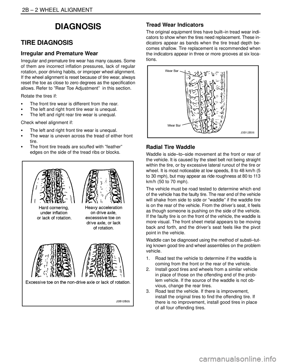
Irregular and Premature Wear
Irregular and premature tire wear has many causes. Some
of them are incorrect inflation pressures, lack of regular
rotation, poor driving habits, or improper wheel alignment.
If the wheel alignment is reset because of tire wear, always
reset the toe as close to zero degrees as the specification
allows. Refer to ”Rear Toe Adjustment” in this section.
Rotate the tires if:
S The front tire wear is different from the rear.
S The left and right front tire wear is unequal.
S The left and right rear tire wear is unequal.
Check wheel alignment if:
S The left and right front tire wear is unequal.
S The wear is uneven across the tread of either front
tire.
S The front tire treads are scuffed with ”feather”
edges on the side of the tread ribs or blocks.
Tread Wear Indicators
The original equipment tires have built–in tread wear indi-
cators to show when the tires need replacement. These in-
dicators appear as bands when the tire tread depth be-
comes shallow. Tire replacement is recommended when
the indicators appear in three or more grooves at six loca-
tions.
Radial Tire Waddle
Waddle is side–to–side movement at the front or rear of
the vehicle. It is caused by the steel belt not being straight
within the tire, or by excessive lateral runout of the tire or
wheel. It is most noticeable at low speeds, 8 to 48 km/h (5
to 30 mph), but may appear as ride roughness at 80 to 113
km/h (50 to 70 mph).
The vehicle must be road tested to determine which end
of the vehicle has the faulty tire. The rear end of the vehicle
will shake from side to side or ”waddle” if the waddle tire
is on the rear of the vehicle. From the driver’s seat, it feels
as though someone is pushing on the side of the vehicle.
If the faulty tire is on the front of the vehicle, the waddle is
more visual. The front sheet metal appears to be moving
back and forth, and the driver’s seat feels like the pivot
point in the vehicle.
Waddle can be diagnosed using the method of substi–tut-
ing known good tire and wheel assemblies on the problem
vehicle.
1. Road test the vehicle to determine if the waddle is
coming from the front or the rear of the vehicle.
2. Install good tires and wheels from a similar vehicle
in place of those on the offending end of the prob-
lem vehicle. If the source of the waddle is not ob-
vious, change the rear tires.
3. Road test the vehicle. If there is improvement,
install the original tires to find the offending tire. If
there is no improvement, install good tires in place
of all four offending tires.
Page 912 of 2643
WHEEL ALIGNMENT 2B – 5
DAEWOO V–121 BL4
VIBRATION DIAGNOSIS
Wheel imbalance causes most highway speed vibration
problems. A vibration can remain after dynamic balancing
because:
S A tire is out of round.
S A rim is out of round.
S A tire stiffness variation exists.
Measuring tire and wheel free runout will uncover only part
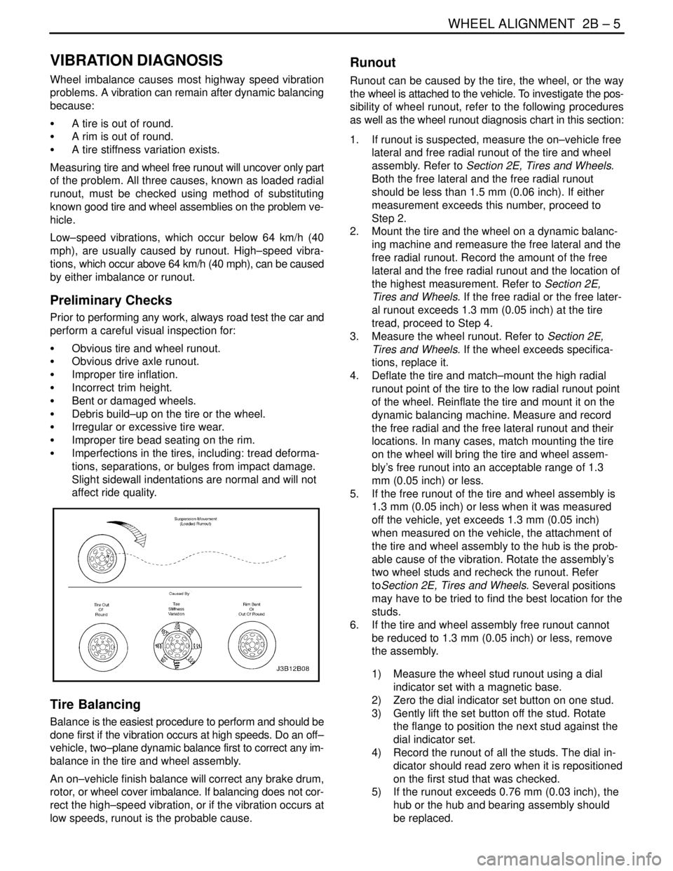
of the problem. All three causes, known as loaded radial
runout, must be checked using method of substituting
known good tire and wheel assemblies on the problem ve-
hicle.
Low–speed vibrations, which occur below 64 km/h (40
mph), are usually caused by runout. High–speed vibra-
tions, which occur above 64 km/h (40 mph), can be caused
by either imbalance or runout.
Preliminary Checks
Prior to performing any work, always road test the car and
perform a careful visual inspection for:
S Obvious tire and wheel runout.
S Obvious drive axle runout.
S Improper tire inflation.
S Incorrect trim height.
S Bent or damaged wheels.
S Debris build–up on the tire or the wheel.
S Irregular or excessive tire wear.
S Improper tire bead seating on the rim.
S Imperfections in the tires, including: tread deforma-
tions, separations, or bulges from impact damage.
Slight sidewall indentations are normal and will not
affect ride quality.
Tire Balancing
Balance is the easiest procedure to perform and should be
done first if the vibration occurs at high speeds. Do an off–
vehicle, two–plane dynamic balance first to correct any im-
balance in the tire and wheel assembly.
An on–vehicle finish balance will correct any brake drum,
rotor, or wheel cover imbalance. If balancing does not cor-
rect the high–speed vibration, or if the vibration occurs at
low speeds, runout is the probable cause.
Runout
Runout can be caused by the tire, the wheel, or the way
the wheel is attached to the vehicle. To investigate the pos-
sibility of wheel runout, refer to the following procedures
as well as the wheel runout diagnosis chart in this section:
1. If runout is suspected, measure the on–vehicle free
lateral and free radial runout of the tire and wheel
assembly. Refer to Section 2E, Tires and Wheels.
Both the free lateral and the free radial runout
should be less than 1.5 mm (0.06 inch). If either
measurement exceeds this number, proceed to
Step 2.
2. Mount the tire and the wheel on a dynamic balanc-
ing machine and remeasure the free lateral and the
free radial runout. Record the amount of the free
lateral and the free radial runout and the location of
the highest measurement. Refer to Section 2E,
Tires and Wheels. If the free radial or the free later-
al runout exceeds 1.3 mm (0.05 inch) at the tire
tread, proceed to Step 4.
3. Measure the wheel runout. Refer to Section 2E,
Tires and Wheels. If the wheel exceeds specifica-
tions, replace it.
4. Deflate the tire and match–mount the high radial
runout point of the tire to the low radial runout point
of the wheel. Reinflate the tire and mount it on the
dynamic balancing machine. Measure and record
the free radial and the free lateral runout and their
locations. In many cases, match mounting the tire
on the wheel will bring the tire and wheel assem-
bly’s free runout into an acceptable range of 1.3
mm (0.05 inch) or less.
5. If the free runout of the tire and wheel assembly is
1.3 mm (0.05 inch) or less when it was measured
off the vehicle, yet exceeds 1.3 mm (0.05 inch)
when measured on the vehicle, the attachment of
the tire and wheel assembly to the hub is the prob-
able cause of the vibration. Rotate the assembly’s
two wheel studs and recheck the runout. Refer
toSection 2E, Tires and Wheels. Several positions
may have to be tried to find the best location for the
studs.
6. If the tire and wheel assembly free runout cannot
be reduced to 1.3 mm (0.05 inch) or less, remove
the assembly.
1) Measure the wheel stud runout using a dial
indicator set with a magnetic base.
2) Zero the dial indicator set button on one stud.
3) Gently lift the set button off the stud. Rotate
the flange to position the next stud against the
dial indicator set.
4) Record the runout of all the studs. The dial in-
dicator should read zero when it is repositioned
on the first stud that was checked.
5) If the runout exceeds 0.76 mm (0.03 inch), the
hub or the hub and bearing assembly should
be replaced.
Page 925 of 2643

2C – 8IFRONT SUSPENSION
DAEWOO V–121 BL4
1. Cap
2. Strut Upper Nut
3. Piston Rod Nut
4. Strut Mount
5. Strut Bearing
6. Washer
7. Upper Spring Seat
8. Front Spring Locator
9. Upper Spring Insulator
10. Hollow Bumper
11. Front Coil Spring
12. Lower Spring Insulator
13. Front Strut
14. Steering Knuckle–to–Strut Assembly
15. Nut
16. Steering Knuckle
17. Brake Shield
18. Front Hub Bearing19. Outer Snap Ring
20. Front Hub
21. Front Brake Disc
22. Washer
23. Caulking Nut
24. Stabilizer Clamp Bolt
25. Stabilizer Clamp
26. Stabilizer Clamp Insulator
27. Stabilizer
28. Stabilizer Link Nut
29. Stabilizer Link
30. Front Suspension Crossmember
31. Crossmember Cover
32. Crossmember Cover Bolt
33. Crossmember Bolt
34. Crossmember Nut
35. Control Arm
36. Ball Joint
Page 939 of 2643
2C – 22IFRONT SUSPENSION
DAEWOO V–121 BL4
Assembly Procedure
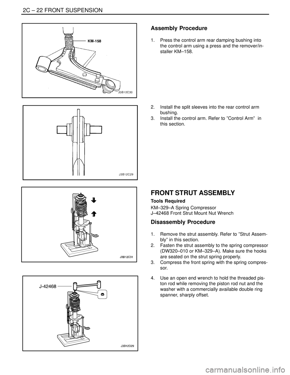
1. Press the control arm rear damping bushing into
the control arm using a press and the remover/in-
staller KM–158.
2. Install the split sleeves into the rear control arm
bushing.
3. Install the control arm. Refer to ”Control Arm” in
this section.
FRONT STRUT ASSEMBLY
Tools Required
KM–329–A Spring Compressor
J–42468 Front Strut Mount Nut Wrench
Disassembly Procedure
1. Remove the strut assembly. Refer to ”Strut Assem-
bly” in this section.
2. Fasten the strut assembly to the spring compressor
(DW320–010 or KM–329–A). Make sure the hooks
are seated on the strut spring properly.
3. Compress the front spring with the spring compres-
sor.
4. Use an open end wrench to hold the threaded pis-
ton rod while removing the piston rod nut and the
washer with a commercially available double ring
spanner, sharply offset.