2004 DAEWOO LACETTI seat
[x] Cancel search: seatPage 180 of 2643
1C2 – 60I1.8L DOHC ENGINE MECHANICAL
DAEWOO V–121 BL4
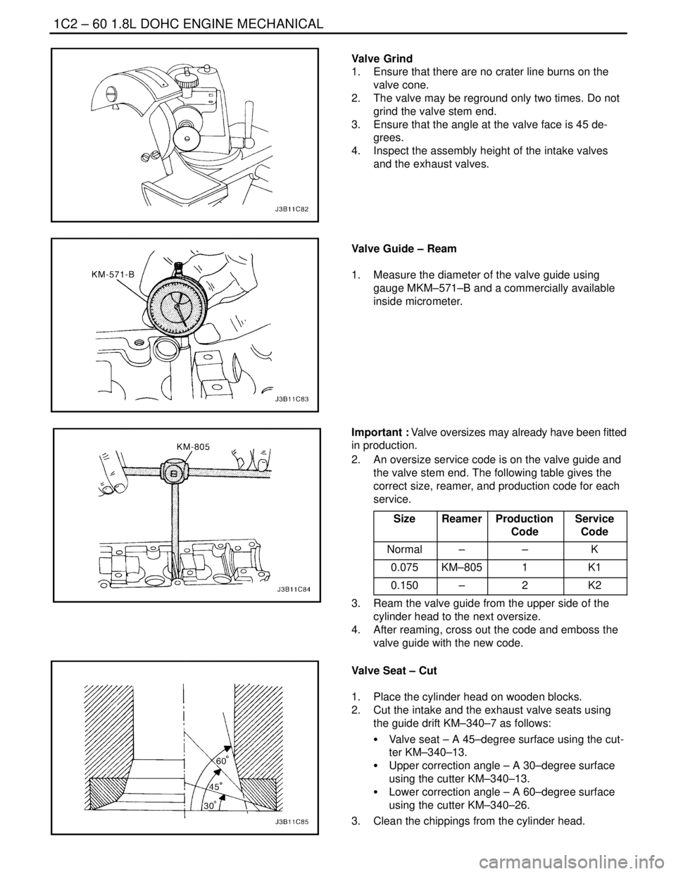
Valve Grind
1. Ensure that there are no crater line burns on the
valve cone.
2. The valve may be reground only two times. Do not
grind the valve stem end.
3. Ensure that the angle at the valve face is 45 de-
grees.
4. Inspect the assembly height of the intake valves
and the exhaust valves.
Valve Guide – Ream
1. Measure the diameter of the valve guide using
gauge MKM–571–B and a commercially available
inside micrometer.
Important : Valve oversizes may already have been fitted
in production.
2. An oversize service code is on the valve guide and
the valve stem end. The following table gives the
correct size, reamer, and production code for each
service.
Size
ReamerProduction
CodeService
Code
Normal––K
0.075KM–8051K1
0.150–2K2
3. Ream the valve guide from the upper side of the
cylinder head to the next oversize.
4. After reaming, cross out the code and emboss the
valve guide with the new code.
Valve Seat – Cut
1. Place the cylinder head on wooden blocks.
2. Cut the intake and the exhaust valve seats using
the guide drift KM–340–7 as follows:
S Valve seat – A 45–degree surface using the cut-
ter KM–340–13.
S Upper correction angle – A 30–degree surface
using the cutter KM–340–13.
S Lower correction angle – A 60–degree surface
using the cutter KM–340–26.
3. Clean the chippings from the cylinder head.
Page 181 of 2643
1.8L DOHC ENGINE MECHANICAL 1C2 – 61
DAEWOO V–121 BL4
4. Inspect the dimension for the valve seat width.
S Intake: 1.2 to 1.4 mm (0.047 to 0.055 inch).
S Exhaust: 1.4 to 1.8 mm (0.055 to 0.070 inch).
5. Inspect the assembly height of the intake valves
and the exhaust valves. If the dimension is exceed-
ed, install new valves. Inspect the assembly height
of the intake valves and the exhaust valves again. If
the valve assembly height is still too large despite
replacing the valves, replace the cylinder head.
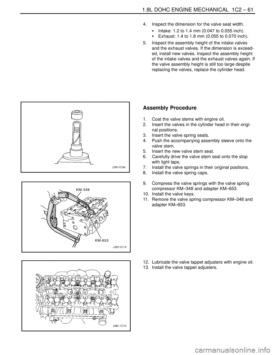
Assembly Procedure
1. Coat the valve stems with engine oil.
2. Insert the valves in the cylinder head in their origi-
nal positions.
3. Insert the valve spring seats.
4. Push the accompanying assembly sleeve onto the
valve stem.
5. Insert the new valve stem seat.
6. Carefully drive the valve stem seal onto the stop
with light taps.
7. Install the valve springs in their original positions.
8. Install the valve spring caps.
9. Compress the valve springs with the valve spring
compressor KM–348 and adapter KM–653.
10. Install the valve keys.
11. Remove the valve spring compressor KM–348 and
adapter KM–653.
12. Lubricate the valve tappet adjusters with engine oil.
13. Install the valve tappet adjusters.
Page 198 of 2643
ENGINE COOLING 1D – 3
DAEWOO V–121 BL4
DIAGNOSIS
THERMOSTAT TEST
1. Remove the thermostat from the vehicle. Refer to
”Thermostat” in this section.
2. Make sure the valve spring is tight when the ther-
mostat is fully closed. If the spring is not tight, re-
place the thermostat.
3. Suspend the thermostat and a thermometer in a
pan of 50/50 mixture of ethylene glycol and water.
Do not let the thermostat or the thermometer rest
on the bottom of the pan because the uneven con-
centration of heat on the bottom could result in in-
accurate temperature measurements.
4. Heat the pan on a burner.
5. Use the thermometer to measure the temperature
of the heated solution.
6. The thermostat should begin to open at 87°C
(189°F) and it should be fully open at 102°C
(216°F). If it does not open at these temperatures,
replace the thermostat.
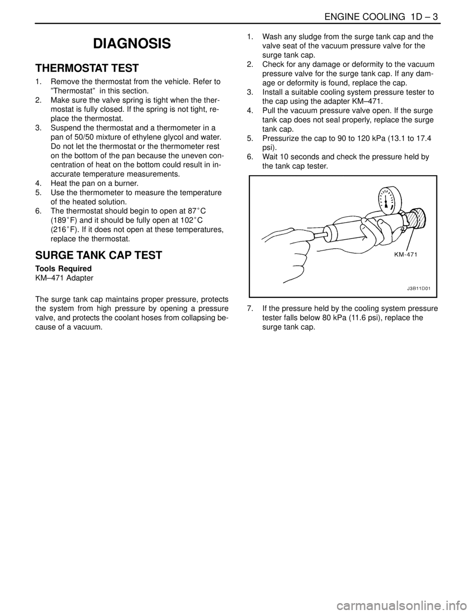
SURGE TANK CAP TEST
Tools Required
KM–471 Adapter
The surge tank cap maintains proper pressure, protects
the system from high pressure by opening a pressure
valve, and protects the coolant hoses from collapsing be-
cause of a vacuum.1. Wash any sludge from the surge tank cap and the
valve seat of the vacuum pressure valve for the
surge tank cap.
2. Check for any damage or deformity to the vacuum
pressure valve for the surge tank cap. If any dam-
age or deformity is found, replace the cap.
3. Install a suitable cooling system pressure tester to
the cap using the adapter KM–471.
4. Pull the vacuum pressure valve open. If the surge
tank cap does not seal properly, replace the surge
tank cap.
5. Pressurize the cap to 90 to 120 kPa (13.1 to 17.4
psi).
6. Wait 10 seconds and check the pressure held by
the tank cap tester.
7. If the pressure held by the cooling system pressure
tester falls below 80 kPa (11.6 psi), replace the
surge tank cap.
Page 199 of 2643

1D – 4IENGINE COOLING
DAEWOO V–121 BL4
COOLING SYSTEM DIAGNOSIS
Engine Overheats
ChecksAction
Check for a loss of the coolant.Add the coolant.
Check for a weak coolant solution.Confirm that the coolant solution is a 50/50 mixture of eth-
ylene glycol and water.
Check the front of the radiator for any dirt, any leaves, or
any insects.Clean the front of the radiator.
Check for leakage from the hoses, the coolant pump, the
heater, the thermostat housing, the radiator, the core
plugs, or the head gasket.Replace any damaged components.
Check for a faulty thermostat.Replace a damaged thermostat.
Check for retarded ignition timing.Perform an ECM code diagnosis. Confirm the integrity of
the timing belt.
Check for an improperly operating electric cooling fan.Replace the electric cooling fan.
Check for radiator hoses that are plugged or rotted.Replace any damaged radiator hoses.
Check for a faulty water pump.Replace a faulty water pump.
Check for a faulty surge tank cap.Replace a faulty surge tank cap.
Check for a cylinder head or an engine block that is
cracked or plugged.Repair the damaged cylinder head or the damaged engine
block.
Loss of Coolant
ChecksAction
Check for a leak in the radiator.Replace a damaged radiator.
Check for a leak in the following locations:
S Surge tank.
S Hose.Replace the following parts, as needed:
S Surge tank.
S Hose.
Check for loose or damaged radiator hoses, heater hoses,
and connections.Reseat the hoses.
Replace the hoses or the clamps.
Check for leaks in the coolant pump seal.Replace the coolant pump seal.
Check for leaks in the coolant pump gasket.Replace the coolant pump gasket.
Check for an improper cylinder head torque.Tighten the cylinder head bolts to specifications.
Replace the cylinder head gasket, if needed.
Check for leaks in the following locations:
S Intake manifold.
S Cylinder head gasket.
S Cylinder block plug.
S Heater core.
S Radiator drain plug.Repair or replace any components, as needed, to correct
the leak.
Engine Fails to Reach Normal Operating Temperature or Cool Air
from the Heater
ChecksAction
Check to determine if the thermostat is stuck open or is the
wrong type of thermostat.Install a new thermostat of the correct type and heat range.
Check the coolant level to determine if it is below the MIN
mark on the surge tank.Add sufficient coolant to raise the fluid to the specified
mark on the surge tank.
Page 204 of 2643
ENGINE COOLING 1D – 9
DAEWOO V–121 BL4
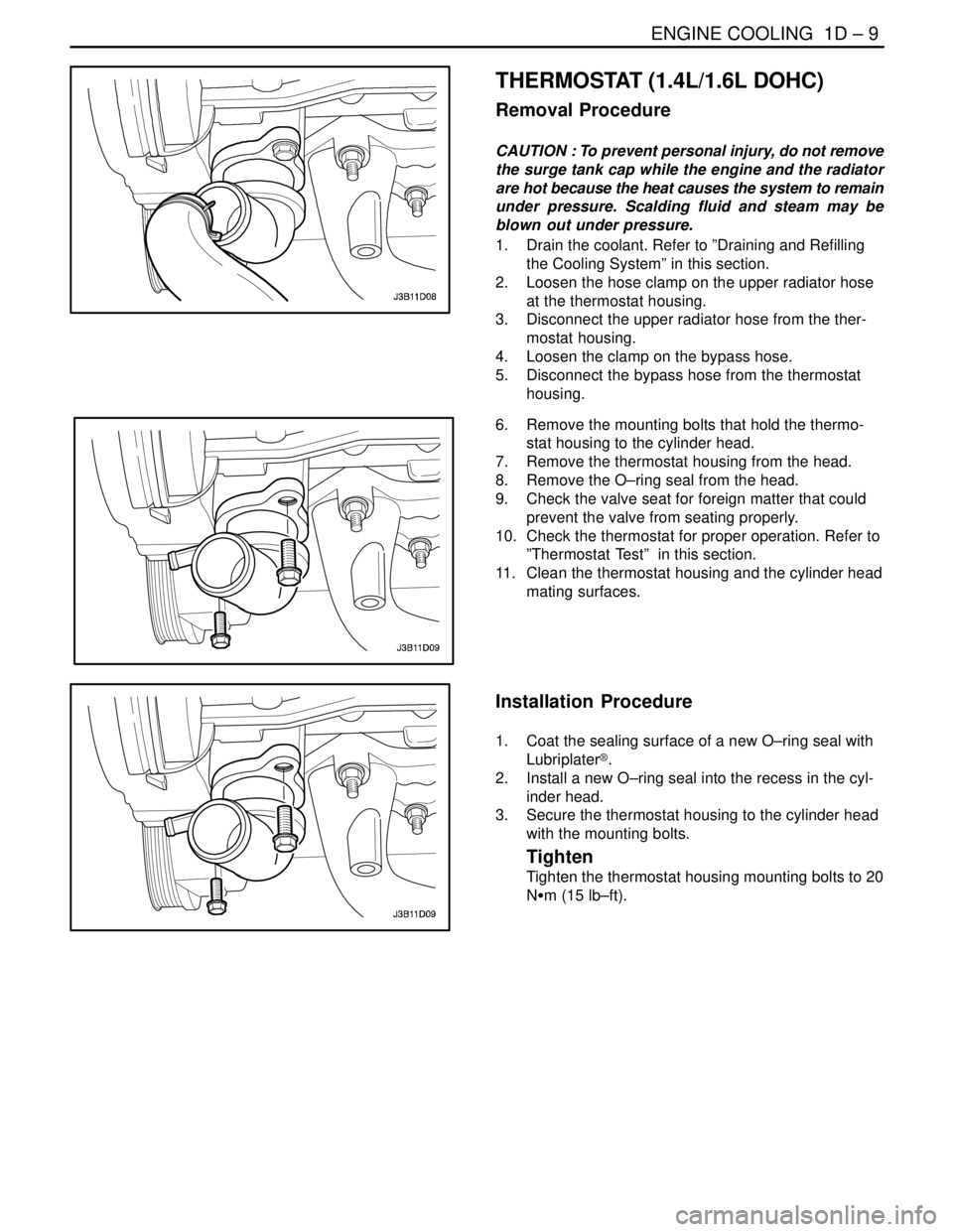
THERMOSTAT (1.4L/1.6L DOHC)
Removal Procedure
CAUTION : To prevent personal injury, do not remove
the surge tank cap while the engine and the radiator
are hot because the heat causes the system to remain
under pressure. Scalding fluid and steam may be
blown out under pressure.
1. Drain the coolant. Refer to ”Draining and Refilling
the Cooling System” in this section.
2. Loosen the hose clamp on the upper radiator hose
at the thermostat housing.
3. Disconnect the upper radiator hose from the ther-
mostat housing.
4. Loosen the clamp on the bypass hose.
5. Disconnect the bypass hose from the thermostat
housing.
6. Remove the mounting bolts that hold the thermo-
stat housing to the cylinder head.
7. Remove the thermostat housing from the head.
8. Remove the O–ring seal from the head.
9. Check the valve seat for foreign matter that could
prevent the valve from seating properly.
10. Check the thermostat for proper operation. Refer to
”Thermostat Test” in this section.
11. Clean the thermostat housing and the cylinder head
mating surfaces.
Installation Procedure
1. Coat the sealing surface of a new O–ring seal with
Lubriplater®.
2. Install a new O–ring seal into the recess in the cyl-
inder head.
3. Secure the thermostat housing to the cylinder head
with the mounting bolts.
Tighten
Tighten the thermostat housing mounting bolts to 20
NSm (15 lb–ft).
Page 205 of 2643
1D – 10IENGINE COOLING
DAEWOO V–121 BL4
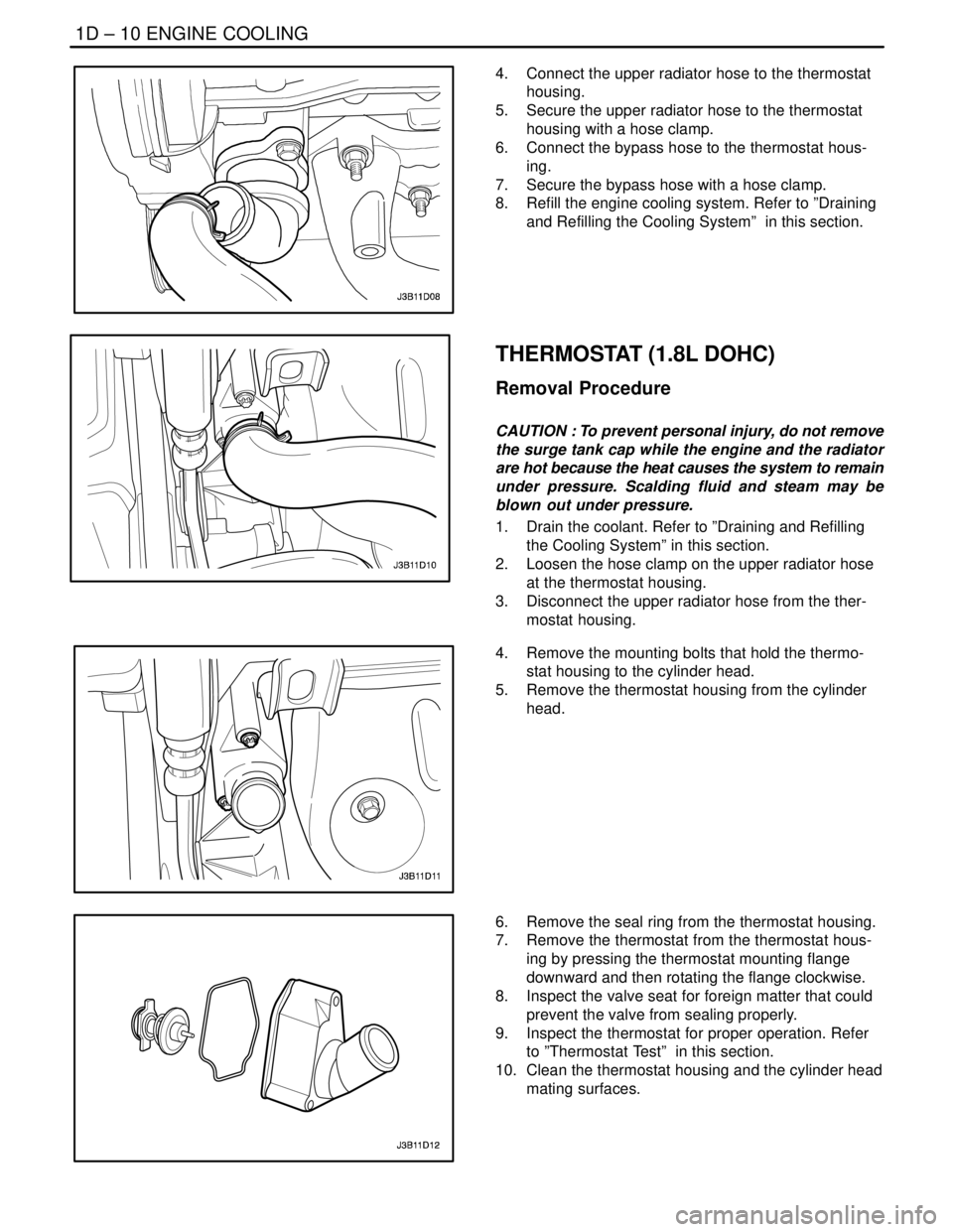
4. Connect the upper radiator hose to the thermostat
housing.
5. Secure the upper radiator hose to the thermostat
housing with a hose clamp.
6. Connect the bypass hose to the thermostat hous-
ing.
7. Secure the bypass hose with a hose clamp.
8. Refill the engine cooling system. Refer to ”Draining
and Refilling the Cooling System” in this section.
THERMOSTAT (1.8L DOHC)
Removal Procedure
CAUTION : To prevent personal injury, do not remove
the surge tank cap while the engine and the radiator
are hot because the heat causes the system to remain
under pressure. Scalding fluid and steam may be
blown out under pressure.
1. Drain the coolant. Refer to ”Draining and Refilling
the Cooling System” in this section.
2. Loosen the hose clamp on the upper radiator hose
at the thermostat housing.
3. Disconnect the upper radiator hose from the ther-
mostat housing.
4. Remove the mounting bolts that hold the thermo-
stat housing to the cylinder head.
5. Remove the thermostat housing from the cylinder
head.
6. Remove the seal ring from the thermostat housing.
7. Remove the thermostat from the thermostat hous-
ing by pressing the thermostat mounting flange
downward and then rotating the flange clockwise.
8. Inspect the valve seat for foreign matter that could
prevent the valve from sealing properly.
9. Inspect the thermostat for proper operation. Refer
to ”Thermostat Test” in this section.
10. Clean the thermostat housing and the cylinder head
mating surfaces.
Page 206 of 2643
ENGINE COOLING 1D – 11
DAEWOO V–121 BL4
Installation Procedure
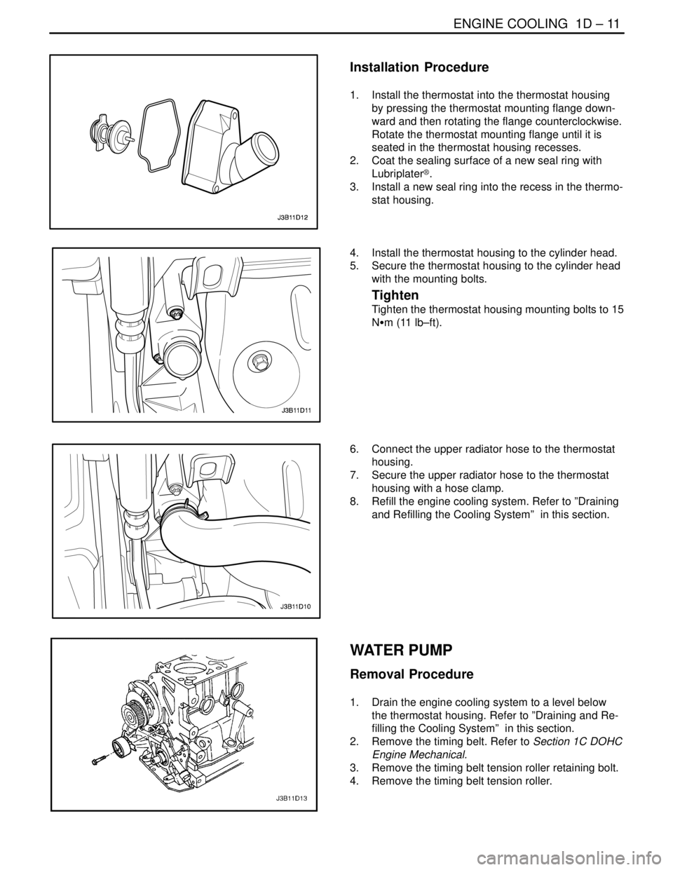
1. Install the thermostat into the thermostat housing
by pressing the thermostat mounting flange down-
ward and then rotating the flange counterclockwise.
Rotate the thermostat mounting flange until it is
seated in the thermostat housing recesses.
2. Coat the sealing surface of a new seal ring with
Lubriplater®.
3. Install a new seal ring into the recess in the thermo-
stat housing.
4. Install the thermostat housing to the cylinder head.
5. Secure the thermostat housing to the cylinder head
with the mounting bolts.
Tighten
Tighten the thermostat housing mounting bolts to 15
NSm (11 lb–ft).
6. Connect the upper radiator hose to the thermostat
housing.
7. Secure the upper radiator hose to the thermostat
housing with a hose clamp.
8. Refill the engine cooling system. Refer to ”Draining
and Refilling the Cooling System” in this section.
WATER PUMP
Removal Procedure
1. Drain the engine cooling system to a level below
the thermostat housing. Refer to ”Draining and Re-
filling the Cooling System” in this section.
2. Remove the timing belt. Refer to Section 1C DOHC
Engine Mechanical.
3. Remove the timing belt tension roller retaining bolt.
4. Remove the timing belt tension roller.
Page 209 of 2643
1D – 14IENGINE COOLING
DAEWOO V–121 BL4
Tighten
Tighten the fan motor retaining screws to 4 NSm (35
lb–in).
3. Turn over the fan shroud assembly.
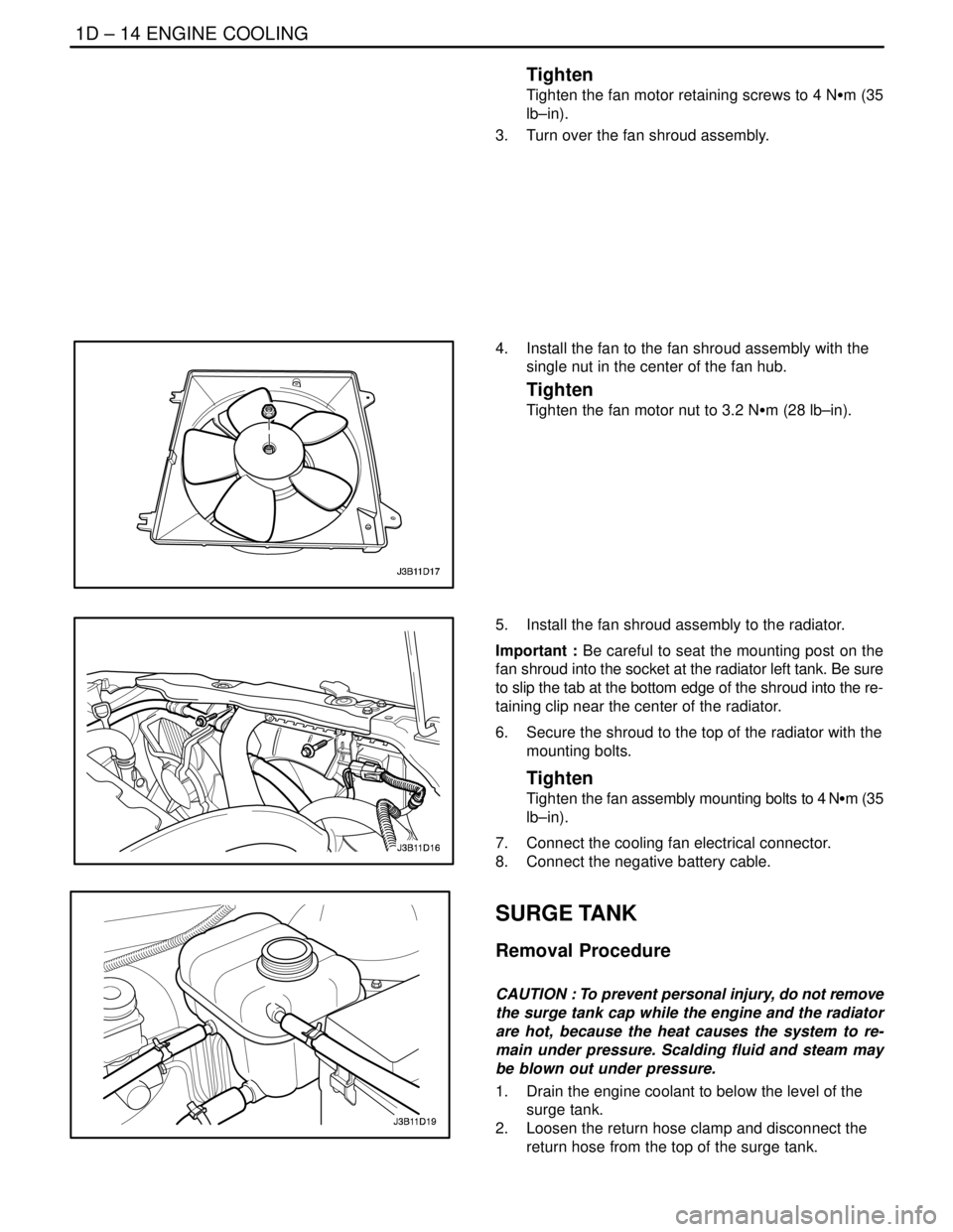
4. Install the fan to the fan shroud assembly with the
single nut in the center of the fan hub.
Tighten
Tighten the fan motor nut to 3.2 NSm (28 lb–in).
5. Install the fan shroud assembly to the radiator.
Important : Be careful to seat the mounting post on the
fan shroud into the socket at the radiator left tank. Be sure
to slip the tab at the bottom edge of the shroud into the re-
taining clip near the center of the radiator.
6. Secure the shroud to the top of the radiator with the
mounting bolts.
Tighten
Tighten the fan assembly mounting bolts to 4 NSm (35
lb–in).
7. Connect the cooling fan electrical connector.
8. Connect the negative battery cable.
SURGE TANK
Removal Procedure
CAUTION : To prevent personal injury, do not remove
the surge tank cap while the engine and the radiator
are hot, because the heat causes the system to re-
main under pressure. Scalding fluid and steam may
be blown out under pressure.
1. Drain the engine coolant to below the level of the
surge tank.
2. Loosen the return hose clamp and disconnect the
return hose from the top of the surge tank.