Page 104 of 2643
1.4L/1.6L DOHC ENGINE MECHANICAL 1C1 – 61
DAEWOO V–121 BL4
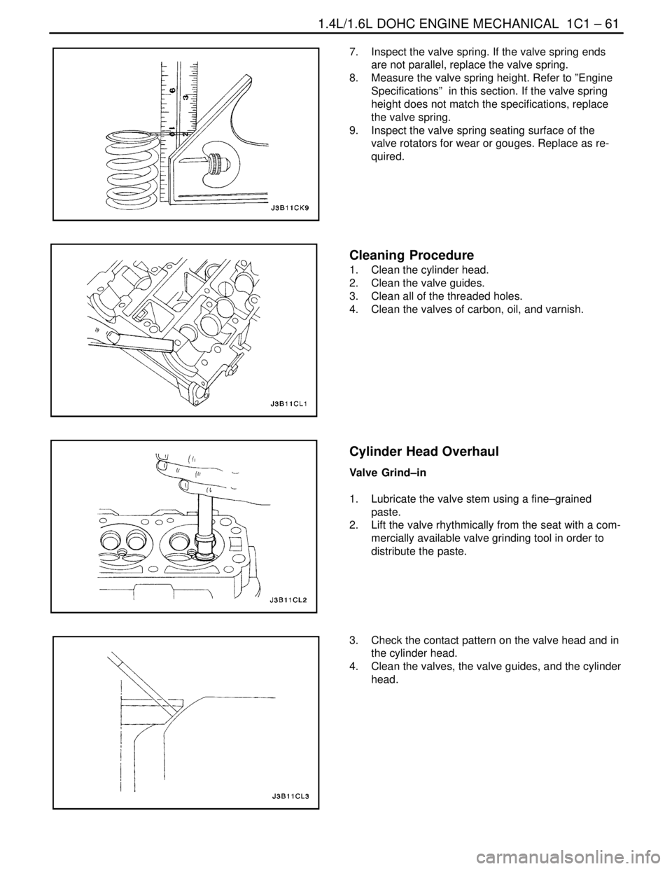
7. Inspect the valve spring. If the valve spring ends
are not parallel, replace the valve spring.
8. Measure the valve spring height. Refer to ”Engine
Specifications” in this section. If the valve spring
height does not match the specifications, replace
the valve spring.
9. Inspect the valve spring seating surface of the
valve rotators for wear or gouges. Replace as re-
quired.
Cleaning Procedure
1. Clean the cylinder head.
2. Clean the valve guides.
3. Clean all of the threaded holes.
4. Clean the valves of carbon, oil, and varnish.
Cylinder Head Overhaul
Valve Grind–in
1. Lubricate the valve stem using a fine–grained
paste.
2. Lift the valve rhythmically from the seat with a com-
mercially available valve grinding tool in order to
distribute the paste.
3. Check the contact pattern on the valve head and in
the cylinder head.
4. Clean the valves, the valve guides, and the cylinder
head.
Page 105 of 2643
1C1 – 62I1.4L/1.6L DOHC ENGINE MECHANICAL
DAEWOO V–121 BL4
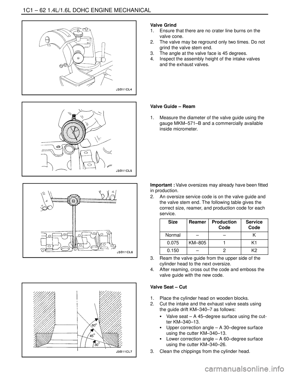
Valve Grind
1. Ensure that there are no crater line burns on the
valve cone.
2. The valve may be reground only two times. Do not
grind the valve stem end.
3. The angle at the valve face is 45 degrees.
4. Inspect the assembly height of the intake valves
and the exhaust valves.
Valve Guide – Ream
1. Measure the diameter of the valve guide using the
gauge MKM–571–B and a commercially available
inside micrometer.
Important : Valve oversizes may already have been fitted
in production.
2. An oversize service code is on the valve guide and
the valve stem end. The following table gives the
correct size, reamer, and production code for each
service.
Size
ReamerProduction
CodeService
Code
Normal––K
0.075KM–8051K1
0.150–2K2
3. Ream the valve guide from the upper side of the
cylinder head to the next oversize.
4. After reaming, cross out the code and emboss the
valve guide with the new code.
Valve Seat – Cut
1. Place the cylinder head on wooden blocks.
2. Cut the intake and the exhaust valve seats using
the guide drift KM–340–7 as follows:
S Valve seat – A 45–degree surface using the cut-
ter KM–340–13.
S Upper correction angle – A 30–degree surface
using the cutter KM–340–13.
S Lower correction angle – A 60–degree surface
using the cutter KM–340–26.
3. Clean the chippings from the cylinder head.
Page 106 of 2643
1.4L/1.6L DOHC ENGINE MECHANICAL 1C1 – 63
DAEWOO V–121 BL4
4. Inspect the dimension for the valve seat width.
S Intake: 1.17 to 1.57 mm (0.046 to 0.062 inch).
S Exhaust: 1.4 to 1.8 mm (0.055 to 0.071 inch).
5. Inspect the assembly height of the intake valves
and the exhaust valves. If the dimension is exceed-
ed, install new valves. Inspect the assembly height
of the intake valves and the exhaust valves again. If
the valve assembly height is still too large despite
replacing the valves, replace the cylinder head.
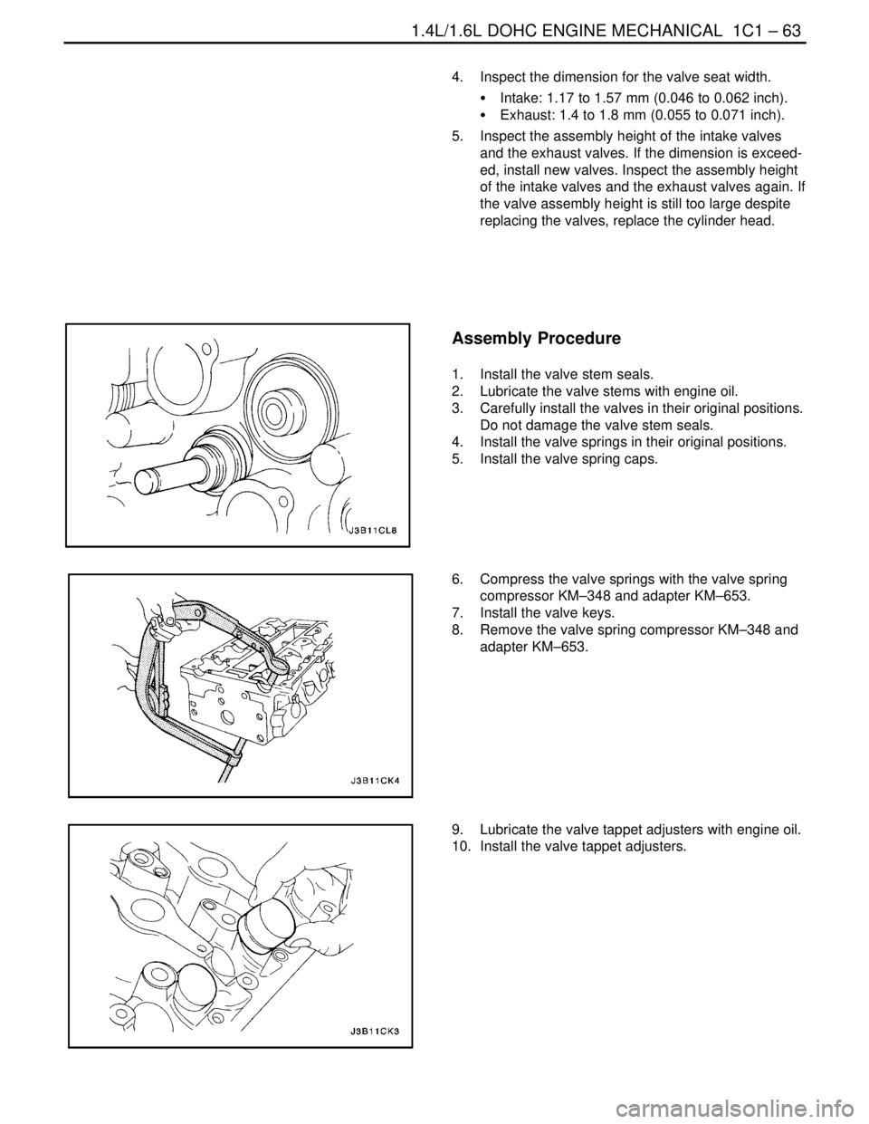
Assembly Procedure
1. Install the valve stem seals.
2. Lubricate the valve stems with engine oil.
3. Carefully install the valves in their original positions.
Do not damage the valve stem seals.
4. Install the valve springs in their original positions.
5. Install the valve spring caps.
6. Compress the valve springs with the valve spring
compressor KM–348 and adapter KM–653.
7. Install the valve keys.
8. Remove the valve spring compressor KM–348 and
adapter KM–653.
9. Lubricate the valve tappet adjusters with engine oil.
10. Install the valve tappet adjusters.
Page 123 of 2643

1.8L DOHC ENGINE MECHANICAL 1C2 – 3
DAEWOO V–121 BL4
Application Description
Diameter (All)
Out of Round (Maximum)48.970~ 48.988 mm (1.9279~1.9287 in.)
0.004 mm (0.00015 in.)
Cylinder Head:
Valve Stem Protrusion39.2~39.8 mm (1.54~1.56 in.)
Valve Guide Height13.7~14.0 mm (0.54~0.57 in.)
Overall Height134 ± 0.025 mm (5.2755~0.0009 in.)
Minimum Overall Height After Machining133.9 mm (5.27 in.)
Valve System:
Valve Lash CompensatorsHydraulic Tappet
Seat Runout (Maximum, All)0.03 mm (0.00118 in.)
Face Runout (Maximum, All)0.03 mm (0.00118 in.)
Valve Stem Diameter:
Intake
Exhaust5.945~5.960 mm (0.2341~0.2346 in.)
5.945~5.960 mm (0.2341~0.2346 in.)
Valve Diameter:
Intake
Exhaust32 ± 0.1 mm (1.2598 ± 0.0039 in.)
29 ± 0.1 mm (1.1417 ± 0.0039 in.)
Valve Seat Width:
Intake
Exhaust1.0~1.5 mm (0.039~0.059 in.)
1.7~2.2 mm (0.066~0.086 in.)
Valve Face Angle44°
Valve Guide Inside Diameter7.03~7.05 mm (0.276~0.277 in.)
Oil Pump:
Gear Lash0.10~0.20 mm (0.003~0.007 in.)
Outer Gear to Body0.11~0.19 mm (0.004~0.007 in.)
Outer Gear to Crescent0.40~0.50 mm (0.015~0.019 in.)
Inner Gear to Crescent0.35~0.40 mm (0.013~0.015 in.)
End Clearance0.030~0.10 mm (0.001~0.003 in.)
Sealants and Adhesives:
Rear Main Bearing CapGE p/n RTV 159
Camshaft Carrier to Cylinder HeadHN 1581 (Loctite® 515)
Oil Pan BoltsHN 1256 (Loctite® 242)
Oil Pump BoltsHN 1256 (Loctite® 242)
Oil Pan Pickup Tube BoltsHN 1256 (Loctite® 242)
Oil Gallery PlugHN 1256 (Loctite® 242)
Coolant Jacket Caps and Plugs (Freeze Plugs)HN 1756 (Loctite® 176)
Exhaust Manifold Studs/NutsAnti–seize Compound (HMC Spec HN1325)
Page 129 of 2643

1.8L DOHC ENGINE MECHANICAL 1C2 – 9
DAEWOO V–121 BL4
1. Bolt
2. Spark Plug Cover
3. Oil Filler Cap
4. Oil Filler Cap Seal
5. Bolt
6. Camshaft Cover
7. Camshaft Cover Gasket
8. Tappet Adjuster
9. Valve Key
10. Valve Spring Cap
11. Valve Spring
12. Valve Stem Seal
13. Valve Spring Seat
14. Valve Guide
15. Intake Valve Seat Ring
16. Exhaust Valve Seat Ring
17. Intake Valve
18. Exhaust Valve
19. Bolt
20. Front Camshaft Cap
21. Head Bolt
22. Bolt
23. Intermediate Camshaft Cap
24. Exhaust Gas Recirculation Adapter
25. Exhaust Gas Recirculation Adapter Gasket
26. Cylinder Head
27. Exhaust Manifold Gasket28. Exhaust Manifold
29. Nut
30. Exhaust Manifold Heat Shield
31. Cylinder Head Gasket
32. Bolt
33. Thermostat Housing
34. Thermostat Housing Gasket
35. Stud
36. Sleeve
37. Plug
38. Bolt
39. Camshaft Position Sensor
40. Oil Gallery Plug
41. Exhaust Camshaft
42. Seal Ring
43. Camshaft Gear
44. Washer
45. Camshaft Gear Bolt
46. Intake Camshaft
47. Intake Manifold Gasket
48. Intake Manifold
49. Throttle Body Gasket
50. Throttle Body
51. Nut
52. Charcoal Canister Purge Solenoid
53. Exhaust Gas Recirculation Solenoid
Page 143 of 2643
1.8L DOHC ENGINE MECHANICAL 1C2 – 23
DAEWOO V–121 BL4
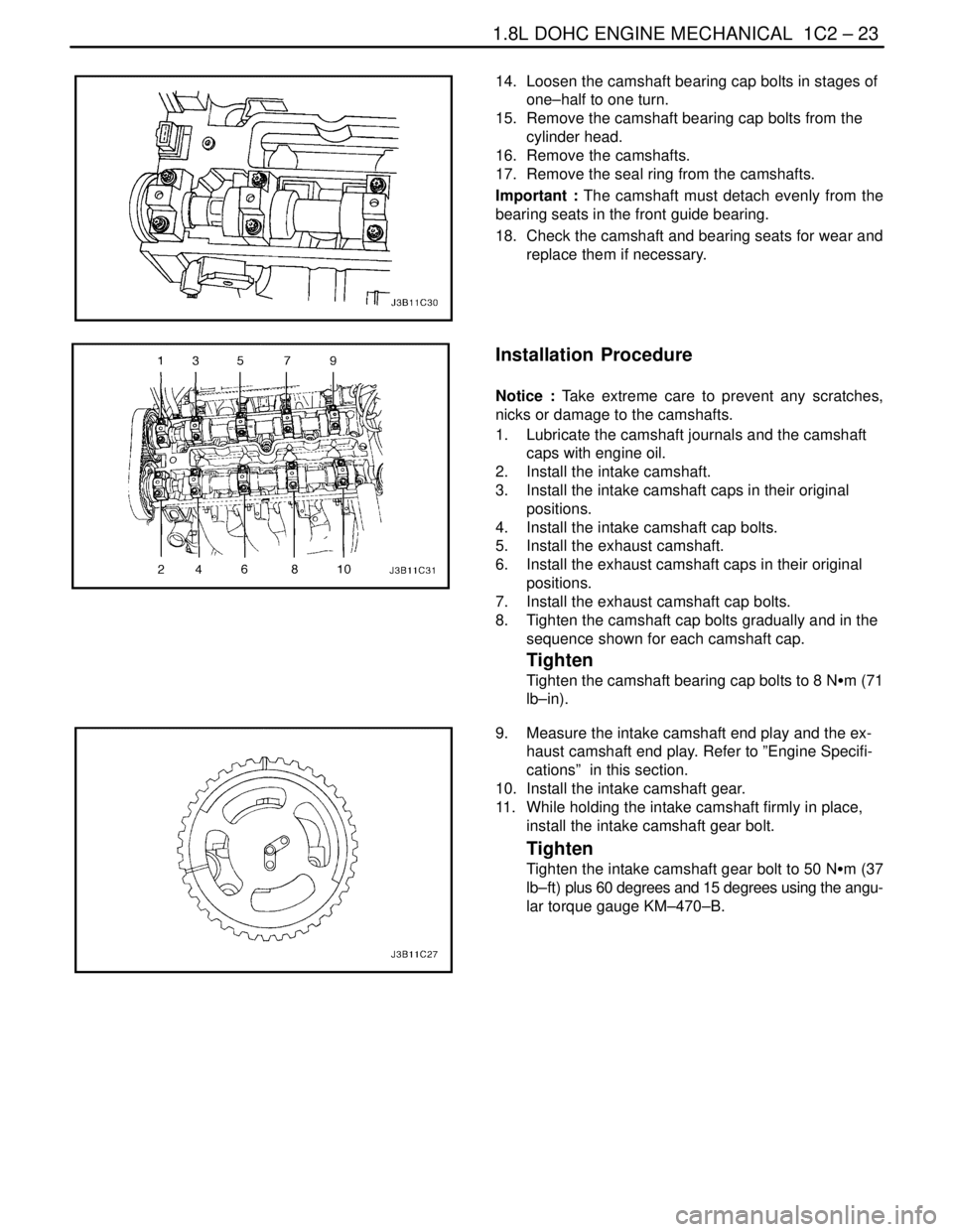
14. Loosen the camshaft bearing cap bolts in stages of
one–half to one turn.
15. Remove the camshaft bearing cap bolts from the
cylinder head.
16. Remove the camshafts.
17. Remove the seal ring from the camshafts.
Important : The camshaft must detach evenly from the
bearing seats in the front guide bearing.
18. Check the camshaft and bearing seats for wear and
replace them if necessary.
Installation Procedure
Notice : Take extreme care to prevent any scratches,
nicks or damage to the camshafts.
1. Lubricate the camshaft journals and the camshaft
caps with engine oil.
2. Install the intake camshaft.
3. Install the intake camshaft caps in their original
positions.
4. Install the intake camshaft cap bolts.
5. Install the exhaust camshaft.
6. Install the exhaust camshaft caps in their original
positions.
7. Install the exhaust camshaft cap bolts.
8. Tighten the camshaft cap bolts gradually and in the
sequence shown for each camshaft cap.
Tighten
Tighten the camshaft bearing cap bolts to 8 NSm (71
lb–in).
9. Measure the intake camshaft end play and the ex-
haust camshaft end play. Refer to ”Engine Specifi-
cations” in this section.
10. Install the intake camshaft gear.
11. While holding the intake camshaft firmly in place,
install the intake camshaft gear bolt.
Tighten
Tighten the intake camshaft gear bolt to 50 NSm (37
lb–ft) plus 60 degrees and 15 degrees using the angu-
lar torque gauge KM–470–B.
Page 178 of 2643
1C2 – 58I1.8L DOHC ENGINE MECHANICAL
DAEWOO V–121 BL4
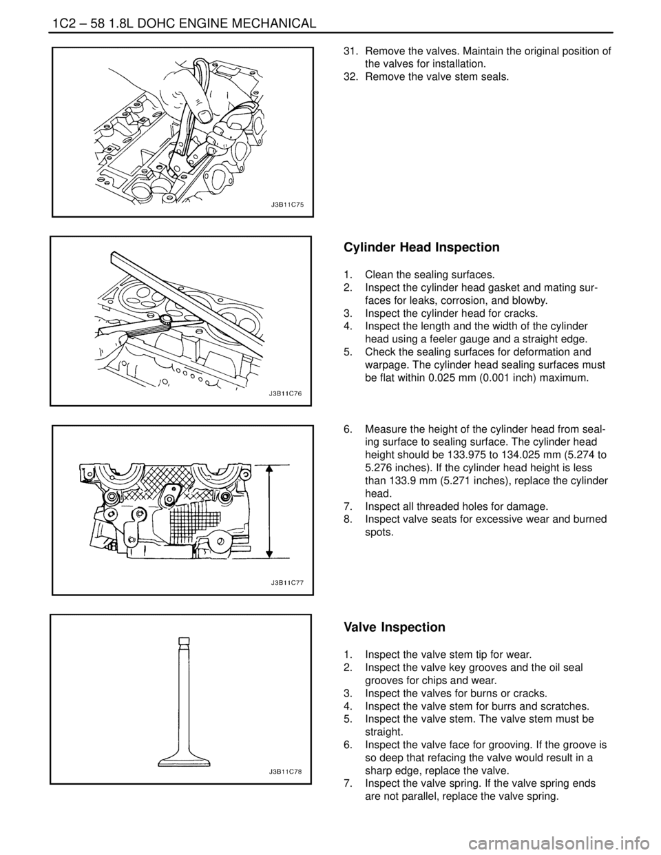
31. Remove the valves. Maintain the original position of
the valves for installation.
32. Remove the valve stem seals.
Cylinder Head Inspection
1. Clean the sealing surfaces.
2. Inspect the cylinder head gasket and mating sur-
faces for leaks, corrosion, and blowby.
3. Inspect the cylinder head for cracks.
4. Inspect the length and the width of the cylinder
head using a feeler gauge and a straight edge.
5. Check the sealing surfaces for deformation and
warpage. The cylinder head sealing surfaces must
be flat within 0.025 mm (0.001 inch) maximum.
6. Measure the height of the cylinder head from seal-
ing surface to sealing surface. The cylinder head
height should be 133.975 to 134.025 mm (5.274 to
5.276 inches). If the cylinder head height is less
than 133.9 mm (5.271 inches), replace the cylinder
head.
7. Inspect all threaded holes for damage.
8. Inspect valve seats for excessive wear and burned
spots.
Valve Inspection
1. Inspect the valve stem tip for wear.
2. Inspect the valve key grooves and the oil seal
grooves for chips and wear.
3. Inspect the valves for burns or cracks.
4. Inspect the valve stem for burrs and scratches.
5. Inspect the valve stem. The valve stem must be
straight.
6. Inspect the valve face for grooving. If the groove is
so deep that refacing the valve would result in a
sharp edge, replace the valve.
7. Inspect the valve spring. If the valve spring ends
are not parallel, replace the valve spring.
Page 179 of 2643
1.8L DOHC ENGINE MECHANICAL 1C2 – 59
DAEWOO V–121 BL4
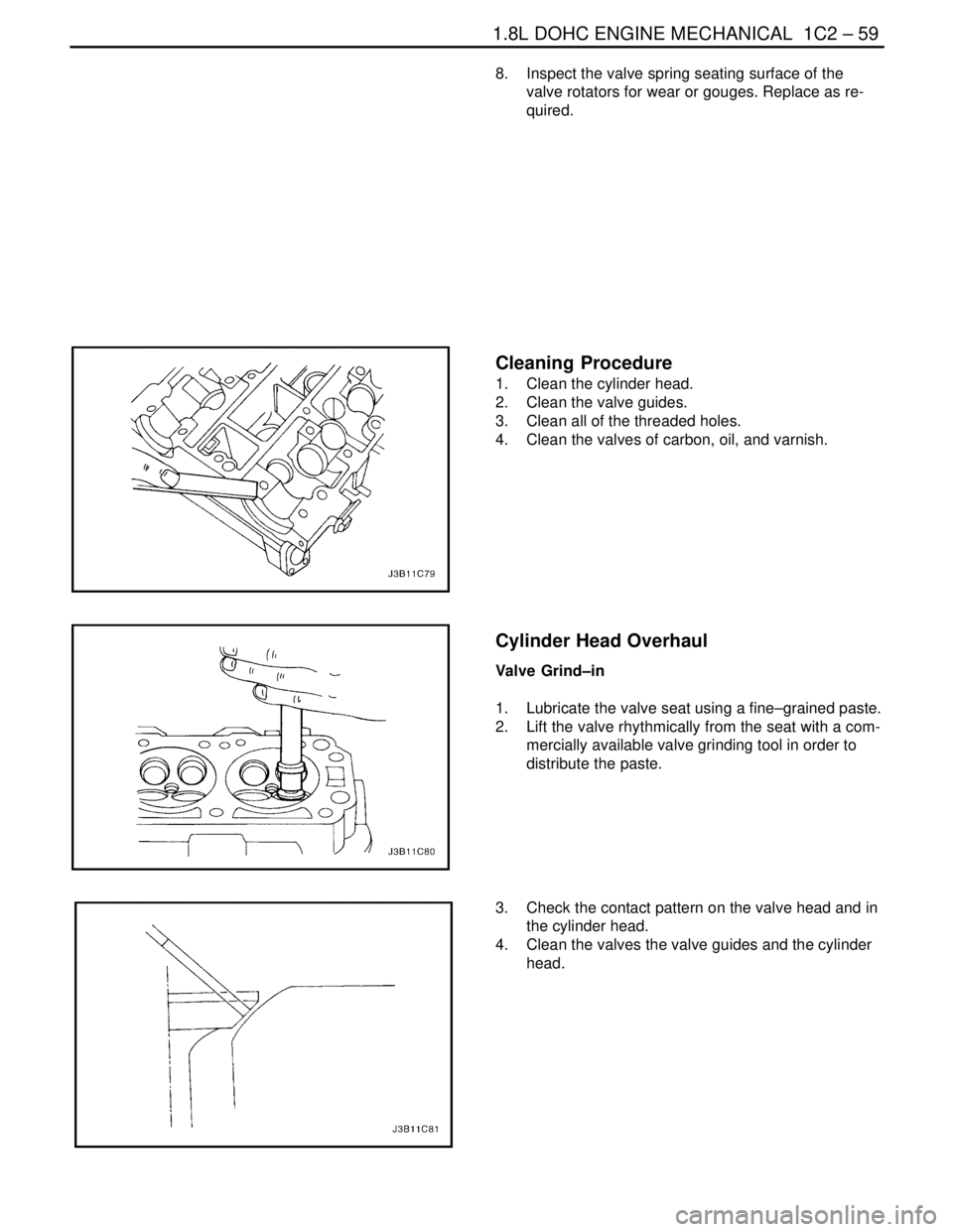
8. Inspect the valve spring seating surface of the
valve rotators for wear or gouges. Replace as re-
quired.
Cleaning Procedure
1. Clean the cylinder head.
2. Clean the valve guides.
3. Clean all of the threaded holes.
4. Clean the valves of carbon, oil, and varnish.
Cylinder Head Overhaul
Valve Grind–in
1. Lubricate the valve seat using a fine–grained paste.
2. Lift the valve rhythmically from the seat with a com-
mercially available valve grinding tool in order to
distribute the paste.
3. Check the contact pattern on the valve head and in
the cylinder head.
4. Clean the valves the valve guides and the cylinder
head.