2004 DAEWOO LACETTI seat
[x] Cancel search: seatPage 276 of 2643

1F – 30IENGINE CONTROLS
DAEWOO V–121 BL4
DIAGNOSIS
SYSTEM DIAGNOSIS
DIAGNOSTIC AIDS
If an intermittent problem is evident, follow the guidelines
below.
Preliminary Checks
Before using this section you should have already per-
formed the ”On–Board Diagnostic System Check.”
Perform a thorough visual inspection. This inspection can
often lead to correcting a problem without further checks
and can save valuable time. Inspect for the following con-
ditions:
S Engine control module (ECM) grounds for being
clean, tight, and in their proper location.
S Vacuum hoses for splits, kinks, collapsing and prop-
er connections as shown on the Vehicle Emission
Control Information label. Inspect thoroughly for
any type of leak or restriction.
S Air leaks at the throttle body mounting area and the
intake manifold sealing surfaces.
S Ignition wires for cracks, hardness, proper routing,
and carbon tracking.
S Wiring for proper connections.
S Wiring for pinches or cuts.
Diagnostic Trouble Code Tables
Do not use the Diagnostic Trouble Code (DTC) tables to
try to correct an intermittent fault. The fault must be pres-
ent to locate the problem.
Incorrect use of the DTC tables may result in the unneces-
sary replacement of parts.
Faulty Electrical Connections or Wiring
Most intermittent problems are caused by faulty electrical
connections or wiring. Perform a careful inspection of sus-
pect circuits for the following:
S Poor mating of the connector halves.
S Terminals not fully seated in the connector body.
S Improperly formed or damaged terminals. All con-
nector terminals in a problem circuit should be care-
fully inspected, reformed, or replaced to insure con-
tact tension.S Poor terminal–to–wire connection. This requires
removing the terminal from the connector body.
Road Test
If a visual inspection does not find the cause of the prob-
lem, the vehicle can be driven with a voltmeter or a scan
tool connected to a suspected circuit. An abnormal voltage
or scan tool reading will indicate that the problem is in that
circuit.
If there are no wiring or connector problems found and a
DTC was stored for a circuit having a sensor, except for
DTC P0171 and DTC P0172, replace the sensor.
Fuel System
Some intermittent driveability problems can be attributed
to poor fuel quality. If a vehicle is occasionally running
rough, stalling, or otherwise performing badly, ask the cus-
tomer about the following fuel buying habits:
S Do they always buy from the same source? If so,
fuel quality problems can usually be discounted.
S Do they buy their fuel from whichever fuel station
that is advertising the lowest price? If so, check the
fuel tank for signs of debris, water, or other contam-
ination.
IDLE LEARN PROCEDURE
Whenever the battery cables, the engine control module
(ECM), or the ECM fuse is disconnected or replaced, the
following idle learn procedure must be performed:
1. Turn the ignition ON for 5 seconds.
2. Turn the ignition OFF for 5 seconds.
3. Turn the ignition ON for 5 seconds.
4. Start the engine in park/neutral.
5. Allow the engine to run until the engine coolant is
above 185° F (85°C ).
6. Turn the A/C ON for 10 seconds, if equipped.
7. Turn the A/C OFF for 10 seconds, if equipped.
8. If the vehicle is equipped with an automatic trans-
axle, apply the parking brake. While pressing the
brake pedal, place the transaxle in D (drive).
9. Turn the A/C ON for 10 seconds, if equipped.
10. Turn the A/C OFF for 10 seconds, if equipped.
11. Turn the ignition OFF. The idle learn procedure is
complete.
Page 328 of 2643

1F – 82IENGINE CONTROLS
DAEWOO V–121 BL4
IDLE AIR CONTROL SYSTEM CHECK (1.8L DOHC)
Circuit Description
The Engine Control Module (ECM) controls the engine idle
speed with the Idle Air Control (IAC) valve. To increase the
idle speed, the ECM pulls the IAC pintle away from its seat,
allowing more air to pass by the throttle body. To decrease
the idle speed, it extends the IAC valve pintle toward its
seat, reducing bypass air flow. A scan tool will read the
ECM commands to the IAC valve in counts. The higher
counts indicate more air bypass (higher idle). The lower
counts indicate less air is allowed to bypass (lower idle).
Diagnostic Aids
If the idle is too high, stop the engine. Fully extend the Idle
Air Control (IAC) valve with a IAC driver. Start the engine.
If the idle speed is above 800 rpm, locate and repair the
vacuum leak. Also, check for a binding throttle plate or
throttle linkage or an incorrect base idle setting.
Test Description
The number(s) below refer to step(s) on the diagnostic
table.
2. The IAC valve is extended and retracted by the IAC
driver. IAC valve movement is verified by an engine
speed change. If no change in engine speed oc-
curs, the valve can be removed from the throttle
body and tested. Connect the IAC driver to the re-
moved IAC valve and turn the ignition ON. Do not
start the engine.5. This step checks the quality of the IAC valve move-
ment in Step 2. Fully extending the IAC valve may
cause an engine stall. This may be normal.
6. Steps 2 and 5 verify proper IAC valve operation.
This step checks the IAC circuit for a wiring or ECM
fault.
Idle Air Control Valve Reset Procedure
Whenever the battery cable or the Engine Control Module
(ECM) connector or the ECM fuse Ef11 is disconnected or
replaced, the following idle learn procedure must be per-
formed:
1. Turn the ignition ON for 5 seconds.
2. Turn the ignition OFF for 10 seconds.
3. Turn the ignition ON for 5 seconds.
4. Start the engine in park/neutral.
5. Allow the engine to run until the engine coolant is
above 185°F (85°C).
6. Turn the A/C ON for 10 seconds, if equipped.
7. Turn the A/C OFF for 10 seconds, if equipped.
8. If the vehicle is equipped with an automatic trans-
axle, apply the parking brake. While pressing the
brake pedal, place the transaxle in D (drive).
9. Turn the A/C ON for 10 seconds, if equipped.
10. Turn the A/C OFF for 10 seconds, if equipped.
11. Turn the ignition OFF. The idle learn procedure is
complete.
Page 391 of 2643

ENGINE CONTROLS 1F – 145
DAEWOO V–121 BL4
DIAGNOSTIC TROUBLE CODE (DTC) P0135
FRONT HEATED OXYGEN SENSOR HEATER CIRCUIT
NOT FUNCTIONING
Circuit Description
Heated oxygen sensors (HO2S) are used for fuel control
and post catalyst monitoring. Each HO2S compares the
oxygen content of the surrounding air with the oxygen con-
tent in the exhaust stream. The HO2S must reach operat-
ing temperature to provide an accurate voltage signal. A
heating element inside the HO2S minmizes the time re-
quired for the sensor to reach operating temperature. Volt-
age is provided to the heater by the ignition 1 voltage cir-
cuit through a fuse. With the engine running, ground is
provided to the heater by the HO2S heater low control cir-
cuit, through a low side driver within the engine control
module (ECM). The ECM monitors the current flow
through the heater for diagnosis.
If the ECM detects that the HO2S heater current is above
or blelow a specified range, DTC P0135 seats.
Conditions for Setting the DTC
S DTCs P0106, P0117, P0118, P1017 are not set.
S Engine run time is greater than 30 seconds.
S Filtered O2 heater current is less than 0.1 amps.
Action Taken When the DTC SetsS The Malfunction Indicator Lamp (MIL) will illuminate
after three consecutive trip with a fail.
S The ECM will record operating conditions at the
time the diagnostic fails. This information will be
stored in the Freeze Frame and Failure Records
buffers.
S A history Diagnostic Trouble Code (DTC) is stored.
Conditions for Clearing the MIL/DTC
S The MIL will turn off after three consecutive ignition
cycles in which the diagnostic runs without a fault.
S A history DTC will clear after 40 consecutive warm–
up cycles without a fault.
S DTC(s) can be cleared by using the scan tool.
Diagnostic Aids
An intermittent may be caused by rubbed through wire in-
sulation or a wire contacting the exhaust.
Check for poor connection or damaged harness – inspect
harness connectors for the following conditions:
S Improper mating
S Broken locks
S Improperly formed
S Damaged terminals
S Poor terminal–to–wire connection
Page 631 of 2643

ENGINE CONTROLS 1F – 385
DAEWOO V–121 BL4
DIAGNOSTIC TROUBLE CODE (DTC) P0135
FRONT HEATED OXYGEN SENSOR (HO2S1) HEATER
CIRCUIT NOT FUNCTIONING
Circuit Description
Heated oxygen sensors (HO2S) are used for fuel control
and post catalyst monitoring. Each HO2S compares the
oxygen content of the surrounding air with the oxygen con-
tent in the exhaust stream. The HO2S must reach operat-
ing temperature to provide an accurate voltage signal. A
heating element inside the HO2S minmizes the time re-
quired for the sensor to reach operating temperature. Volt-
age is provided to the heater by the ignition 1 voltage cir-
cuit through a fuse. With the engine running, ground is
provided to the heater by the HO2S heater low control cir-
cuit, through a low side driver within the engine control
module (ECM). The ECM monitors the current flow
through the heater for diagnosis.
If the ECM detects that the HO2S heater current is above
or blelow a specified range, DTC P0135 seats.
Conditions for Setting the DTC
S DTCs P0106, P0117, P0118, P1017 are not set.
S Engine run time is greater than 200 seconds.
S Filtered O2 heater current is less than 0.025 amps.
Action Taken When the DTC SetsS The Malfunction Indicator Lamp (MIL) will illuminate
after three consecutive ignition cycle with a fail.
S The ECM will record operating conditions at the
time the diagnostic fails. This information will be
stored in the Freeze Frame and Failure Records
buffers.
S A history Diagnostic Trouble Code (DTC) is stored.
Conditions for Clearing the MIL/DTC
S The MIL will turn off after three consecutive ignition
cycles in which the diagnostic runs without a fault.
S A history DTC will clear after 40 consecutive warm–
up cycles without a fault.
S DTC(s) can be cleared by using the scan tool.
Diagnostic Aids
An intermittent may be caused by rubbed through wire in-
sulation or a wire contacting the exhaust.
Check for poor connection or damaged harness – inspect
harness connectors for the following conditions:
S Improper mating
S Broken locks
S Improperly formed
S Damaged terminals
S Poor terminal–to–wire connection
Page 747 of 2643

ENGINE CONTROLS 1F – 501
DAEWOO V–121 BL4
DIAGNOSTIC TROUBLE CODE (DTC) P0506
IDLE SPEED RPM LOWER THAN DESIRED IDLE SPEED
Circuit Description
The Engine Control Module (ECM) controls the air enter-
ing into the engine with an Idle Air Control (IAC) Valve. To
increase the idle rpm, the ECM commands the pintle in-
side the IAC valve away from the throttle body seat. This
allows more air to bypass through the throttle blade. To de-
crease the rpm the ECM commands the pintle towards the
throttle body seat. This reduces the amount of air bypass-
ing the throttle blade. A scan tool will read the IAC valve
pintle position in counts. The higher the counts, the more
air that is allowed to bypass the throttle blade. This Diag-
nostic Trouble Code (DTC) determines if a low idle condi-
tion exists as defined as 100 rpm below the desired idle
rpm.
Conditions for Setting the DTC
S No intrusive tests are active.
S DTC(s) P0106, P0107, P0108, P0112, P0113,
P0117, P0118, P0122, P0123, P0131, P0132,
P0133, P0135, P0141, P1133, P1134, P0171,
P01167, P1171, P0172, P0201, P0202, P0203,
P0204, P0300, P0336, P0337, P0341, P0342,
P0351, P0352, P0402, P0404, P1404, P0405,
P0406, P0443, and P0502 are not set.
S Engine is running more than 60 seconds.
S Barometric Pressure (BARO) is greater than 72
kPa (10.4 psi).
S Engine Coolant Temperature (ECT) is greater than
60°C (140°F).
S Ignition voltage is between 11 and 16 volts.
S Manifold Absolute Pressure is less than 60 kPa (8.7
psi).
S IAC valve is controlled fully opened.
S All of the above must be met for greater than 5 sec-
onds.Action Taken When the DTC Sets
S The Malfunction Indicator Lamp (MIL) will illuminate
after three consecutive ignition cycle with a fail.
S The ECM will record operating conditions at the
time the diagnostic fails. This information will be
stored in the Freeze Frame and Failure Records
buffers.
S A history DTC is stored.
Conditions for Clearing the MIL/DTC
S The MIL will turn off after four consecutive ignition
cycles in which the diagnostic runs without a fault.
S A history DTC will clear after 40 consecutive warm–
up cycles without a fault.
S DTC(s) can be cleared by using the scan tool.
S Disconnecting the ECM battery feed for more than
10 seconds.
Diagnostic Aids
Inspect the IAC valve electrical connection for proper mat-
ing.
Inspect the wiring harness for damage.
Inspect the throttle stop screw for signs of tampering.
Inspect the throttle linkage for signs of binding or exces-
sive wear.
A slow or unstable idle may be caused by one of the follow-
ing conditions:
S Fuel system too rich or too lean.
S Foreign material in the throttle body bore or in the
air induction system.
S A leaking or restricted intake manifold.
S Excessive engine overloading. Check for seized
pulleys, pumps, or motors on the accessory drive.
S Overweight engine oil.
Page 750 of 2643

1F – 504IENGINE CONTROLS
DAEWOO V–121 BL4
DIAGNOSTIC TROUBLE CODE (DTC) P0507
IDLE SPEED RPM HIGHER THAN DESIRED IDLE SPEED
Circuit Description
The Engine Control Module (ECM) controls the air enter-
ing into the engine with an Idle Air Control (IAC) Valve. To
increase the idle rpm, the ECM commands the pintle in-
side the IAC valve away from the throttle body seat. This
allows more air to bypass through the throttle blade. To de-
crease the rpm the ECM commands the pintle towards the
throttle body seat. This reduces the amount of air bypass-
ing the throttle blade. A scan tool will read the IAC valve
pintle position in counts. The higher the counts, the more
air that is allowed to bypass the throttle blade. This Diag-
nostic Trouble Code (DTC) determines if a high idle condi-
tion exists as defined as 200 rpm above the desired idle
rpm.
Conditions for Setting the DTC
S No intrusive tests are active.
S DTC(s) P0106, P0107, P0108, P0112, P0113,
P0117, P0118, P0122, P0123, P0131, P0132,
P0133, P0135, P0141, P1133, P1134, P0171,
P1167, P1171, P0172, P0201, P0202, P0203,
P0204, P0300, P0336, P0337, P0341, P0342,
P0351, P0352, P0402, P0404, P1404, P0405,
P0406, P0441, P0443, and P0502 are not set.
S Engine is running more than 60 seconds.
S Barometric Pressure (BARO) is greater than 72
kPa (10.4 psi).
S Engine Coolant Temperature (ECT) is greater than
60°C (140°F).
S Ignition voltage is between 11 and 16 volts.
S The Intake Air Temperature (IAT) is greater than
–20°C (–4°F).
S IAC valve is controlled fully closed.S All of the above must be met for greater than 5 sec-
onds.
S Idle engine speed error is greater than 200 rpm for
10 seconds.
Action Taken When the DTC Sets
S The Malfunction Indicator Lamp (MIL) will illuminate
after three consecutive ignition cycle with a fail.
S The ECM will record operating conditions at the
time the diagnostic fails. This information will be
stored in the Freeze Frame and Failure Records
buffers.
S A history DTC is stored.
Conditions for Clearing the MIL/DTC
S The MIL will turn off after four consecutive ignition
cycles in which the diagnostic runs without a fault.
S A history DTC will clear after 40 consecutive warm–
up cycles without a fault.
S DTC(s) can be cleared by using the scan tool.
S Disconnecting the ECM battery feed for more than
10 seconds.
Diagnostic Aids
Inspect the IAC valve electrical connection for proper mat-
ing.
Inspect the wiring harness for damage.
Inspect the throttle stop screw for signs of tampering.
Inspect the throttle linkage for signs of binding or exces-
sive wear.
Inspect the positive crankcase ventilation (PCV) valve and
PCV hose.
A slow or unstable idle may be caused by one of the follow-
ing conditions:
Page 820 of 2643

1F – 574IENGINE CONTROLS
DAEWOO V–121 BL4
SYMPTOM DIAGNOSIS
IMPORTANT PRELIMINARY CHECKS
Important : Several symptom procedures call for a careful visual/physical inspection. Always perform the visual/physical
test first. Visual inspections may lead to correcting a problem without further checks and can save valuable time.
Step
ActionValue(s)YesNo
1Perform an On–Board Diagnostic (EOBD) System
Check.
Is the check complete?–Go toStep 2Go to”On–
Board Diagnos-
tic System
Check”
21. Inspect all of the engine control module (ECM)
ground connections.
2. Inspect all of the vacuum hoses for splits,
kinks, and proper connections.
3. Check for air leaks at all of the mounting areas
of the intake manifold sealing surfaces.
4. Inspect the ignition wires for cracking, hard-
ness, proper routing, and carbon tracking.
5. Inspect the wiring for proper connections,
pinches, and cuts.
Are all checks complete?–Go to Appropri-
ate Symptom
Table–
INTERMITTENTS
Definition : The problem may or may not illuminate the
Malfunction Indicator Lamp (MIL) or store a diagnostic
trouble code (DTC).Important : Do not use the DTC tables for intermittent
problems. A fault must be present in order to locate the
problem. If a fault is intermittent, use of DTC tables may
result in the replacement of good parts.
Step
ActionValue(s)YesNo
1Were the Important Preliminary Checks performed?–Go toStep 2Go to
”Important Pre-
liminary
Checks”
21. Perform a careful inspection of any suspect
circuits.
2. Inspect for poor mating of the connector
halves, or terminals not fully seated into the
connector body.
3. Inspect for improperly formed or damaged ter-
minals.
4. Inspect for poor terminal to wire connections.
This requires removing the terminal from the
connector body to inspect it.
Are any problems present?–Go toStep 3Go toStep 4
3Repair the electrical connections as needed.
Is the repair complete?–System OK–
4Road test the vehicle with a voltmeter connected to
a suspected circuit or a scan tool connected to the
Data Link Connector (DLC).
Did the voltmeter or the scan tool indicate an abnor-
mal voltage or scan reading?–Go toStep 5Go toStep 6
Page 842 of 2643
1F – 596IENGINE CONTROLS
DAEWOO V–121 BL4
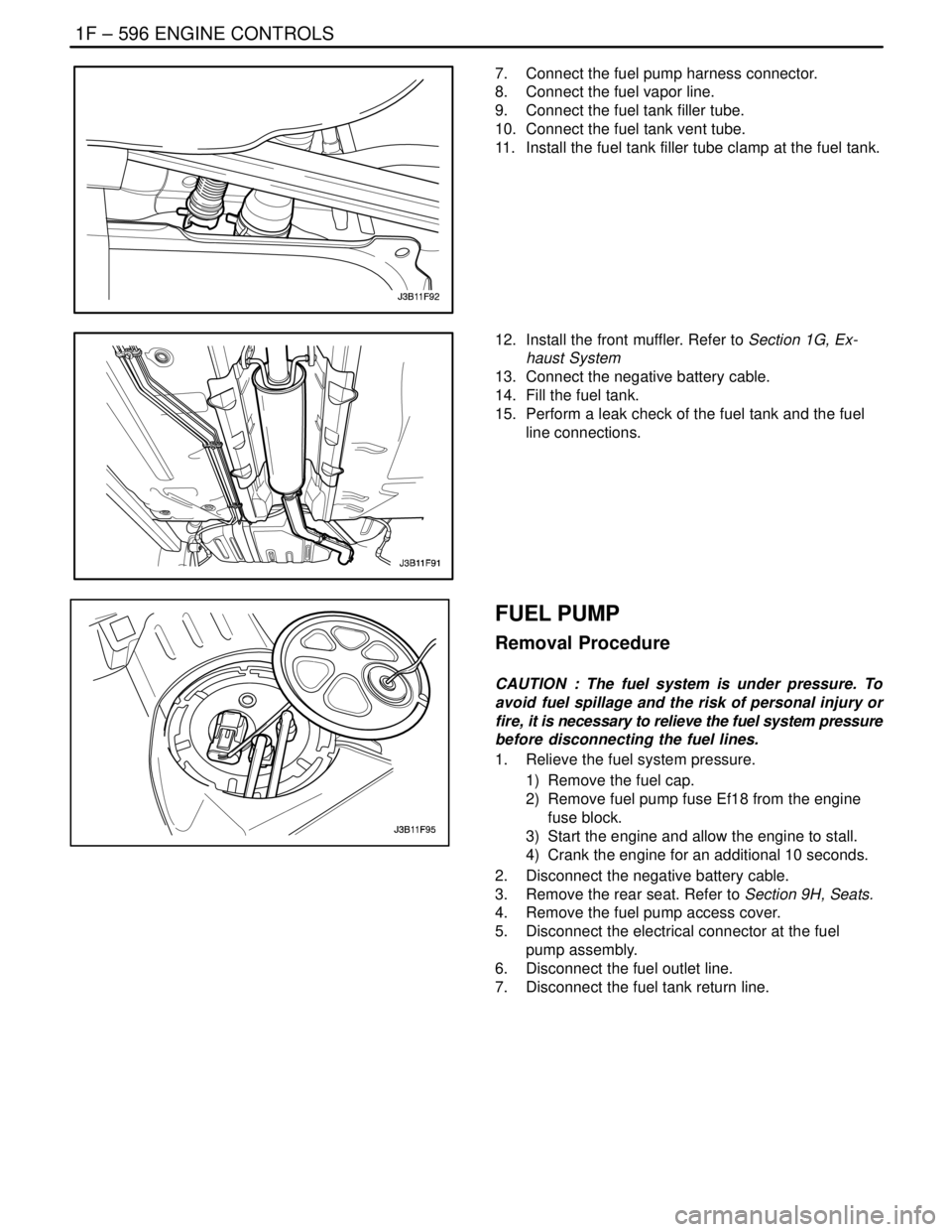
7. Connect the fuel pump harness connector.
8. Connect the fuel vapor line.
9. Connect the fuel tank filler tube.
10. Connect the fuel tank vent tube.
11. Install the fuel tank filler tube clamp at the fuel tank.
12. Install the front muffler. Refer to Section 1G, Ex-
haust System
13. Connect the negative battery cable.
14. Fill the fuel tank.
15. Perform a leak check of the fuel tank and the fuel
line connections.
FUEL PUMP
Removal Procedure
CAUTION : The fuel system is under pressure. To
avoid fuel spillage and the risk of personal injury or
fire, it is necessary to relieve the fuel system pressure
before disconnecting the fuel lines.
1. Relieve the fuel system pressure.
1) Remove the fuel cap.
2) Remove fuel pump fuse Ef18 from the engine
fuse block.
3) Start the engine and allow the engine to stall.
4) Crank the engine for an additional 10 seconds.
2. Disconnect the negative battery cable.
3. Remove the rear seat. Refer to Section 9H, Seats.
4. Remove the fuel pump access cover.
5. Disconnect the electrical connector at the fuel
pump assembly.
6. Disconnect the fuel outlet line.
7. Disconnect the fuel tank return line.