Page 892 of 2643
 CONNECTOR INFORMATION
Connector
Number
Te r m i n a l
NumberColorConnecting Wiring
HarnessConnector Position
C10121 PinWhiteBody � Engine Fuse BlockEngine F")
POSITION OF CONNECTORS AND GROUNDSW2–3
2) CONNECTOR INFORMATION
Connector
Number
Te r m i n a l
NumberColorConnecting Wiring
HarnessConnector Position
C10121 PinWhiteBody � Engine Fuse BlockEngine Fuse Block
C10211 P i nWhiteBody � Engine Fuse BlockEngine Fuse Block
C10310 PinWhiteEngine � Engine Fuse BlockEngine Fuse Block
C10424 PinWhiteFront � Engine Fuse BlockEngine Fuse Block
C1054 PinWhiteBody � Engine Fuse BlockEngine Fuse Block
C10620 PinWhiteEngine � Engine Fuse BlockEngine Fuse Block
C1072 PinWhiteABS � Engine Fuse BlockEngine Fuse Block
C10824 PinBlackBody � EngineLeft Engine Fuse Block
C1094 PinWhiteEngine � FrontUnder Engine Fuse Block
C11012 PinWhiteABS � BodyBelow Engine Fuse Block
C 1112 PinBlackABS � FrontBelow Engine Fuse Block
C1122 PinBlackFront – HornCenter Cross Member Panel
C11316 PinBlackBody � FrontBehind ECM Bracket
C20176 PinBlackI.P � I.P Fuse BlockI.P Fuse Block
C20289 PinWhiteI.P � BodyLeft CO–Driver Leg Room
C2048 PinWhiteRoof � Body (W/O Rain Sensor)Left CO–Driver Leg Room
C20414 PinWhiteRoof � Body(W/ Rain Sensor)Left CO–Driver Leg Room
C20622 PinWhiteI.P � TCMUpper Driver Leg Room
C2076 PinWhiteAir Bag � I.PUpper Left Driver Leg Room
C20815 PinWhiteI.P � FAT CBehind Glove Box
C20920 PinBlackFAT C � FAT C . A u xBetween Heater Core and
Evaporator Core
C2106 PinWhiteI.P � ConsoleBelow Console Box
C3018 PinWhiteAir Bag � BodyFront SDM
C3024 PinBlackRR. ABS � BodyCenter Rear Cross Member
C35133 PinGrayBody � Front Light DoorUnder CO–Driver A Pillar
C36133 PinGrayBody � Front Right DoorUnder Driver A Pillar
C37112 PinWhiteBody � Rear Light DoorUnder Left B Pillar
C38112 PinWhiteBody � Rear Right DoorUnder Right B Pillar
C401 (N/B)8 PinWhiteTrunk � BodyInside Right Trunk Side Cover
C401 (H/B)6 PinWhiteTrunk � BodyInside Right Trunk Side Cover
C4026 PinWhiteTrunk LID � BodyInside Right Trunk Side Cover
C4036 PinWhiteT/Gate. EXT. – BodyInside Left C Pillar
C4048 PinWhiteT/Gate. EXT. – BodyInside Left C Pillar
C4058 PinWhiteT/Gate. EXT. – T/GateBeside Left Rear Wiper Motor
C4066 PinWhiteT/Gate. EXT. – T/GateBeside Left Rear Wiper Motor
3) GROUND INFORMATION
Ground Number
Wiring HarnessGround Position
G101FrontBehind Left Head Lamp
G102FrontBehind Right Head Lamp
G103BatteryLeft Battery
G104EngineUnder Start Motor
G105BatteryUnder Start Motor
G106ABSBelow EBCM
G107Engine(MR–140/HV–240)Under Start Motor
G201I.PLeft I/P Fuse Block
G202Air BagBehind Left Audio Bracket
G203I.PBehind Left Audio Bracket
G205RoofUpper Driver Leg Room
G301BodyBelow Driver Cross Member Floor Panel
G302BodyBelow Left C Pillar
G303BodyBelow Left CO–Driver Leg Room
G401TrunkCenter Trunk Lower Back Panel
G402T/Gate. EXT.Inside Driver C Pillar
4) SPLICE PACK INFORMATION
Splice Pack Number
ColorWiring HarnessGround Position
S101BlackEngine(MR–140/HV–240)Upper Transmission
S202BlackI.PBehind Cluster
S203RedI.PBehind Audio Mounting
S204MagentaI.PBehind Audio Mounting
S205OrangeTCM (MR–140/HV–240)Upper Driver Leg Room
S301BlueBodyLeft CO–Driver Leg Room
S302BrownBodyLeft CO–Driver Leg Room
Page 1172 of 2643
5–12WELECTRICAL WIRING DIAGRAMS
2) FUEL PUMP, INJECTOR & HEATED O2 SENSOR CIRCUITa. CONNECTOR INFORMATION
CONNECTOR(NO.)
(PIN NO. COLOR)
CONNECTING, WIRING HARNESSCONNECTOR POSITION
C101 (21 Pin, White)Body � Engine Fuse BlockEngine Fuse Block
C102 (11 Pin, White)Body � Engine Fuse BlockEngine Fuse Block
C103 (10 Pin, White)Engine � Engine Fuse BlockEngine Fuse Block
C106 (20 Pin, White)Engine � Engine Fuse BlockEngine Fuse Block
C109 (4 Pin, White)Engine � FrontUnder Engine Fuse Block
C201 (76 Pin, Black)I.P � I.P Fuse BlockI.P Fuse Block
C202 (89 Pin, White)I.P � BodyLeft CO–Driver Leg Room
G107Engine (MR–140/HV–240)Under Start Motor
G302BodyBelow Left C Pillar
b. CONNECTOR IDENTIFICATION SYMBOL & PIN NUMBER POSITION
J3B1P003
Page 1184 of 2643
5–24WELECTRICAL WIRING DIAGRAMS
2) FUEL PUMP, INJECTOR & O2 SENSOR CIRCUITa. CONNECTOR INFORMATION
CONNECTOR(NO.)
(PIN NO. COLOR)
CONNECTING, WIRING HARNESSCONNECTOR POSITION
C101 (21 Pin, White)Body � Engine Fuse BlockEngine Fuse Block
C102 (11 Pin, White)Body � Engine Fuse BlockEngine Fuse Block
C103 (10 Pin, White)Engine � Engine Fuse BlockEngine Fuse Block
C106 (20 Pin, White)Engine � Engine Fuse BlockEngine Fuse Block
C201 (76 Pin, Black)I.P � I.P Fuse BlockI.P Fuse Block
C202 (89 Pin, White)I.P � BodyLeft CO–Driver Leg Room
S101 (Black)Engine (MR–140/HV–240)Upper Transmission
G107Engine (MR–140/HV–240)Under Start Motor
G302BodyBelow Left C Pillar
b. CONNECTOR IDENTIFICATION SYMBOL & PIN NUMBER POSITION
J3B1P009
Page 1196 of 2643
5–36WELECTRICAL WIRING DIAGRAMS
2) FUEL PUMP, INJECTOR, FUEL CONNECTOR & CMP SENSOR CIRCUITa. CONNECTOR INFORMATION
CONNECTOR(NO.)
(PIN NO. COLOR)
CONNECTING, WIRING HARNESSCONNECTOR POSITION
C101 (21 Pin, White)Body � Engine Fuse BlockEngine Fuse Block
C102 (11 Pin, White)Body � Engine Fuse BlockEngine Fuse Block
C103 (10 Pin, White)Engine � Engine Fuse BlockEngine Fuse Block
C106 (20 Pin, White)Engine � Engine Fuse BlockEngine Fuse Block
C108 (24 Pin, Black)Body � EngineLeft Engine Fuse Block
C113 (16 Pin, Black)Body � FrontBehind ECM Bracket
C201 (76 Pin, Black)I.P � I.P Fuse BlockI.P Fuse Block
C202 (89 Pin, White)I.P � BodyLeft CO–Driver Leg Room
C208 (15 Pin, White)I.P � FAT CBehind Glove Box
C209 (20 Pin, Black)FAT C � FAT C . A u xBetween Heater Core and Evaporator Core
G302BodyBelow Left C Pillar
b. CONNECTOR IDENTIFICATION SYMBOL & PIN NUMBER POSITION
Page 1218 of 2643
5–58WELECTRICAL WIRING DIAGRAMS
2) POWER SUPPLY, GROUND, PNP SWITCH, CLUSTER & ECM CIRCUIT : HATCH BACKa. CONNECTOR INFORMATION
CONNECTOR(NO.)
(PIN NO. COLOR)
CONNECTING, WIRING HARNESSCONNECTOR POSITION
C105 (4 Pin, White)Body � Engine Fuse BlockEngine Fuse Block
C108 (24 Pin, Black)Body � EngineLeft Engine Fuse Block
C201 (76 Pin, Black)I.P � I.P Fuse BlockI.P Fuse Block
C202 (89 Pin, White)I.P � BodyLeft CO–Driver Leg Room
C206 (22 Pin, White)I.P � TCMUpper Driver Leg Room
C401 (6 Pin, White)Trunk – BodyInside Right Trunk Side Cover
C403 (6 Pin, White)T/Gate. EXT. � BodyInside Left C Pillar
C405 (8 Pin, White)T/Gate. EXT. � T/GateBeside Left Rear Wiper Motor
G201I.PLeft I.P Fuse Block
G402T/Gate. EXT.Inside Driver C Pillar
b. CONNECTOR IDENTIFICATION SYMBOL & PIN NUMBER POSITION
Page 1250 of 2643
5–90WELECTRICAL WIRING DIAGRAMS
3) LAMP (LICENSE PLATE & FRONT/REAR POSITION) CIRCUIT : NOTCH BACKa. CONNECTOR INFORMATION
CONNECTOR(NO.)
(PIN NO. COLOR)
CONNECTING, WIRING HARNESSCONNECTOR POSITION
C101 (21 Pin, White)Body � Engine Fuse BlockEngine Fuse Block
C104 (24 Pin, White)Front � Engine Fuse BlockEngine Fuse Block
C201 (76 Pin, Black)I.P � I.P Fuse BlockI.P Fuse Block
C202 (89 Pin, White)I.P � BodyLeft CO–Driver Leg Room
C401 (8 Pin, White)Trunk � BodyInside Right Trunk Side Cover
C402 (6 Pin, White)Trunk LID � BodyInside Right Trunk Side Cover
G101FrontBehind Left Head Lamp
G102FrontBehind Right Head Lamp
G201I.PLeft I.P Fuse Block
G302BodyBelow Left C Pillar
G401TrunkCenter Trunk Lower Back Panel
b. CONNECTOR IDENTIFICATION SYMBOL & PIN NUMBER POSITION
Page 1252 of 2643
5–92WELECTRICAL WIRING DIAGRAMS
4) LAMP (LICENSE PLATE & FRONT/REAR POSITION) CIRCUIT : HATCH BACKa. CONNECTOR INFORMATION
CONNECTOR(NO.)
(PIN NO. COLOR)
CONNECTING, WIRING HARNESSCONNECTOR POSITION
C101 (21 Pin, White)Body � Engine Fuse BlockEngine Fuse Block
C104 (24 Pin, White)Front � Engine Fuse BlockEngine Fuse Block
C201 (76 Pin, Black)I.P � I.P Fuse BlockI.P Fuse Block
C202 (89 Pin, White)I.P � BodyLeft CO–Driver Leg Room
C401 (6 Pin, White)Trunk – BodyInside Right Trunk Side Cover
C403 (6 Pin, White)T/Gate. EXT. � BodyInside Left C Pillar
C405 (8 Pin, White)T/Gate. EXT. � T/GateBeside Left Rear Wiper Motor
G101FrontBehind Left Head Lamp
G102FrontBehind Right Head Lamp
G201I.PLeft I.P Fuse Block
G401TrunkCenter Trunk Lower Back Panel
G402T/Gate. EXT.Inside Driver C Pillar
b. CONNECTOR IDENTIFICATION SYMBOL & PIN NUMBER POSITION
Page 1256 of 2643
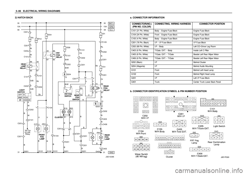
5–96WELECTRICAL WIRING DIAGRAMS
2) HATCH BACKa. CONNECTOR INFORMATION
CONNECTOR(NO.)
(PIN NO. COLOR)
CONNECTING, WIRING HARNESSCONNECTOR POSITION
C101 (21 Pin, White)Body � Engine Fuse BlockEngine Fuse Block
C104 (24 Pin, White)Front � Engine Fuse BlockEngine Fuse Block
C105 (4 Pin, White)Body � Engine Fuse BlockEngine Fuse Block
C201 (76 Pin, Black)I.P � I.P Fuse BlockI.P Fuse Block
C202 (89 Pin, White)I.P � BodyLeft CO–Driver Leg Room
C403 (6 Pin, White)T/Gate. EXT. � BodyInside Left C Pillar
C405 (8 Pin, White)T/Gate. EXT. � T/GateBeside Left Rear Wiper Motor
C406 (6 Pin, White)T/Gate. EXT. � T/GateBeside Left Rear Wiper Motor
S202 (Black)I.PBehind Cluster
S204 (Magenta)I.PBehind Audio Mounting
G101FrontBehind Left Head Lamp
G102FrontBehind Right Head Lamp
G201I.PLeft I.P Fuse Block
G401TrunkCenter Trunk Lower Back Panel
b. CONNECTOR IDENTIFICATION SYMBOL & PIN NUMBER POSITION
 FUEL PUMP, INJECTOR & HEATED O2 SENSOR CIRCUITa. CONNECTOR INFORMATION
CONNECTOR(NO.)
(PIN NO. COLOR)
CONNECTING, WIRING HARNESSCONNECTOR POSITION
C101 (21 Pin, Wh")
 FUEL PUMP, INJECTOR & O2 SENSOR CIRCUITa. CONNECTOR INFORMATION
CONNECTOR(NO.)
(PIN NO. COLOR)
CONNECTING, WIRING HARNESSCONNECTOR POSITION
C101 (21 Pin, White)Bod")
 FUEL PUMP, INJECTOR, FUEL CONNECTOR & CMP SENSOR CIRCUITa. CONNECTOR INFORMATION
CONNECTOR(NO.)
(PIN NO. COLOR)
CONNECTING, WIRING HARNESSCONNECTOR POSITION
C101 (")
 POWER SUPPLY, GROUND, PNP SWITCH, CLUSTER & ECM CIRCUIT : HATCH BACKa. CONNECTOR INFORMATION
CONNECTOR(NO.)
(PIN NO. COLOR)
CONNECTING, WIRING HARNESSCONNECTOR POS")
 LAMP (LICENSE PLATE & FRONT/REAR POSITION) CIRCUIT : NOTCH BACKa. CONNECTOR INFORMATION
CONNECTOR(NO.)
(PIN NO. COLOR)
CONNECTING, WIRING HARNESSCONNECTOR POSITION")
 LAMP (LICENSE PLATE & FRONT/REAR POSITION) CIRCUIT : HATCH BACKa. CONNECTOR INFORMATION
CONNECTOR(NO.)
(PIN NO. COLOR)
CONNECTING, WIRING HARNESSCONNECTOR POSITION")