2004 DAEWOO LACETTI seat
[x] Cancel search: seatPage 1945 of 2643
6C – 28IPOWER STEERING GEAR
DAEWOO V–121 BL4
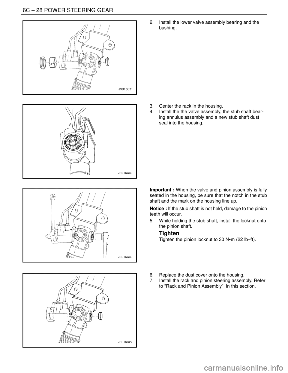
2. Install the lower valve assembly bearing and the
bushing.
3. Center the rack in the housing.
4. Install the the valve assembly, the stub shaft bear-
ing annulus assembly and a new stub shaft dust
seal into the housing.
Important : When the valve and pinion assembly is fully
seated in the housing, be sure that the notch in the stub
shaft and the mark on the housing line up.
Notice : If the stub shaft is not held, damage to the pinion
teeth will occur.
5. While holding the stub shaft, install the locknut onto
the pinion shaft.
Tighten
Tighten the pinion locknut to 30 NSm (22 lb–ft).
6. Replace the dust cover onto the housing.
7. Install the rack and pinion steering assembly. Refer
to ”Rack and Pinion Assembly” in this section.
Page 1949 of 2643
6C – 32IPOWER STEERING GEAR
DAEWOO V–121 BL4
Assembly Procedure
Notice : Coat all of the seals and bushings with power
steering fluid to ensure proper sealing.
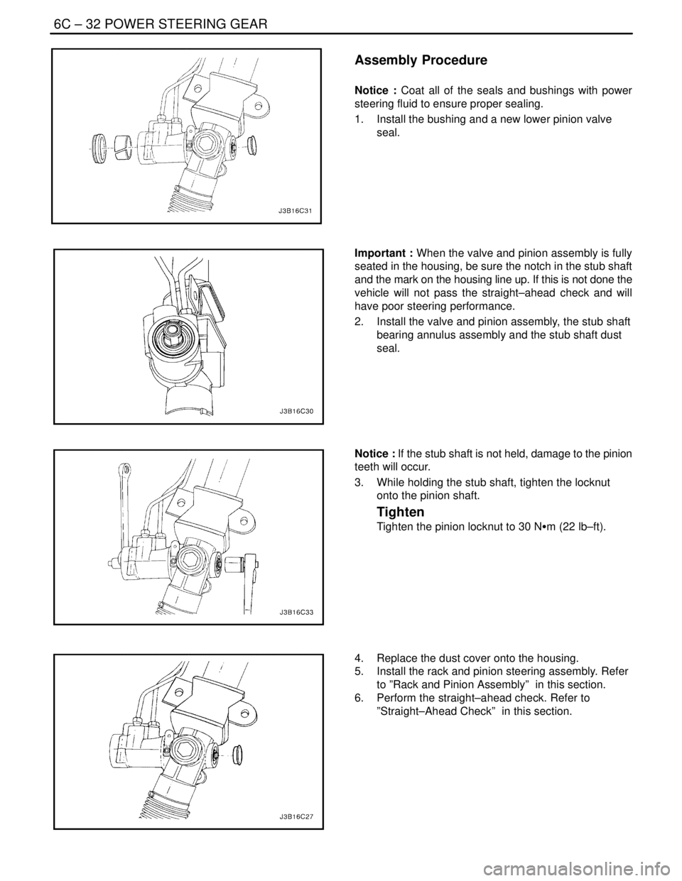
1. Install the bushing and a new lower pinion valve
seal.
Important : When the valve and pinion assembly is fully
seated in the housing, be sure the notch in the stub shaft
and the mark on the housing line up. If this is not done the
vehicle will not pass the straight–ahead check and will
have poor steering performance.
2. Install the valve and pinion assembly, the stub shaft
bearing annulus assembly and the stub shaft dust
seal.
Notice : If the stub shaft is not held, damage to the pinion
teeth will occur.
3. While holding the stub shaft, tighten the locknut
onto the pinion shaft.
Tighten
Tighten the pinion locknut to 30 NSm (22 lb–ft).
4. Replace the dust cover onto the housing.
5. Install the rack and pinion steering assembly. Refer
to ”Rack and Pinion Assembly” in this section.
6. Perform the straight–ahead check. Refer to
”Straight–Ahead Check” in this section.
Page 1959 of 2643

STEERING WHEEL AND COLUMN 6E – 5
DAEWOO V–121 BL4
Column
Noise in the Column
ChecksAction
Check the steering gear–to–column joints for improper
installation.Tighten the steering shaft universal joint pinch bolts.
Replace the steering shaft joints as needed.
Check the steering shaft bearing for wear or damage.Replace the steering shaft bearing.
Check the spherical joint for lack of lubrication.Lubricate the spherical joint.
Check the steering shaft for lack of lubrication.Lubricate the steering shaft bearing.
Check the shaft lock snap ring for improper seating.Adjust the shaft lock snap ring. Replace the shaft lock snap
ring as needed.
High Steering Shaft Effort
ChecksAction
Check the steering shaft bearing for wear or damage.Replace the steering shaft bearing.
Check for an improperly installed or deformed dust seal.Replace the dust seal.
Check for a damaged upper or lower bearing.Replace the upper or the lower bearing.
Check the steering shaft universal joints for a lack of free
movement.Lubricate the steering shaft universal joints. Replace the
steering shaft universal joints as needed.
Lash in the Steering Column
ChecksAction
Check the steering column bracket mounting bolts for im-
proper installation.Tighten the steering column bracket mounting bolts.
Check for broken weld nuts on the steering column jacket.Replace the steering column jacket.
Check for loose steering column housing–to–steering col-
umn jacket support screws.Tighten the support screws.
Loose Steering Wheel
ChecksAction
Check for excessive clearance between the holes in the
steering wheel support or the housing and the pivot–pin di-
ameters.Replace the pivot pins with pivot pins of the correct size.
Check to see if the upper bearing is seated correctly in the
housing.Correctly seat the upper bearing. Replace the upper bear-
ing as needed.
Check for loose steering column housing support screws.Tighten the steering column housing support screws.
Noise When Tilting the Column
ChecksAction
Check for worn upper tilt bumpers.Replace the upper tilt bumpers.
Check for tilt spring binding.Adjust the tilt spring. Replace the tilt spring as needed.
Page 1981 of 2643

HEATING AND VENTILATION SYSTEM 7A – 7
DAEWOO V–121 BL4
StepNo Yes Value(s) Action
131. Check for the following problems:
S Restriction in the cooling system.
S Failed water pump impeller.
S Faulty thermostat.
2. Make repairs to the cooling system, as needed.
Are the repairs complete?–System OKGo to Step 14
141. Install the surge tank cap.
2. With the ignition ON, allow the engine to warm
up for about 20 minutes. Drive the vehicle at 48
km/h (30 mph).
3. Use a thermometer to measure the ambient air
temperature and the discharge air temperature
at the heater outlet.
Does the heater output meet the minimum values
given?Go to ”Heater
Temperature
Specifications”Go to Step 15Go to Step 16
151. Check the vehicle for cold air leaks at the fol-
lowing locations:
S Dash.
S Heater cases.
S Vents.
2. Check under the seat for obstructions.
3. Repair any leaks or obstructions.
Are the repairs complete?–System OK–
161. Turn the ignition OFF.
2. Turn the temperature control knob to full cold,
then rapidly to full hot.
3. Listen for the sound of the temperature door
slam just before it reaches the end of the travel
range of the control knob.
Does the door slam?–Go to Step 18Go to Step 17
171. Check the following aspects of the temperature
door:
S Travel.
S Cables.
S Linkage.
2. Verify the accuracy of the temperature controls
at full hot.
3. Verify the accuracy of the temperature controls
at full cold.
Is the repair complete?–System OK–
181. Set the temperature control knob to full hot.
2. Start the vehicle.
3. Check the temperature of the heater inlet hose
and the heater outlet hose by feel. The air tem-
perature around the hoses should be at least
29°C (84°F).
Is the heater inlet hose hot and the heater outlet
hose warm?–Go to Step 19Go to Step 22
19Check the thermostat. Refer to 2D, Engine Cooling.
Is the thermostat installed and seated properly?–Go to Step 20Go to Step 21
Page 2000 of 2643
7A – 26IHEATING AND VENTILATION SYSTEM
DAEWOO V–121 BL4
Installation Procedure
1. Install the left heater hose to the coolant inlet line
fitting. Slide the end of the heater hose over the
coolant fitting until the hose is seated.
2. Install the right heater hose to the fitting below the
intake manifold. Slide the end of the heater hose
over the fitting until it is seated.
3. Install and seat the other end of each heater hose.
4. Compress and slide the spring clamps into position
on the heater hoses and release the tension.
5. Fill the cooling system.
6. Check the hoses for leaks.
7. Lower the vehicle.
HEATER CORE
(Left–Hand Shown, Right–Hand Drive Similar)
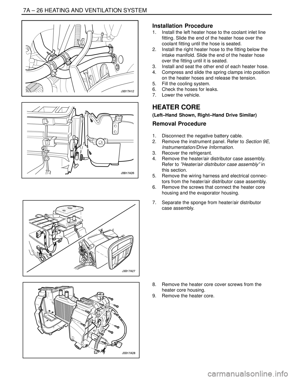
Removal Procedure
1. Disconnect the negative battery cable.
2. Remove the instrument panel. Refer to Section 9E,
Instrumentation/Drive Information.
3. Recover the refrigerant.
4. Remove the heater/air distributor case assembly.
Refer to ”Heater/air distributor case assembly” in
this section.
5. Remove the wiring harness and electrical connec-
tors from the heater/air distributor case assembly.
6. Remove the screws that connect the heater core
housing and the evaporator housing.
7. Separate the sponge from heater/air distributor
case assembly.
8. Remove the heater core cover screws from the
heater core housing.
9. Remove the heater core.
Page 2002 of 2643

7A – 28IHEATING AND VENTILATION SYSTEM
DAEWOO V–121 BL4
GENERAL DESCRIPTION
AND SYSTEM OPERATION
HEATING AND VENTILATION
SYSTEMS
The base heater system is designed to provide heating,
ventilation, windshield defrosting, side window defogging,
and on some vehicles, heating directly to the rear seat
area.
The heater and fan assembly blower regulates the airflow
from the air inlet for further processing and distribution.
The heater core transfers the heat from the engine coolant
to the inlet air.
The temperature door regulates the amount of the air that
passes through the heater core. The temperature door
also controls the temperature of the air by controlling the
mix of the heated air and the ambient air.
The mode door regulates the flow and the distribution of
the processed air to the heater ducts and to the defroster
ducts.
This console–mounted heating and ventilation panel con-
tains the following:
The Rotary Temperature Control Knob
1. The Rotary Temperature Control Knob
S Actuates by cable.
S Raises the temperature of the air entering the
vehicle by rotation toward the right, or the red
portion of the knob.
2. The Rotary Blower Control Knob
S Turns ON to operate the blower motor at four
speeds.
S Turns OFF to stop the blower.
S Operates completely independently both from
the mode control that regulates the defroster
door and from the temperature control knob.S Changes the fan speed in any mode and at any
temperature setting.
3. The Rotary Mode Control Knob
S Actuates by cable.
S Regulates the air distribution between the wind-
shield, the instrument panel, and the floor vents.
Two Push Knobs
1. The Rear Window Defogger Push Knob
S Controls the rear window defogger.
S Turns ON the rear window defogger when the
push knob is pressed and the indicator lamp is
illuminated.
2. The A/C Push Knob (if the vehicle is equipped with
air conditioning)
S Controls the A/C.
S Turns the A/C ON when the push knob is down.
However, if the blower control knob is OFF, the
A/C system is OFF, regardless of the position of
the A/C knob.
Fresh Air Control Level Or Push Knob
1. The Fresh Air Control Level
S Operates by cable.
S Switches between recirculating passenger
compartment air and bringing outside air into the
passenger compartment.
S Draws in outside air when the lever is moved to
the right.
S Recirculates inside air when the lever is moved
to the left.
2. The Fresh Air Control Push Knob
S Operates by cable.
S Switches between recirculating passenger
compartment air and bringing outside air into the
passenger compartment.
S Draws in outside air when knob is off.
S Recirculates inside air when the knob is down
with the indicator lamp illuminated.
Page 2006 of 2643
7B – 4IMANUAL CONTROL HEATING, VENTILATION AND AIR CONDITIONING SYSTEM
DAEWOO V–121 BL4
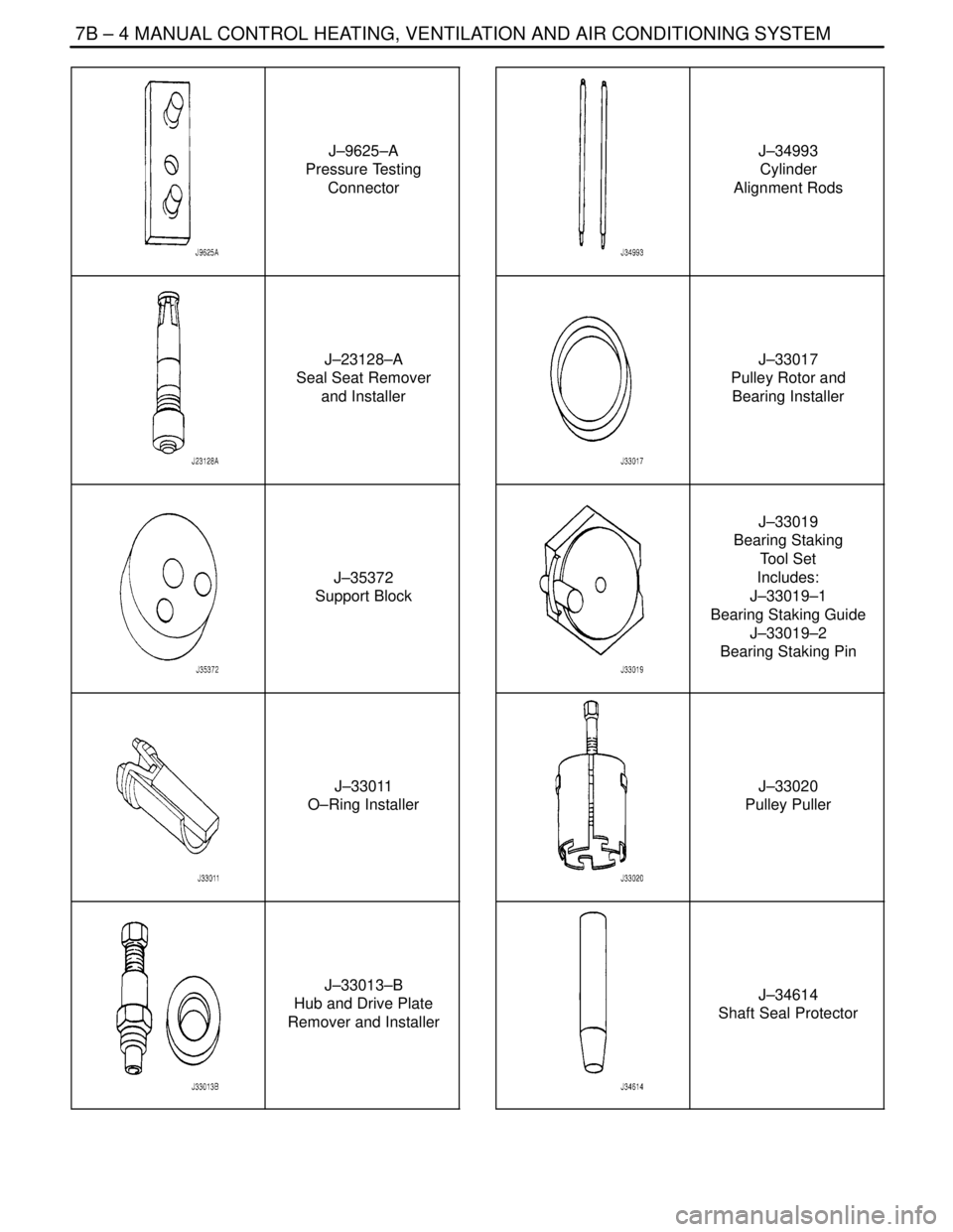
J–9625–A
Pressure Testing
Connector
J–23128–A
Seal Seat Remover
and Installer
J–35372
Support Block
J–33011
O–Ring Installer
J–33013–B
Hub and Drive Plate
Remover and Installer
J–34993
Cylinder
Alignment Rods
J–33017
Pulley Rotor and
Bearing Installer
J–33019
Bearing Staking
Tool Set
Includes:
J–33019–1
Bearing Staking Guide
J–33019–2
Bearing Staking Pin
J–33020
Pulley Puller
J–34614
Shaft Seal Protector
Page 2021 of 2643

MANUAL CONTROL HEATING, VENTILATION AND AIR CONDITIONING SYSTEM 7B – 19
DAEWOO V–121 BL4
MAINTENANCE AND REPAIR
ON–VEHICLE SERVICE
GENERAL A/C SYSTEM SERVICE PROCEDURES
O–RING REPLACEMENT
Important : Even though O–rings may look identical, it is
extremely important that only recommended service re-
placement air conditioning O–rings be used or excessive
leakage of refrigerant may occur.
Important : Always slip the O–ring onto the flange tube to
ensure proper locating and sealing.
Install new Daewoo–approved service replacement air
conditioning (A/C) O–rings whenever a joint or a fitting is
disassembled, except when the O–rings are provided on
new components.
When replacing O–rings on an A/C component or a joint
connection, the fitting design should be identified to en-
sure installation of the correct air conditioning service re-
placement O–ring. Some joint connections and compo-
nents will implement a ”captured” O–ring design fitting that
uses a groove to retain the O–ring. Others do not have a
groove and use a ”non–captured” or ”standard” O–ring.
Assembly and tightening procedures are the same for
both designs, but the O–rings are different.
Notice : Before installation, verify that both O–rings and
fittings have not been nicked or deformed. Deformed or
nicked parts must be replaced. Failure to use the proper
service replacement parts and procedures may result in
excessive refrigerant leakage.
HANDLING REFRIGERANT
CAUTION : Always work in a well–ventilated area and
avoid breathing any refrigerant fumes. If you have dif-
ficulty with breathing, seek medical attention immedi-
ately. If refrigerant comes in contact with any part of
your body, flush the exposed area with water. If a rash
or pain develops, seek medical attention.
Air conditioning systems contain refrigerant. This is a
chemical mixture which requires special handling proce-
dures to avoid personal injury.
Always wear goggles and wrap a clean cloth around the
fittings, the valves and the connections when performing
work that involves opening the refrigerant system. Do not
weld or steam clean on or near any vehicle–installed air
conditioning lines or components.
All refrigerant drums are shipped with a heavy metal screw
cap. The purpose of the cap is to protect the valve and the
safety plug from damage. It is good practice to replace the
cap after each use of the drum.If it is necessary to transport or carry any container of re-
frigerant in a vehicle, do not carry it in the passenger
compartment.
HANDLING OF REFRIGERANT LINES
AND FITTINGS
Notice : Using too low or too high torque when tightening
a fitting can result in loose joints or deformed joint parts.
Both conditions can result in refrigerant leakage.
S Keep all metal tubing lines free of dents or kinks.
Any line restrictions will cause the loss of system
capacity.
S Never bend a flexible hose line to a radius of less
than four times the diameter of the hose.
S Never allow a flexible hose line to come within 65
mm (2–1/2 inches) of the exhaust manifold.
S Inspect flexible hose lines regularly for leaks or
brittleness.
S Replace flexible hose lines with new lines if you find
signs of deterioration or leaking.
S Discharge all refrigerant of the refrigeration system
before disconnecting any fitting in the refrigeration
system.
S Proceed very cautiously regardless of the gauge
readings.
CAUTION : Keep your face and your hands away from
the fitting so that you will not be injured if there hap-
pens to be liquid refrigerant in the line.
S Open the fittings very slowly.
S If you notice pressure when you loosen a fitting,
allow the pressure to bleed off as described under
”Discharging, Adding Oil, Evacuating, and Charging
Procedures for A/C System” in this section.
S Cap or tape any refrigerant line immediately after it
is opened. This will prevent the entrance of mois-
ture and dirt, which can cause internal compressor
wear or plugged lines in the condenser, the evapo-
rator core, the expansion valve, or the compressor
inlet screens.
Important : Use two proper wrenches to connect the O–
ring fittings.
S Back up the opposing fitting to prevent distortion of
the connecting lines or the components.
S Back up both the swagged fitting on the flexible
hose connections and the coupling to which it is
attached with two wrenches to prevent turning the
fitting and damaging the ground seat.
S Keep the O–rings and the seats in perfect condi-
tion. A burr or a piece of dirt may cause a refriger-
ant leak.