Page 182 of 578

3 - 10
INSP
ADJOIL PRESSURE INSPECTION/PILOT AIR SCREW
ADJUSTMENT/ENGINE IDLING SPEED ADJUSTMENT
OIL PRESSURE INSPECTION
1. Check:
�Oil pressure
Checking steps:
�Slightly loosen the oil pressure check bolt
1.
�Start the engine and keep it idling until oil
starts to seep from the oil pressure check
bolt. If no oil comes out after one minute,
turn the engine off so it will not seize.
�Check oil passages and oil pump for dam-
age or leakage.
�Start the engine after solving the prob-
lem(s) and recheck the oil pressure.
�Tighten the oil pressure check bolt.
T R..
Oil pressure check bolt:
7 Nm (0.7 m • kg, 5.1 ft • lb)
PILOT AIR SCREW ADJUSTMENT
1. Adjust:
�Pilot air screw 1
Adjustment steps:
NOTE:
To optimize the fuel flow at a smaller throttle
opening, each machine’s pilot air screw has
been individually set at the factory. Before
adjusting the pilot air screw, turn it in fully
and count the number of turns. Record this
number as the factory-set number of turns
out.
�Screw in the pilot air screw until it is lightly
seated.
�Back out by the specified number of turns.
Pilot air screw:
2-1/2 ~ 3-1/2 turns out (example)
ENGINE IDLING SPEED ADJUSTMENT
1. Start the engine and thoroughly warm it
up.
2. Attach:
�Inductive tachometer
To spark plug lead.
3. Adjust:
�Engine idling speed
Page 184 of 578
3 - 11
INSP
ADJ
VALVE CLEARANCE INSPECTION AND ADJUSTMENT
VALVE CLEARANCE INSPECTION AND
ADJUSTMENT
NOTE:
�The valve clearance should be adjusted
when the engine is cool to the touch.
�The piston must be at Top Dead Center
(T.D.C.) on compression stroke to check or
adjust the valve clearance.
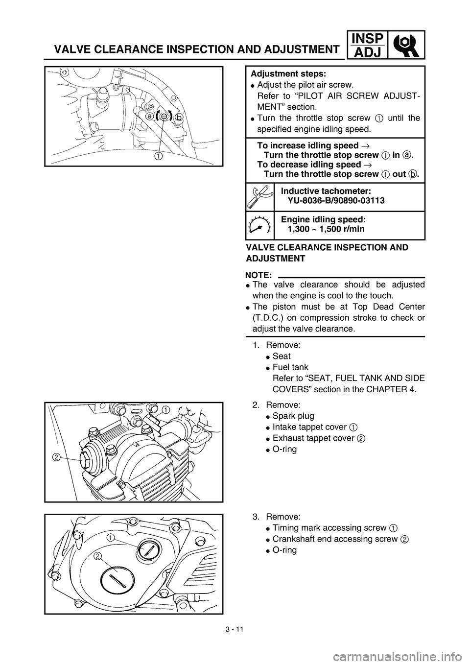
1. Remove:
�Seat
�Fuel tank
Refer to “SEAT, FUEL TANK AND SIDE
COVERS” section in the CHAPTER 4. Adjustment steps:
�Adjust the pilot air screw.
Refer to “PILOT AIR SCREW ADJUST-
MENT” section.
�Turn the throttle stop screw 1 until the
specified engine idling speed.
To increase idling speed →
Turn the throttle stop screw 1 in a.
To decrease idling speed →
Turn the throttle stop screw 1 out b.
Inductive tachometer:
YU-8036-B/90890-03113
Engine idling speed:
1,300 ~ 1,500 r/min
2. Remove:
�Spark plug
�Intake tappet cover 1
�Exhaust tappet cover 2
�O-ring
3. Remove:
�Timing mark accessing screw 1
�Crankshaft end accessing screw 2
�O-ring
Page 190 of 578
3 - 14
INSP
ADJ
SPARK ARRESTER CLEANING (For USA)
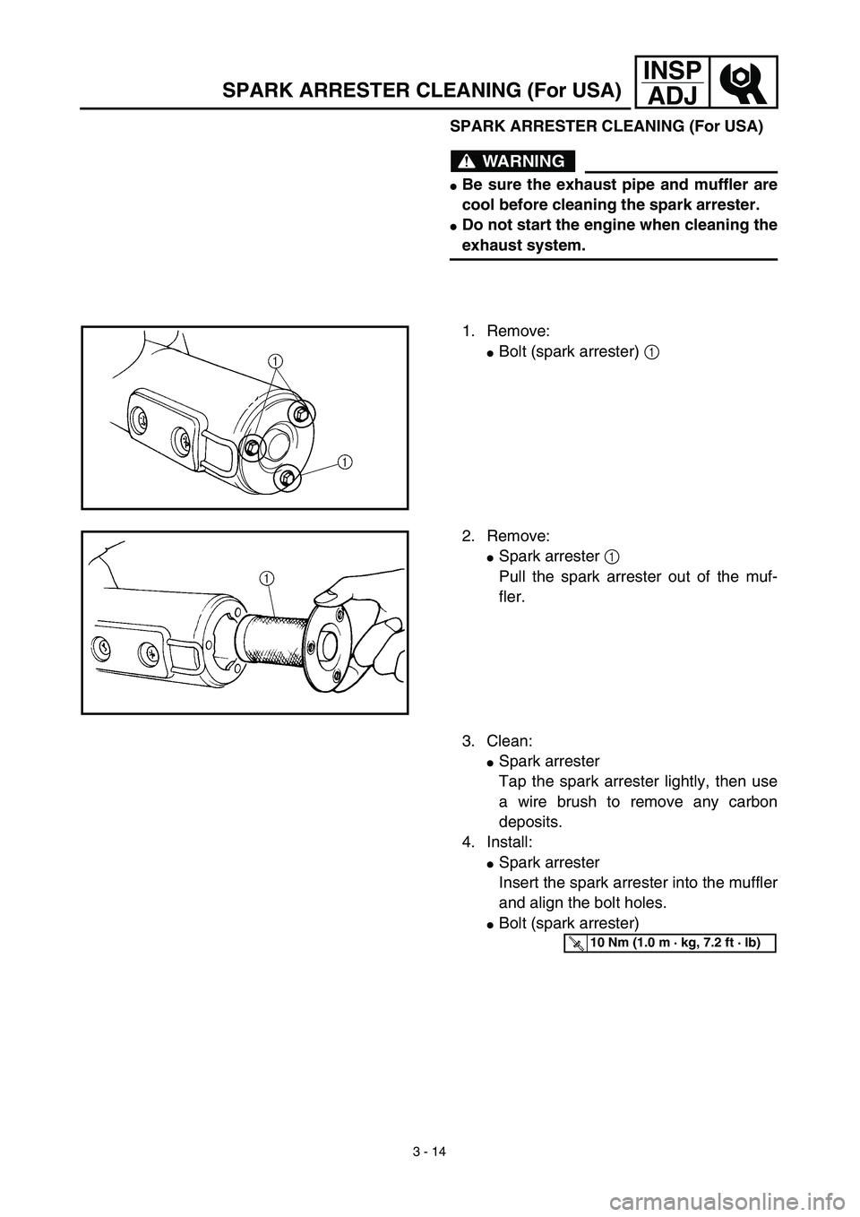
SPARK ARRESTER CLEANING (For USA)
WARNING
�Be sure the exhaust pipe and muffler are
cool before cleaning the spark arrester.
�Do not start the engine when cleaning the
exhaust system.
1. Remove:
�Bolt (spark arrester) 1
2. Remove:
�Spark arrester 1
Pull the spark arrester out of the muf-
fler.
3. Clean:
�Spark arrester
Tap the spark arrester lightly, then use
a wire brush to remove any carbon
deposits.
4. Install:
�Spark arrester
Insert the spark arrester into the muffler
and align the bolt holes.
�Bolt (spark arrester)
T R..10 Nm (1.0 m · kg, 7.2 ft · lb)
Page 206 of 578

3 - 22
INSP
ADJ
DRIVE CHAIN SLACK ADJUSTMENT
6. Lubricate:
�Drive chain
Drive chain lubricant:
SAE 10W-30 motor oil or suit-
able chain lubricants
DRIVE CHAIN SLACK ADJUSTMENT
1. Elevate the rear wheel by placing the
suitable stand under the engine.
2. Check:
�Drive chain slack a
In the center between the drive axle
and rear wheel axle.
Out of specification → Adjust.
NOTE:
Before checking and/or adjusting, rotate the
rear wheel through several revolutions and
check the slack several times to find the tight-
est point. Check and/or adjust chain slack with
rear wheel in this “tight chain” position.
Drive chain slack:
35 ~ 50 mm (1.4 ~ 2.0 in)
3. Adjust:
�Drive chain slack
Drive chain slack adjustment steps:
�Loosen the axle nut 1.
�Turn both drive chain pullers 2 the same
amount a and adjust them to the stopper
in the same position so that the drive chain
slack is within the specified limits.
CAUTION:
Too small chain slack will overload the
engine and other vital parts; keep the
slack within the specified limits.
�Tighten the axle nut while pushing down
the drive chain.
T R..
Axle nut:
60 Nm (6.0 m • kg, 43 ft • lb)
Page 210 of 578

3 - 24
INSP
ADJ
REAR SHOCK ABSORBER ASSEMBLY
INSPECTION
1. Inspect:
�Swingarm smooth action
Abnormal noise/unsmooth action →
Grease the pivoting points or repair the
pivoting points.
Damage/oil leakage → Replace.
REAR SHOCK ABSORBER SPRING
PRELOAD ADJUSTMENT
1. Elevate the rear wheel by placing the
suitable stand under the engine.
2. Remove:
�Left side cover
3. Loosen:
�Locknut 1
4. Adjust:
�Spring preload
By turning the adjuster 2.
NOTE:
�Be sure to remove all dirt and mud from
around the locknut and adjuster before
adjustment.
�The length of the spring (installed) changes
1.5 mm (0.06 in) per turn of the adjuster.
CAUTION:
Never attempt to turn the adjuster beyond
the maximum or minimum setting.Stiffer →Increase the spring preload.
(Turn the adjuster 2 in.)
Softer →Decrease the spring preload.
(Turn the adjuster 2 out.)
Spring length (installed) a:
Standard length Extent of adjustment
TT-R125E:
165 mm
(6.50 in)
TT-R125LWE:
160.5 mm
(6.32 in)TT-R125E:
155 ~ 175 mm
(6.10 ~ 6.89 in)
TT-R125LWE:
147.5 ~ 167.5 mm
(5.81 ~ 6.59 in)
REAR SHOCK ABSORBER ASSEMBLY INSPECTION/
REAR SHOCK ABSORBER SPRING PRELOAD ADJUSTMENT
Page 218 of 578
3 - 28
INSP
ADJ
STEERING HEAD INSPECTION AND ADJUSTMENT
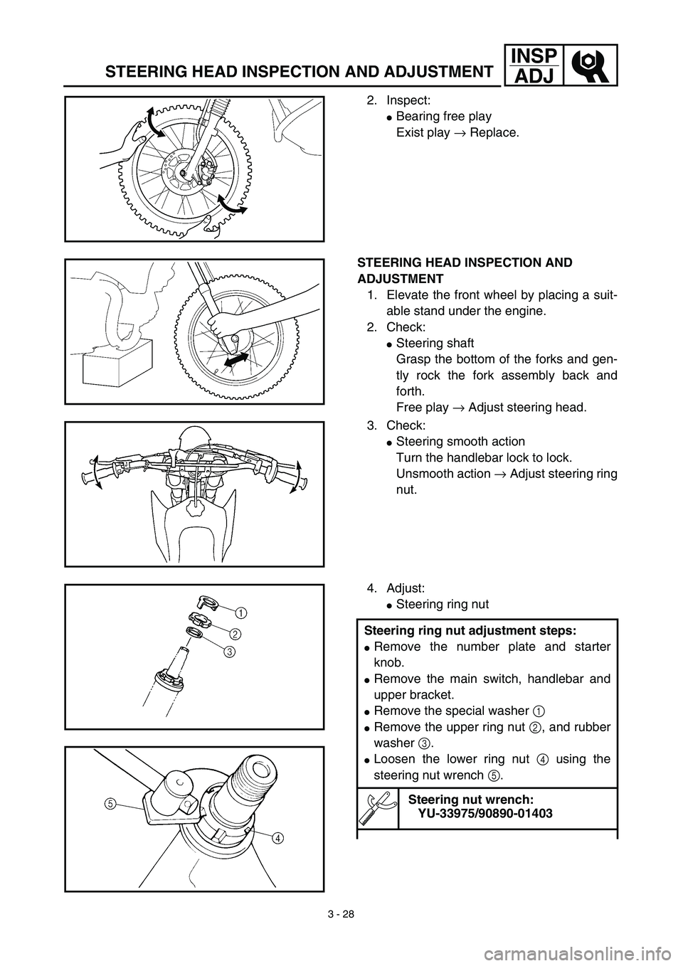
2. Inspect:
�Bearing free play
Exist play → Replace.
STEERING HEAD INSPECTION AND
ADJUSTMENT
1. Elevate the front wheel by placing a suit-
able stand under the engine.
2. Check:
�Steering shaft
Grasp the bottom of the forks and gen-
tly rock the fork assembly back and
forth.
Free play → Adjust steering head.
3. Check:
�Steering smooth action
Turn the handlebar lock to lock.
Unsmooth action → Adjust steering ring
nut.
4. Adjust:
�Steering ring nut
Steering ring nut adjustment steps:
�Remove the number plate and starter
knob.
�Remove the main switch, handlebar and
upper bracket.
�Remove the special washer 1
�Remove the upper ring nut 2, and rubber
washer 3.
�Loosen the lower ring nut 4 using the
steering nut wrench 5.
Steering nut wrench:
YU-33975/90890-01403
Page 226 of 578
3 - 32
INSP
ADJ
ELECTRICAL/SPARK PLUG INSPECTION
EC370000
ELECTRICAL
EC371001
SPARK PLUG INSPECTION
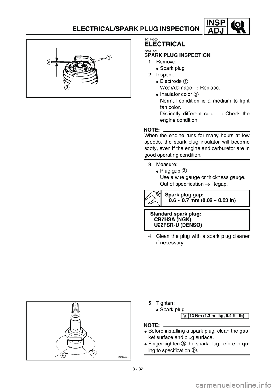
1. Remove:
�Spark plug
2. Inspect:
�Electrode 1
Wear/damage → Replace.
�Insulator color 2
Normal condition is a medium to light
tan color.
Distinctly different color → Check the
engine condition.
NOTE:
When the engine runs for many hours at low
speeds, the spark plug insulator will become
sooty, even if the engine and carburetor are in
good operating condition.
3. Measure:
�Plug gap a
Use a wire gauge or thickness gauge.
Out of specification → Regap.
4. Clean the plug with a spark plug cleaner
if necessary.
Spark plug gap:
0.6 ~ 0.7 mm (0.02 ~ 0.03 in)
Standard spark plug:
CR7HSA (NGK)
U22FSR-U (DENSO)
5. Tighten:
�Spark plug
NOTE:
�Before installing a spark plug, clean the gas-
ket surface and plug surface.
�Finger-tighten a the spark plug before torqu-
ing to specification b.
T R..13 Nm (1.3 m · kg, 9.4 ft · lb)
Page 246 of 578
4 - 1
ENG
EC400000
ENGINE
EC4R0000
SEAT, FUEL TANK AND SIDE COVERS
Extent of removal:
1
Seat removal
2
Fuel tank removal
3
Side covers removal
4
Number plate removal
Extent of removal Order Part name Q’ty Remarks
Preparation for removal
SEAT, FUEL TANK AND SIDE
COVERS REMOVAL
Turn the fuel cock to “OFF”.
1 Seat 1
2 Air scoop (left and right) 2
3 Fuel hose 1 Remove on fuel tank side.
4 Fitting band 1
5 Bolt (fuel tank) 2
6 Fuel tank 1
7 Left side cover 1
8 Right side cover 1
9Number plate
1
13
4
2
3
SEAT, FUEL TANK AND SIDE COVERS