Page 538 of 578
–+ELEC
6 - 2
IGNITION SYSTEM
EC620000
IGNITION SYSTEM
INSPECTION STEPS
Use the following steps for checking the possibility of the malfunctioning engine being attributable to
ignition system failure and for checking the spark plug which will not spark.
*marked: Only when the ignition checker is used.
NOTE:
�
Remove the following parts before inspection.
1) Seat
2) Fuel tank
�
Use the following special tools in this inspection.
Dynamic spark tester:
YM-34487
Ignition checker:
90890-06754
Pocket tester:
YU-3112-C/90890-03112
Spark gap test*Clean or replace
spark plug.
Check entire ignition
system for connection.Repair or replace.
Check main switch. Replace.
Check engine stop switch. Replace.
Check ignition coil. Primary coil Replace.
Secondary coil Replace.
Check CDI magneto. Pickup coil Replace.
Source coil Replace.
Replace CDI unit.
No Spark
OK
OK
OK
OK
Spark
No good
No good
No good
No good
No good
No good
OK
No good
Page 542 of 578
6 - 3
–+ELEC
IGNITION SYSTEM
EC622001
SPARK GAP TEST
1. Disconnect the spark plug cap from spark
plug.
2. Connect the dynamic spark tester
1
(ignition checker
2
) as shown.
�
Spark plug cap
3
�
Spark plug
4
Å
For USA and CDN
ı
Except for USA and CDN
3. Kick the kick starter.
4. Check the ignition spark gap.
5. Start engine, and increase spark gap until
misfire occurs. (for USA and CDN only)
Minimum spark gap:
6.0 mm (0.24 in)
Å
ı
EC624000
COUPLERS AND LEADS CONNECTION
INSPECTION
1. Check:
�
Couplers and leads connection
Rust/dust/looseness/short-circuit
→
Repair or replace.
MAIN SWITCH INSPECTION
1. Inspect:
�
Main switch continuity
Check for continuity as follows:
Incorrect continuity
→
Replace.
Tester (+)
→
Red lead
1
Tester (–)
→
Brown lead
2
Continuous
Tester (+)
→
Black/White lead
3
Tester (–)
→
Black lead
4
Continuous
R
1
Br
2
B/W
3
B
4Tester selec-
tor position
ON
Ω × 1
OFF
RB/W
BrB
13
24
Page 544 of 578
6 - 4
–+ELECIGNITION SYSTEM
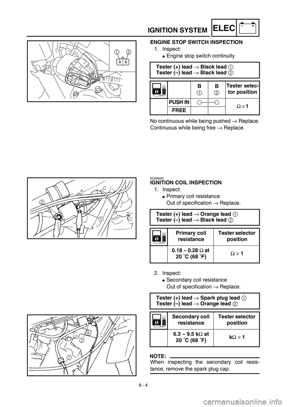
ENGINE STOP SWITCH INSPECTION
1. Inspect:
�Engine stop switch continuity
No continuous while being pushed → Replace.
Continuous while being free → Replace. Tester (+) lead → Black lead 1
Tester (–) lead → Black lead 2
B
1B
2Tester selec-
tor position
PUSH IN
Ω × 1
FREE
BB
1
2
EC626002
IGNITION COIL INSPECTION
1. Inspect:
�Primary coil resistance
Out of specification → Replace.
2. Inspect:
�Secondary coil resistance
Out of specification → Replace.
NOTE:
When inspecting the secondary coil resis-
tance, remove the spark plug cap.Tester (+) lead → Orange lead 1
Tester (–) lead → Black lead 2
Primary coil
resistanceTester selector
position
0.18 ~ 0.28 Ω at
20 ˚C (68 ˚F)Ω × 1
Tester (+) lead → Spark plug lead 1
Tester (–) lead → Orange lead 2
Secondary coil
resistanceTester selector
position
6.3 ~ 9.5 kΩ at
20 ˚C (68 ˚F)kΩ × 1
Page 548 of 578

6 - 6
–+ELEC
ELECTRIC STARTING SYSTEM
STARTING CIRCUIT CUT-OFF SYSTEM
OPERATION
If the main switch is set to “ON”, the starter
motor can only operate if at least one of the
following conditions is met:
�The transmission is in neutral (the neutral
switch is closed).
�The clutch lever is pulled to the handlebar
(the clutch switch is closed).
The starting circuit cut-off relay prevents the
starter motor from operating when neither of
these conditions has been met. In this
instance, the starting circuit cut-off relay is
open so current cannot reach the starter
motor. When at least one of the above condi-
tions has been met the starting circuit cut-off
relay is closed and the engine can be started
by pressing the start switch.
WHEN THE TRANSMISSION IS
IN NEUTRAL
WHEN THE CLUTCH LEVER IS
PULLED TO THE HANDLEBAR
1Battery
2Main fuse
3Main switch
4Start switch
5Starting circuit cut-off relay
6Neutral switch
7Clutch switch
8Starter relay
9Starter motor
12
M
3
8
54
6 9
7
ELECTRIC STARTING SYSTEM
Page 560 of 578
6 - 11
–+ELEC
STARTER MOTOR
7
4
3
52
1
5 8
0
90
95
6
1
New
New
New
Extent of removal:1 Starter motor disassembly
Extent of removal Order Part name Q’ty Remarks
STARTER MOTOR REMOVAL
Preparation for removal Drain the engine oil. Refer to “ENGINE OIL REPLACEMENT”
section in the CHAPTER 3.
1 Starter motor 1
STARTER MOTOR DISASSEM-
BLY
1Starter motor front cover 1
2Washer (starter motor front
cover)1
3Plain washer 1
4Circlip 1
5O-ring
3
1
ELECTRIC STARTING SYSTEM
Page 570 of 578
–+ELEC
6 - 16
CHARGING SYSTEM
EC680000
CHARGING SYSTEM
EC681001
INSPECTION STEPS
If the battery is not charged, use the following inspection steps.
*1 marked: Refer to “FUSE INSPECTION” section in the CHAPTER 3.
*2 marked: Refer to “BATTERY INSPECTION AND CHARGING” section in the CHAPTER 3.
NOTE:
�Remove the following parts before inspection.
1) Seat
2) Rear fender
3) Fuel tank
�Use the following special tool in this inspection.
Pocket tester:
YU-3112-C/90890-03112Inductive tachometer:
YU-8036-B
Engine tachometer:
90890-03113
*1 Check fuse.Replace fuse and
check wire harness.
*2 Check battery. Recharge or replace.
Check each coupler and
wire connection.Repair or replace.
Check charging voltage.Charging system is
good.
Check CDI magneto. Charging coil Replace.
Replace rectifier/regulator.
OK
OK
OK
No good
OK
No good
No good
No good
No good
OK
Page 574 of 578
6 - 17
–+ELECCHARGING SYSTEM
EC624000
COUPLERS AND LEADS CONNECTION
INSPECTION
1. Check:
�Couplers and leads connection
Rust/dust/looseness/short-circuit →
Repair or replace.
CHARGING VOLTAGE INSPECTION
1. Start the engine.
2. Inspect:
�Charging voltage
Out of specification → If no failure is
found in checking the source coil resis-
tance, replace the rectifier/regulator.
Tester (+) lead → Red lead 1
Tester (–) lead → Black lead 2
Charging
voltageTester selector
position
14.0 ~ 15.0 V at
5,000 r/minDCV-20
W
B
RY
2
1
3. Inspect:
�Charging coil resistance
Out of specification → Replace.
Tester (+) lead → White lead 1
Tester (–) lead → Black lead 2
Charging coil
resistanceTester selector
position
0.64 ~ 0.96 Ω at
20 ˚C (68 ˚F)Ω × 1
WSb
YB
1
2