Page 222 of 578
3 - 30
INSP
ADJ
STEERING HEAD INSPECTION AND ADJUSTMENT
CAUTION:
First tighten the bolts on the front side of
the handlebar holder, and then tighten
the bolts on the rear side.
T R..
Pinch bolt (upper bracket):
25 Nm (2.5 m • kg, 18 ft • lb)
Steering stem nut:
110 Nm (11.0 m • kg, 80 ft • lb)
Handlebar upper holder:
23 Nm (2.3 m • kg, 17 ft • lb)
Starter knob nut:
1 Nm (0.1 m • kg, 0.7 ft • lb)
Number plate:
7 Nm (0.7 m • kg, 5.1 ft • lb)
Page 274 of 578
4 - 15
ENGCYLINDER HEAD
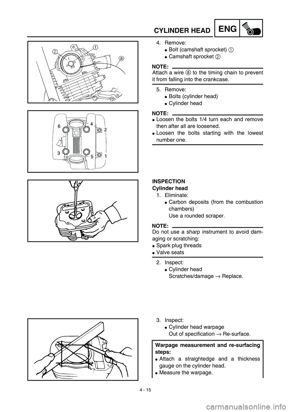
4. Remove:
�Bolt (camshaft sprocket) 1
�Camshaft sprocket 2
NOTE:
Attach a wire a to the timing chain to prevent
it from falling into the crankcase.
5. Remove:
�Bolts (cylinder head)
�Cylinder head
NOTE:
�Loosen the bolts 1/4 turn each and remove
then after all are loosened.
�Loosen the bolts starting with the lowest
number one.
INSPECTION
Cylinder head
1. Eliminate:
�Carbon deposits (from the combustion
chambers)
Use a rounded scraper.
NOTE:
Do not use a sharp instrument to avoid dam-
aging or scratching:
�Spark plug threads
�Valve seats
2. Inspect:
�Cylinder head
Scratches/damage → Replace.
3. Inspect:
�Cylinder head warpage
Out of specification → Re-surface.
Warpage measurement and re-surfacing
steps:
�Attach a straightedge and a thickness
gauge on the cylinder head.
�Measure the warpage.
Page 276 of 578
4 - 16
ENGCYLINDER HEAD
Warpage limit:
0.03 mm (0.0012 in)
�If the warpage is out of specification,
resurface the cylinder head.
�Place #400 ~ 600 grit wet sandpaper on
the surface plate, and re-surface the head
using a figure-eight sanding pattern.
NOTE:
Rotate the cylinder head several times to
avoid removing too much material from one
side.
ASSEMBLY AND INSTALLATION
Cylinder head
1. Install:
�Dowel pin 1
�Gasket 2 New
2. Install:
�Cylinder head
�Copper washer
�Bolt (cylinder head)
NOTE:
�Apply Quick gasket® (YAMAHA Bond
No.1215) on end of the cylinder head bolts
(M6), as shown.
�Apply the engine oil on the contact surfaces of
the bolts (cylinder head) and copper washers.
�Follow the numerical order shown in the illus-
tration. Tighten the bolts in two stages.
Quick gasket®:
ACC-QUICK-GS-KT
YAMAHA Bond No.1215:
90890-85505
T R..M8 22 Nm (2.2 m · kg, 16 ft · lb)
M6 10 Nm (1.0 m · kg, 7.2 ft · lb)
Page 280 of 578
4 - 18
ENGCYLINDER HEAD
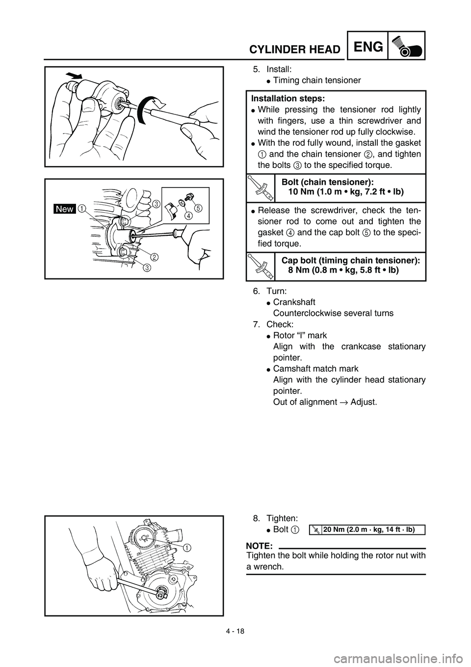
5. Install:
�Timing chain tensioner
6. Turn:
�Crankshaft
Counterclockwise several turns
7. Check:
�Rotor “I” mark
Align with the crankcase stationary
pointer.
�Camshaft match mark
Align with the cylinder head stationary
pointer.
Out of alignment → Adjust. Installation steps:
�While pressing the tensioner rod lightly
with fingers, use a thin screwdriver and
wind the tensioner rod up fully clockwise.
�With the rod fully wound, install the gasket
1 and the chain tensioner 2, and tighten
the bolts 3 to the specified torque.
T R..
Bolt (chain tensioner):
10 Nm (1.0 m • kg, 7.2 ft • lb)
�Release the screwdriver, check the ten-
sioner rod to come out and tighten the
gasket 4 and the cap bolt 5 to the speci-
fied torque.
T R..
Cap bolt (timing chain tensioner):
8 Nm (0.8 m • kg, 5.8 ft • lb)
8. Tighten:
�Bolt 1
NOTE:
Tighten the bolt while holding the rotor nut with
a wrench.
T R..20 Nm (2.0 m · kg, 14 ft · lb)
Page 508 of 578
5 - 52
CHAS
4. Install:
�Lower bracket 1
NOTE:
Apply the lithium soap base grease on the
bearing.
5. Install:
�Lower ring nut 1
�Rubber washer
�Upper ring nut
�Special washer
Tighten the ring nut using the steering
nut wrench 2.
NOTE:
Install the lower ring nut with its larger cham-
fered portion a facing downward.
Refer to “STEERING HEAD INSPEC-
TION AND ADJUSTMENT” section in
the CHAPTER 3.
6. Check the steering shaft by turning it lock
to lock. If there is any binding, remove the
steering shaft assembly and inspect the
steering bearings.
T R..20 Nm (2.0 m · kg, 14 ft · lb)
7. Install:
�Upper bracket 1
�Steering stem nut 2
�Starter knob bracket 3
NOTE:
Do not tighten the steering stem nut yet.
T R..10 Nm (1.0 m · kg, 7.2 ft · lb)
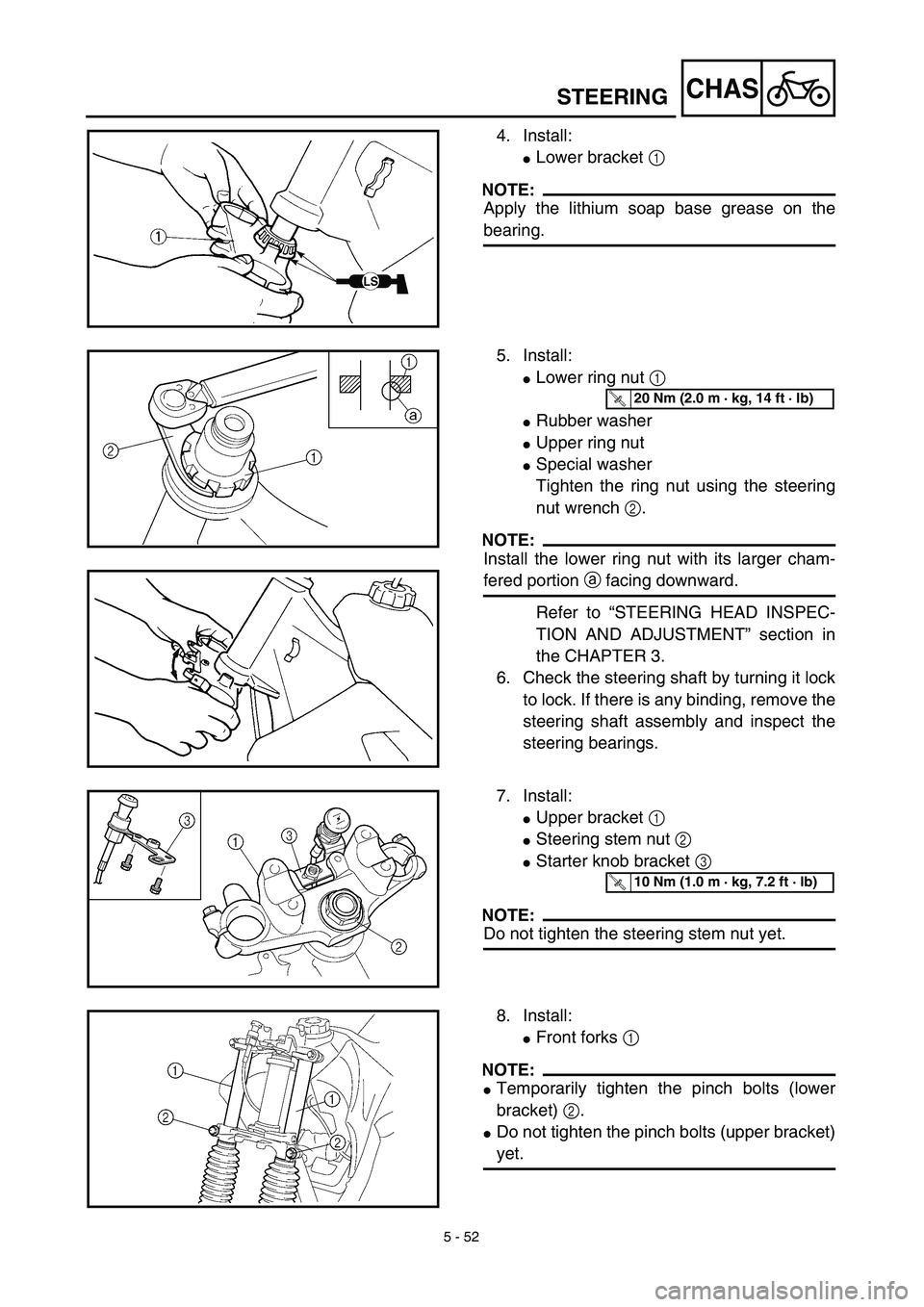
8. Install:
�Front forks 1
NOTE:
�Temporarily tighten the pinch bolts (lower
bracket) 2.
�Do not tighten the pinch bolts (upper bracket)
yet.
STEERING