Page 394 of 578
4 - 75
ENGTRANSMISSION, SHIFT CAM AND SHIFT FORK
TRANSMISSION, SHIFT CAM AND SHIFT FORK
Extent of removal:1 Shift cam and shift fork removal2 Main axle and drive axle removal
Extent of removal Order Part name Q’ty Remarks
TRANSMISSION, SHIFTCAM
AND SHIFT FORK REMOVAL
Preparation for removal Engine Refer to “ENGINE REMOVAL” section.
Separate the crankcase. Refer to “CRANKCASE, CRANKSHAFT
AND BALANCER” section.
1 Shift fork guide bar 1 (short) 1
2 Shift fork guide bar 2 (long) 1
3 Shift cam 1
4 Shift fork 2 (C) 1
5 Shift fork 3 (R) 1
6 Shift fork 1 (L) 1
7 Main axle 1
Refer to “REMOVAL POINTS”.
8 Drive axle 1
9 Push rod 2 1
10 Washer 1
1
2
Page 402 of 578
4 - 79
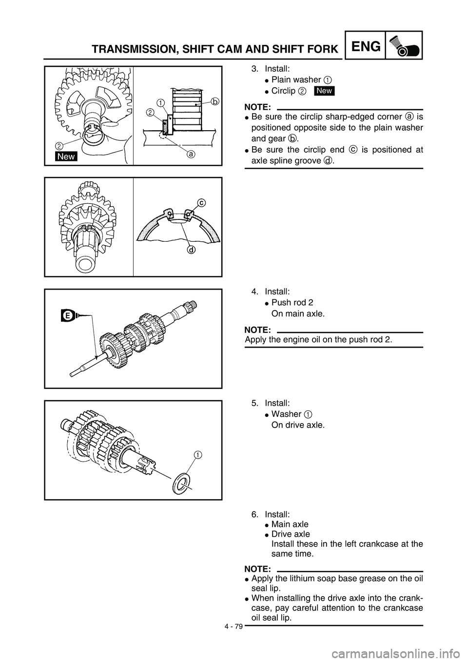
ENGTRANSMISSION, SHIFT CAM AND SHIFT FORK
3. Install:
�Plain washer 1
�Circlip 2
NOTE:
�Be sure the circlip sharp-edged corner a is
positioned opposite side to the plain washer
and gear b.
�Be sure the circlip end c is positioned at
axle spline groove d.
New
4. Install:
�Push rod 2
On main axle.
NOTE:
Apply the engine oil on the push rod 2.
5. Install:
�Washer 1
On drive axle.
6. Install:
�Main axle
�Drive axle
Install these in the left crankcase at the
same time.
NOTE:
�Apply the lithium soap base grease on the oil
seal lip.
�When installing the drive axle into the crank-
case, pay careful attention to the crankcase
oil seal lip.
Page 404 of 578
4 - 80
ENGTRANSMISSION, SHIFT CAM AND SHIFT FORK
Shift cam and shift fork
1. Install:
�Shift fork 1 (L) 1
�Shift fork 2 (C) 2
�Shift fork 3 (R) 3
NOTE:
�Mesh the shift fork #1 (L) with the 2nd wheel
gear and #3 (R) with the 4th wheel gear on
the drive axle.
�Mesh the shift fork #2 (C) with the 3rd pinion
gear on the main axle.
2. Install:
�Shift cam 1
NOTE:
Apply the engine oil on the shift cam.
3. Install:
�Shift fork guide bar 1 (short) 1
�Shift fork guide bar 2 (long) 2
NOTE:
�Apply the engine oil on the guide bars.
�Be sure the long bar is inserted into the shift
forks #1 and #3 and the short one into #2.
4. Check:
�Shifter operation
�Transmission operation
Unsmooth operation → Repair.
Page 406 of 578
5 - 1
CHAS
FRONT WHEEL AND FRONT BRAKE (TT-R125E)
EC500000
CHASSIS
FRONT WHEEL AND FRONT BRAKE (TT-R125E)
Extent of removal:
1
Front wheel removal
2
Wheel bearing removal
3
Brake shoe plate assembly removal and disassembly
Extent of removal Order Part name Q’ty Remarks
Preparation for removal
FRONT WHEEL AND DRUM
BRAKE
Hold the machine by placing the
suitable stand under the engine.
WARNING
Support the machine securely so there is no
danger of it falling over.
1 Brake cable holder 1
2 Brake cable 1 Disconnect at the lever side, first.
3 Axle nut 1
4 Wheel axle 1
5 Front wheel 1
6 Collar set 1
7 Brake shoe plate assembly 1
8 Oil seal 1
9 Wheel bearing 2 Refer to “REMOVAL POINTS”.
10Spacer
1
2
3
1
Page 420 of 578
5 - 8
CHAS
FRONT WHEEL (TT-R125LWE)
Extent of removal:1 Front wheel removal2 Wheel bearing removal
3 Brake disc removal
Extent of removal Order Part name Q’ty Remarks
Preparation for removalFRONT WHEEL REMOVAL
Hold the machine by placing the
suitable stand under the engine.
WARNING
Support the machine securely so there is nodanger of it falling over.
1 Axle nut 1
2 Washer 1
3 Wheel axle 1
4 Front wheel 1
5 Collar 2
6 Oil seal 2
7 Wheel bearing 2 Refer to “REMOVAL POINTS”.
8 Spacer 1
9Brake disk
1
2
31
3
FRONT WHEEL (TT-R125LWE)
Page 428 of 578
5 - 12
CHAS
FRONT BRAKE (TT-R125LWE)
Extent of removal:1 Brake hose removal 2 Brake caliper removal
3 Brake master cylinder removal
Extent of removal Order Part name Q’ty Remarks
Preparation for removalFRONT BRAKE REMOVAL
Hold the machine by placing the
suitable stand under the engine.
Drain the brake fluid.
WARNING
Support the machine securely so there is nodanger of it falling over.
Refer to “REMOVAL POINTS”.
1 Brake hose holder 2
2 Union bolt 1
3 Brake hose 1
4 Joint 1
5 Brake caliper support bolt 1
6 Brake caliper 1 Refer to “REMOVAL POINTS”.
7 Brake lever 1
8 Brake master cylinder bracket 1
9Brake master cylinder
1
3
12
2
3
FRONT BRAKE (TT-R125LWE)
Page 430 of 578
5 - 13
CHASFRONT BRAKE (TT-R125LWE)
BRAKE CALIPER AND BRAKE MASTER CYLINDER DISASSEMBLY
Extent of removal:1 Brake caliper disassembly2 Brake master cylinder disassembly
Extent of removal Order Part name Q’ty Remarks
Preparation for removalBRAKE CALIPER AND BRAKE
MASTER CYLINDER DISAS-
SEMBLY
Hold the machine by placing the
suitable stand under the engine.
WARNING
Support the machine securely so there is no
danger of it falling over.
1Brake pad 2
2Brake caliper bracket 1
3Brake caliper piston 2
Refer to “REMOVAL POINTS”. 4Brake caliper dust seal 2
5Brake caliper piston seal 2
6Pin boot 1
7Sleeve boot 1
8Brake master cylinder cap 1
9Diaphragm 1
0Brake master cylinder boot 1
ACirclip 1
BWasher 1
CBrake master cylinder kit 1
2
1
Page 452 of 578
5 - 24
CHAS
REAR WHEEL AND REAR BRAKE
Extent of removal:1 Rear wheel removal 2 Wheel bearing removal
3 Brake shoe plate assembly removal and disassembly
Extent of removal Order Part name Q’ty Remarks
Preparation for removalREAR WHEEL AND DRUM
BRAKE
Hold the machine by placing the
suitable stand under the engine.
WARNING
Support the machine securely so there is nodanger of it falling over.
1 Brake rod 1
2 Axle nut 1
3 Drive chain puller (right) 1
4 Wheel axle 1
5 Drive chain puller (left) 1
6 Drive chain 1
7 Rear wheel 1 Refer to “REMOVAL POINTS”.
8 Collar (right) 1
9 Brake shoe plate assembly 1
10Collar (left)
1
231
REAR WHEEL AND REAR BRAKE


EC500000
CHASSIS
FRONT WHEEL AND FRONT BRAKE (TT-R125E)
Extent of removal:
1
Front wheel removal
2
Wheel bearing removal
3
Brak")

Extent of removal:1 Front wheel removal2 Wheel bearing removal
3 Brake disc removal
Extent of removal Order Part name Q’ty Remarks
Preparation for removalFRONT WH")

Extent of removal:1 Brake hose removal 2 Brake caliper removal
3 Brake master cylinder removal
Extent of removal Order Part name Q’ty Remarks
Preparation for re")

BRAKE CALIPER AND BRAKE MASTER CYLINDER DISASSEMBLY
Extent of removal:1 Brake caliper disassembly2 Brake master cylinder disassembly
Extent of removal Order Part na")
