Page 254 of 578
4 - 5
ENG
CARBURETOR
HANDLING NOTE
At high altitudes, the atmospheric pressure is
lower. This can make the fuel mixture too rich,
leading to such problems as fouled.
Spark plugs and slow response at high engine
speeds. A special part, High Altitude Main Jet
1
#102.5 (620-1423A-71-A0) is available to
correct this.
EC463000
REMOVAL POINTS
Throttle valve
1. Remove:
�
Throttle valve
1
�
Spring (throttle valve)
2
�
Carburetor top cover
3
�
Throttle cable
4
NOTE:
While compressing the spring (throttle valve),
disconnect the throttle cable.
Pilot air screw
1. Remove:
�
Pilot air screw
1
NOTE:
To optimize the fuel flow at a smaller throttle
opening, each machine’s pilot air screw has
been individually set at the factory. Before
removing the pilot air screw, turn it in fully and
count the number of turns. Record this number
as the factory-set number of turns out.
Page 266 of 578
4 - 11
ENGCARBURETOR
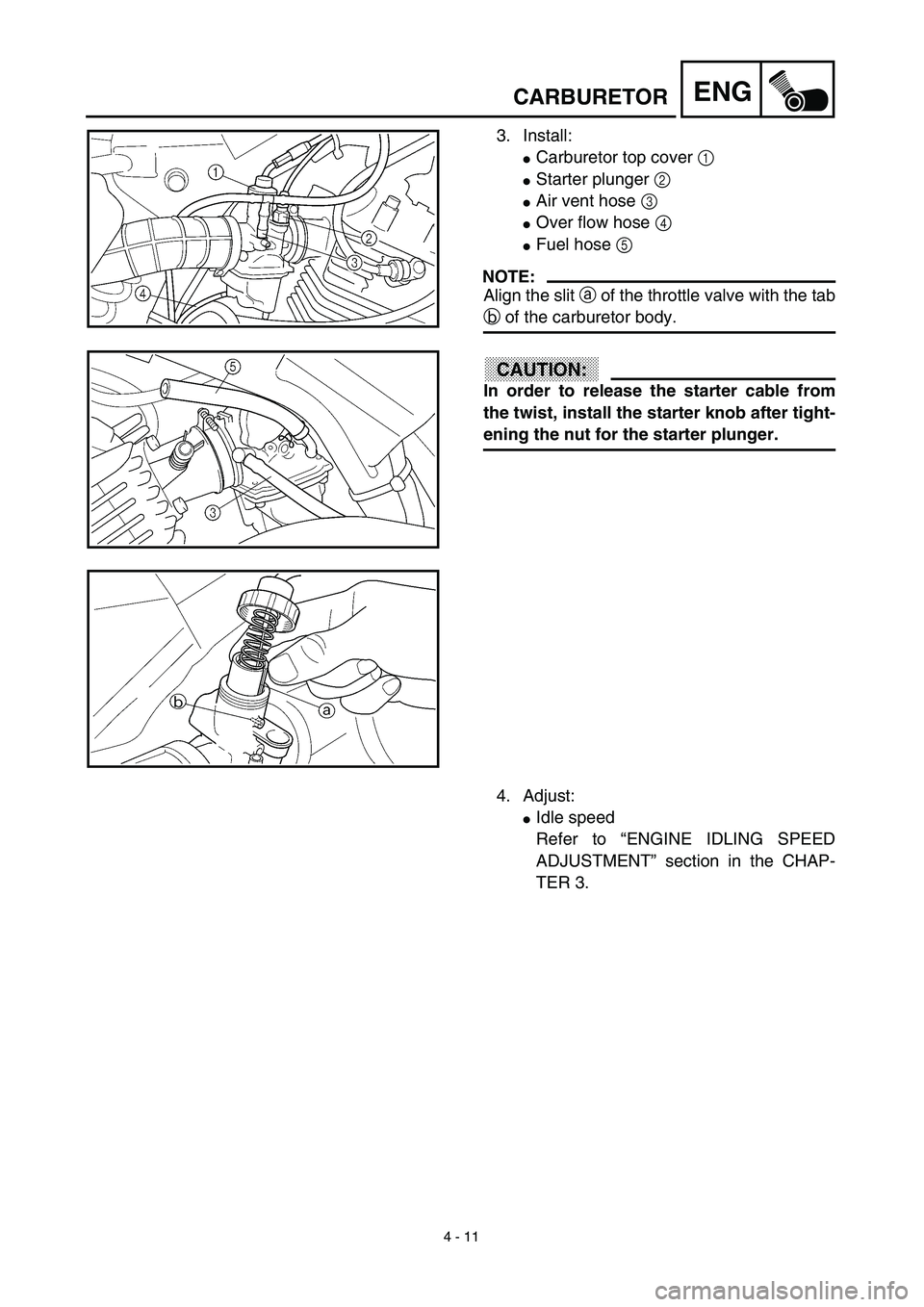
3. Install:
�Carburetor top cover 1
�Starter plunger 2
�Air vent hose 3
�Over flow hose 4
�Fuel hose 5
NOTE:
Align the slit a of the throttle valve with the tab
b of the carburetor body.
CAUTION:
In order to release the starter cable from
the twist, install the starter knob after tight-
ening the nut for the starter plunger.
4. Adjust:
�Idle speed
Refer to “ENGINE IDLING SPEED
ADJUSTMENT” section in the CHAP-
TER 3.
Page 268 of 578
4 - 12
ENGCYLINDER HEAD
CYLINDER HEAD
CYLINDER HEAD SIDE COVER AND TAPPET COVER
Extent of removal:1 Cylinder head side cover and tappet cover removal
Extent of removal Order Part name Q’ty Remarks
CYLINDER HEAD SIDE COVER
AND TAPPET COVER
REMOVAL
Preparation for removal Seat and fuel tank Refer to “SEAT, FUEL TANK AND SIDE
COVERS” section.
Muffler Refer to “MUFFLER” section.
Carburetor Refer to “CARBURETOR” section.
CDI unit Remove from the frame.
1 Engine bracket 1
2 Spark plug 1
3 Cylinder head side cover 1
4 Tappet cover 2
5 Crankshaft end accessing screw 1
6Timing mark accessing screw
1
1
Page 276 of 578
4 - 16
ENGCYLINDER HEAD
Warpage limit:
0.03 mm (0.0012 in)
�If the warpage is out of specification,
resurface the cylinder head.
�Place #400 ~ 600 grit wet sandpaper on
the surface plate, and re-surface the head
using a figure-eight sanding pattern.
NOTE:
Rotate the cylinder head several times to
avoid removing too much material from one
side.
ASSEMBLY AND INSTALLATION
Cylinder head
1. Install:
�Dowel pin 1
�Gasket 2 New
2. Install:
�Cylinder head
�Copper washer
�Bolt (cylinder head)
NOTE:
�Apply Quick gasket® (YAMAHA Bond
No.1215) on end of the cylinder head bolts
(M6), as shown.
�Apply the engine oil on the contact surfaces of
the bolts (cylinder head) and copper washers.
�Follow the numerical order shown in the illus-
tration. Tighten the bolts in two stages.
Quick gasket®:
ACC-QUICK-GS-KT
YAMAHA Bond No.1215:
90890-85505
T R..M8 22 Nm (2.2 m · kg, 16 ft · lb)
M6 10 Nm (1.0 m · kg, 7.2 ft · lb)
Page 282 of 578
4 - 19
ENGCYLINDER HEAD
9. Check:
�Valve clearance
Out of specification → Adjust.
Refer to “VALVE CLEARANCE
INSPECTION AND ADJUSTMENT”
section in the CHAPTER 3.
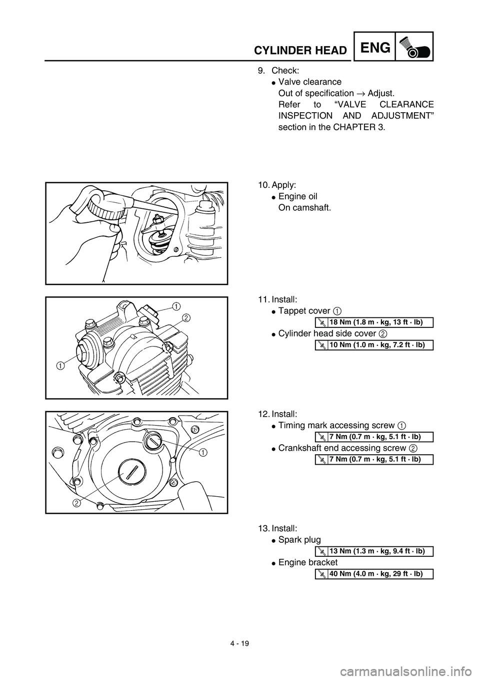
10. Apply:
�Engine oil
On camshaft.
11. Install:
�Tappet cover 1
�Cylinder head side cover 2
T R..18 Nm (1.8 m · kg, 13 ft · lb)
T R..10 Nm (1.0 m · kg, 7.2 ft · lb)
12. Install:
�Timing mark accessing screw 1
�Crankshaft end accessing screw 2
T R..7 Nm (0.7 m · kg, 5.1 ft · lb)
T R..7 Nm (0.7 m · kg, 5.1 ft · lb)
13. Install:
�Spark plug
�Engine bracket
T R..13 Nm (1.3 m · kg, 9.4 ft · lb)
T R..40 Nm (4.0 m · kg, 29 ft · lb)
Page 288 of 578
4 - 22
ENGCAMSHAFT AND ROCKER ARMS
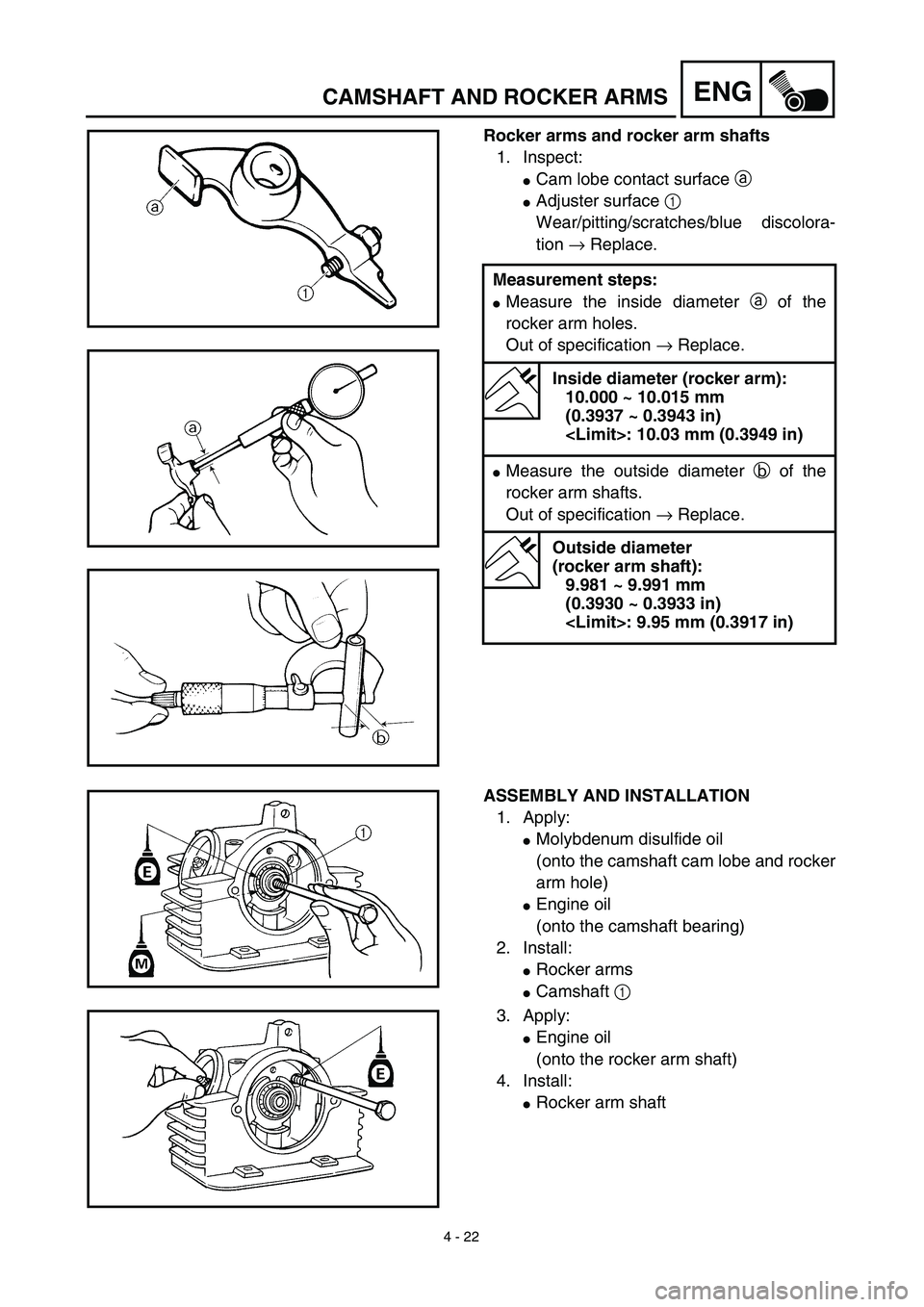
Rocker arms and rocker arm shafts
1. Inspect:
�Cam lobe contact surface a
�Adjuster surface 1
Wear/pitting/scratches/blue discolora-
tion → Replace.
Measurement steps:
�Measure the inside diameter a of the
rocker arm holes.
Out of specification → Replace.
Inside diameter (rocker arm):
10.000 ~ 10.015 mm
(0.3937 ~ 0.3943 in)
: 10.03 mm (0.3949 in)
�Measure the outside diameter b of the
rocker arm shafts.
Out of specification → Replace.
Outside diameter
(rocker arm shaft):
9.981 ~ 9.991 mm
(0.3930 ~ 0.3933 in)
: 9.95 mm (0.3917 in)
ASSEMBLY AND INSTALLATION
1. Apply:
�Molybdenum disulfide oil
(onto the camshaft cam lobe and rocker
arm hole)
�Engine oil
(onto the camshaft bearing)
2. Install:
�Rocker arms
�Camshaft 1
3. Apply:
�Engine oil
(onto the rocker arm shaft)
4. Install:
�Rocker arm shaft
Page 320 of 578

NOTE:
�Be sure to install the 2nd piston ring so that
the manufacturer’s ma")
4 - 38
ENGCYLINDER AND PISTON
ASSEMBLY AND INSTALLATION
Piston ring and piston
1. Install:
�Piston rings
(onto the piston)
NOTE:
�Be sure to install the 2nd piston ring so that
the manufacturer’s mark or number are
located on the upper side of the ring.
�Lubricate the piston and piston rings liberally
with engine oil.
2. Position:
�Top ring
�2nd ring
�Oil ring
Offset the piston ring end gaps as
shown.
a: Top ring end
b: 2nd ring end
c: Oil ring end (upper)
d: Oil ring end (lower)
3. Install:
�Piston 1
�Piston pin 2
�Piston pin clips 3
NOTE:
�Apply engine oil onto the piston pin, piston
rings and piston.
�Be sure that the arrow mark a on the piston
points to the exhaust side of the engine.
�Before installing the piston pin clip, cover the
crankcase with a clean rag to prevent the
piston pin clip from falling into the crankcase.
�When removing the piston pin clip, pop it out
using the small opening b.
4. Lubricate:
�Piston
�Piston rings
�Inside of cylinder
NOTE:
Apply a liberal coating of engine oil.
New
Page 324 of 578
4 - 40
ENGCLUTCH AND PRIMARY DRIVEN GEAR
EC490000
CLUTCH AND PRIMARY DRIVEN GEAR
EC498000
CLUTCH PLATE AND FRICTION PLATE
Extent of removal:1 Clutch plate and friction plate removal
Extent of removal Order Part name Q’ty Remarks
CLUCTH PLATE AND FRIC-
TION PLATE REMOVAL
Preparation for removal Drain the engine oil. Refer to “ENGINE OIL REPLACEMENT”
section in the CHAPTER 3.
Engine skidplate Refer to “ENGINE REMOVAL” section.
Starter motor 1 Refer to “ELECTRIC STARTING SYS-
TEM” section in the CHAPTER 6.
1 Kickstarter crank 1
2 Right crankcase cover 1
3 Gasket 1
4 Dowel pin 2
5 Clutch spring 4
6 Pressure plate 1
7 Ball 1
8 Friction plate 5
9 Clutch plate 4
10 Nut/washer 1/1
11 Push rod 1 1
12 Push plate 1
1