Page 366 of 578

4 - 61
ENG
3. Install the starter clutch
1
on the rotor
2
.
NOTE:
�
Install the starter clutch with its plate portion
a
facing the rotor.
�
Insert the plate portion of the starter clutch
so that it is flush with the surface of contact
b
with the rotor.
12 b
a
4. Tighten:
�
Bolt (starter clutch)
NOTE:
Caulk
a
the end of the starter clutch holding
bolt near its outer diameter to serve as a stop-
per.
a
T R..30 Nm (3.0 m · kg, 22 ft · lb)
5. Install:
�
Starter wheel gear
1
�
Woodruff key
2
�
Rotor
3
NOTE:
�
Clean the tapered portion of the crankshaft
and the magneto hub.
�
When installing the magneto rotor, make
sure the woodruff key is properly seated in
the key way of the crankshaft.
�
Apply the engine oil on the starter wheel
gear inner circumference.
6. Tighten:
�
Nut (magneto)
1
NOTE:
Tighten the nut (magneto)
1
while holding the
magneto
2
with a sheave holder
3
.
Sheave holder:
YS-1880-A/90890-01701
2
1
3
E
T R..80 Nm (8.0 m · kg, 58 ft · lb)
CDI MAGNETO AND STARTER CLUTCH
Page 370 of 578
4 - 63
ENG
ENGINE REMOVAL
ENGINE REMOVAL
Extent of removal:
1
Engine removal
Extent of removal Order Part name Q’ty Remarks
ENGINE REMOVAL
Preparation for removal Hold the machine by placing the
suitable stand under the frame.
Seat, fuel tank and side covers Refer to “SEAT, FUEL TANK AND SIDE
COVERS” section.
Carburetor Refer to “CARBURETOR” section.
Muffler Refer to “MUFFLER” section.
Clutch cable Disconnect at engine side.
Spark plug cap
Disconnect the CDI magneto
lead.
Disconnect the neutral switch
lead.
Starter motor Refer to “ELECTRIC STARTING SYS-
TEM” section in the CHAPTER 6.
Drain the engine oil. Refer to “ENGINE OIL REPLACEMENT”
section in the CHAPTER 3.
Page 372 of 578
4 - 64
ENG
ENGINE REMOVAL
Extent of removal Order Part name Q’ty Remarks
1 Drive sprocket cover 1
2 Bolt (drive sprocket) 2
Refer to “REMOVAL POINTS”. 3 Drive sprocket holder 1
4 Drive sprocket 1
5 Shift pedal link 1
6 Crankcase breather hose 1
7 Engine bracket (upper) 1
8 Engine skidplate 1
9 Engine bracket (front) 1
10 Engine mounting bolt (rear) 2
11Engine
1Refer to “REMOVAL POINTS”.
1
Page 374 of 578
4 - 65
ENG
ENGINE REMOVAL
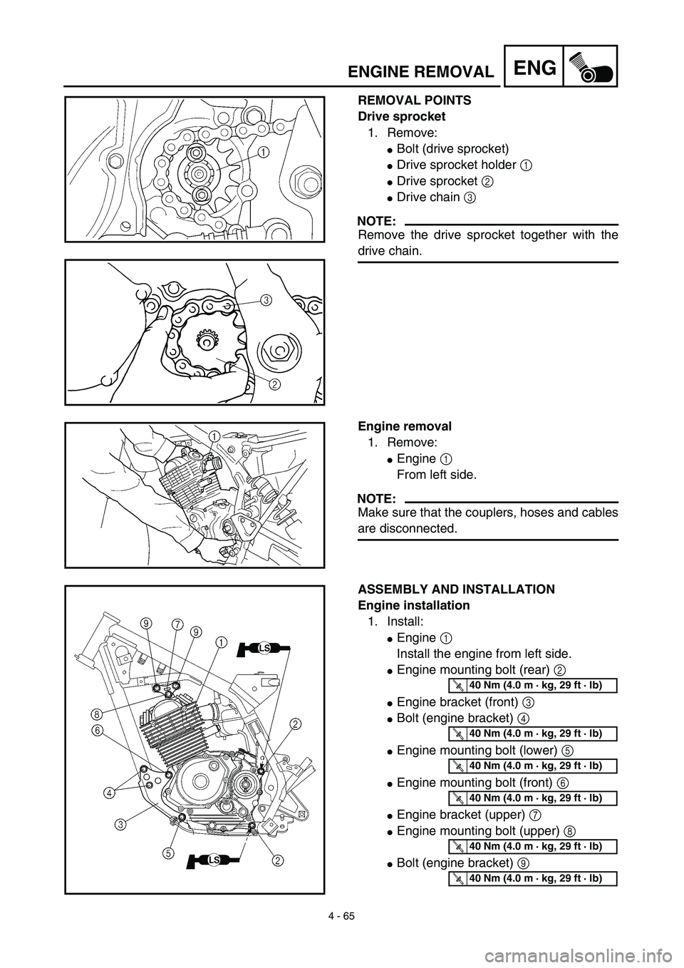
REMOVAL POINTS
Drive sprocket
1. Remove:
�
Bolt (drive sprocket)
�
Drive sprocket holder
1
�
Drive sprocket
2
�
Drive chain
3
NOTE:
Remove the drive sprocket together with the
drive chain.
Engine removal
1. Remove:
�
Engine
1
From left side.
NOTE:
Make sure that the couplers, hoses and cables
are disconnected.
ASSEMBLY AND INSTALLATION
Engine installation
1. Install:
�
Engine
1
Install the engine from left side.
�
Engine mounting bolt (rear)
2
�
Engine bracket (front)
3
�
Bolt (engine bracket)
4
�Engine mounting bolt (lower) 5
�Engine mounting bolt (front) 6
�Engine bracket (upper) 7
�Engine mounting bolt (upper) 8
�Bolt (engine bracket) 9
T R..40 Nm (4.0 m · kg, 29 ft · lb)
T R..40 Nm (4.0 m · kg, 29 ft · lb)
T R..40 Nm (4.0 m · kg, 29 ft · lb)
T R..40 Nm (4.0 m · kg, 29 ft · lb)
T R..40 Nm (4.0 m · kg, 29 ft · lb)
T R..40 Nm (4.0 m · kg, 29 ft · lb)
Page 376 of 578
4 - 66
ENGENGINE REMOVAL
NOTE:
�Apply the lithium soap base grease on the
thread of the engine mounting bolts (rear) 2.
�Tighten the engine mounting bolt (upper) 8,
and then tighten the bolts (engine bracket)
9.
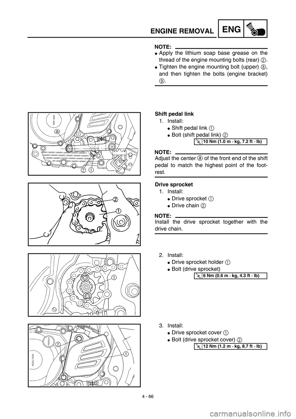
Shift pedal link
1. Install:
�Shift pedal link 1
�Bolt (shift pedal link) 2
NOTE:
Adjust the center a of the front end of the shift
pedal to match the highest point of the foot-
rest.
T R..10 Nm (1.0 m · kg, 7.2 ft · lb)
Drive sprocket
1. Install:
�Drive sprocket 1
�Drive chain 2
NOTE:
Install the drive sprocket together with the
drive chain.
2. Install:
�Drive sprocket holder 1
�Bolt (drive sprocket)
T R..6 Nm (0.6 m · kg, 4.3 ft · lb)
3. Install:
�Drive sprocket cover 1
�Bolt (drive sprocket cover) 2
T R..12 Nm (1.2 m · kg, 8.7 ft · lb)
Page 378 of 578
4 - 67
ENGCRANKCASE, CRANKSHAFT AND BALANCER
CRANKCASE, CRANKSHAFT AND BALANCER
Extent of removal:1 Crankcase separation2 Balancer removal
3 Crankshaft removal
Extent of removal Order Part name Q’ty Remarks
CRANKCASE, CRANKSHAFT
AND BALANCER REMOVAL
Preparation for removal Engine Refer to “ENGINE REMOVAL” section.
Piston Refer to “CYLINDER AND PISTON” sec-
tion.
Primary drive gear Refer to “CLUTCH AND PRIMARY
DRIVEN GEAR” section.
Kick axle assembly
Refer to “KICK AXLE AND SHIFT
SHAFT” section.
Segment
Rotor and stator Refer to “CDI MAGNETO AND
STARTER CLUTCH” section.
Page 382 of 578

�Lead guide 1
�Clutch cable holder 2
NOTE:
Loosen each bolt 1/4 of a turn at a time and
after all t")
4 - 69
ENGCRANKCASE, CRANKSHAFT AND BALANCER
REMOVAL POINTS
Crankcase
1. Remove:
�Bolt (crankcase)
�Lead guide 1
�Clutch cable holder 2
NOTE:
Loosen each bolt 1/4 of a turn at a time and
after all the bolts are loosened, remove them.
2. Remove:
�Right crankcase 1
Use the crankcase separating tool 2.
NOTE:
�Fully tighten the tool holding bolts, but make
sure the tool body is parallel with the case. If
necessary, one screw may be backed out
slightly to level tool body.
�As pressure is applied, alternately tap on the
front engine mounting boss and transmission
shafts.
CAUTION:
Use soft hammer to tap on the case half.
Tap only on reinforced portions of case. Do
not tap on gasket mating surface. Work
slowly and carefully. Make sure the case
halves separate evenly. If one end “hangs
up”, take pressure off the push screw, re-
align, and start over. If the cases do not
separate, check for a remaining case screw
or fitting. Do not force.
Crankcase separating tool:
YU-1135-A/90890-01135
Page 386 of 578
4 - 71
ENGCRANKCASE, CRANKSHAFT AND BALANCER
Crankcase
1. Inspect:
�Contacting surface a
Scratches → Replace.
�Engine mounting boss b, crankcase
Cracks/damage → Replace.
2. Inspect:
�Bearing
Rotate inner race with a finger.
Rough spot/seizure → Replace.
Crankshaft
1. Measure:
�Runout limit a
�Connecting rod big end side clearance
b
�Crank width c
Out of specification → Replace.
Use the dial gauge and a thickness
gauge.
Dial gauge & stand set:
YU-3097/90890-01252
Standard
Runout
limit:—0.03 mm
(0.0012 in)
Side
clearance:0.15 ~ 0.45 mm
(0.0059 ~ 0.0177 in)0.50 mm
(0.02 in)
Crack
width:46.95 ~ 47.00 mm
(1.848 ~ 1.850 in)—

 2
Refer to “REMOVAL POINTS”. 3 Drive sprocket holder 1
4 Drive spro")