Page 28 of 578
1 - 1
GEN
INFO
DESCRIPTION
EC100000
GENERAL INFORMATION
EC110000
DESCRIPTION
1
Clutch lever
2
Engine stop switch
3
Main switch
4
Starter knob
5
Start switch
6
Front brake lever
7
Throttle grip
8
Fuel tank cap
9
Air filter
0
Kickstarter crank
A
Fuel tank
B
Dipstick
C
Rear brake pedal
D
Fuel cock
E
Drive chain
F
Shift pedal
G
Front fork
*The illustration shows the TT-R125LWE.
NOTE:
�
The machine you have purchased may differ
slightly from those shown in the following.
�
Designs and specifications are subject to
change without notice.
90A
CB
D
FE G
12 34 5 6
7 8
Page 52 of 578

1 - 11
GEN
INFO
CONTROL FUNCTIONS
EC158010
FUEL COCK
The fuel cock supplies fuel from the tank to
carburetor while filtering the fuel. The fuel cock
has the three positions:
OFF: With the lever in this position, fuel will
not flow. Always return the lever to this
position when the engine is not running.
ON: With the lever in this position, fuel flows
to the carburetor. Normal riding is done
with the lever in this position.
RES: This indicates reserve. If you run out of
fuel while riding, move the lever to this
position. FILL THE TANK AT THE
FIRST OPPORTUNITY. BE SURE TO
SET THE LEVER TO “ON” AFTER
REFUELING.
EC159000
STARTER KNOB (CHOKE)
When cold, the engine requires a richer air-fuel
mixture for starting. A separate starter circuit,
which is controlled by the starter knob 1, sup-
plies this mixture. Pull the starter knob out to
open the circuit for starting. When the engine
has warmed up, push it in to close the circuit.
FUEL TANK CAP
Remove the fuel tank cap 1 by turning coun-
terclockwise.
WARNING
Do not overfill the fuel tank. Avoid spilling
fuel on the hot engine.
1
SIDESTAND
This sidestand 1 is used to support only the
machine when standing or transporting it.
WARNING
�Never apply additional force to the side-
stand.
�Hold up the sidestand before starting out.
Page 54 of 578
1 - 12
GEN
INFO
FUEL
Use regular gasoline. Always use fresh, name
brand gasoline.
WARNING
Do not overfill the fuel tank. Avoid spilling
fuel on the hot engine. Do not fill the fuel
tank above the bottom of the filler tube 1
as shown in the illustration or it may over-
flow when the fuel heats up later and
expands.
aFuel level
CAUTION:
Use only unleaded gasoline. The use of
leaded gasoline will cause severe damage
to the engine internal parts such as valves,
piston rings, and exhaust system, etc.
Recommended fuel:
For USA, AUS and NZ:
Unleaded gasoline only
For CDN and EUROPE:
Regular unleaded gasoline
only
For ZA:
Regular gasoline
Fuel tank capacity:
Total:
6.6 L (1.45 lmp gal, 1.74 US gal)
Reserve:
1.9 L (0.42 Imp gal, 0.5 US gal)
FUEL
Page 73 of 578

SPEC
2 - 2
GENERAL SPECIFICATIONS
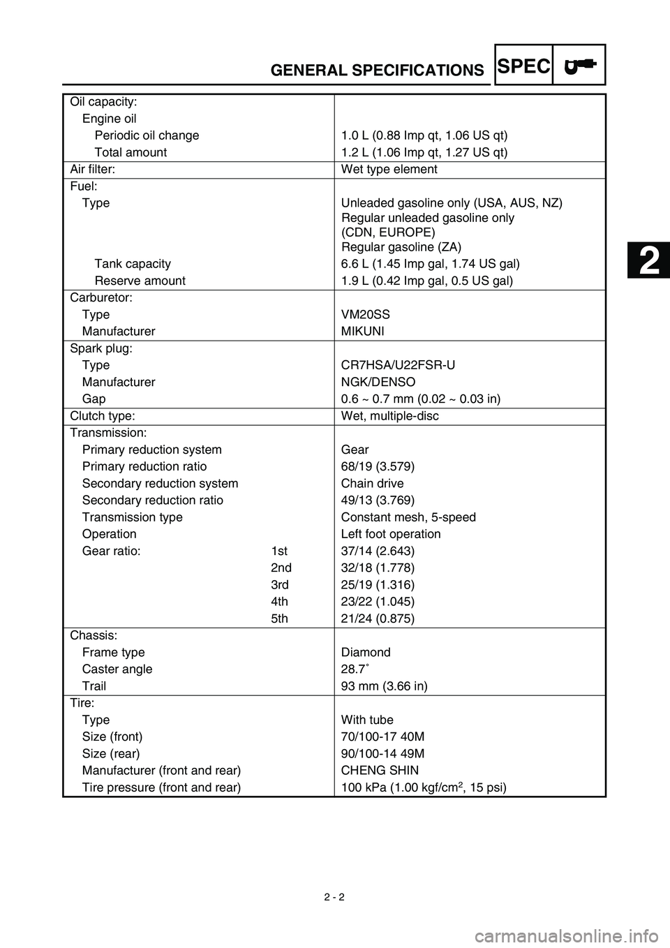
Oil capacity:
Engine oil
Periodic oil change 1.0 L (0.88 Imp qt, 1.06 US qt)
Total amount 1.2 L (1.06 Imp qt, 1.27 US qt)
Air filter: Wet type element
Fuel:
Type Unleaded gasoline only (USA, AUS, NZ)
Regular unleaded gasoline only
(CDN, EUROPE)
Regular gasoline (ZA)
Tank capacity 6.6 L (1.45 Imp gal, 1.74 US gal)
Reserve amount 1.9 L (0.42 Imp gal, 0.5 US gal)
Carburetor:
Type VM20SS
Manufacturer MIKUNI
Spark plug:
Type CR7HSA/U22FSR-U
Manufacturer NGK/DENSO
Gap 0.6 ~ 0.7 mm (0.02 ~ 0.03 in)
Clutch type: Wet, multiple-disc
Transmission:
Primary reduction system Gear
Primary reduction ratio 68/19 (3.579)
Secondary reduction system Chain drive
Secondary reduction ratio 49/13 (3.769)
Transmission type Constant mesh, 5-speed
Operation Left foot operation
Gear ratio: 1st 37/14 (2.643)
2nd 32/18 (1.778)
3rd 25/19 (1.316)
4th 23/22 (1.045)
5th 21/24 (0.875)
Chassis:
Frame type Diamond
Caster angle 28.7˚
Trail 93 mm (3.66 in)
Tire:
Type With tube
Size (front) 70/100-17 40M
Size (rear) 90/100-14 49M
Manufacturer (front and rear) CHENG SHIN
Tire pressure (front and rear) 100 kPa (1.00 kgf/cm
2
, 15 psi)
2
Page 76 of 578

SPEC
2 - 5
GENERAL SPECIFICATIONS
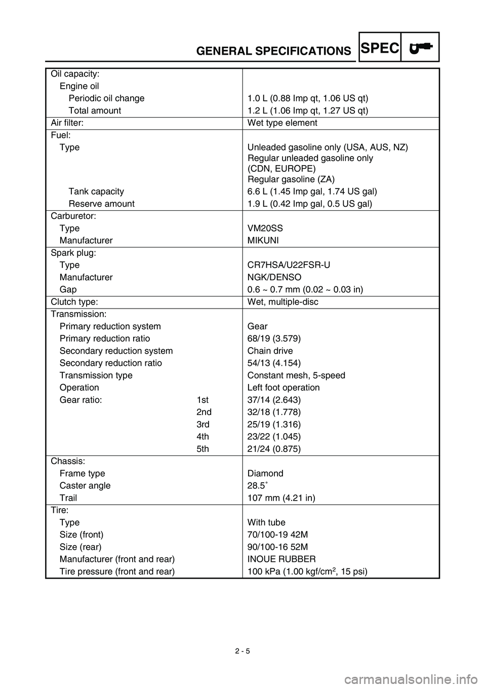
Oil capacity:
Engine oil
Periodic oil change 1.0 L (0.88 Imp qt, 1.06 US qt)
Total amount 1.2 L (1.06 Imp qt, 1.27 US qt)
Air filter: Wet type element
Fuel:
Type Unleaded gasoline only (USA, AUS, NZ)
Regular unleaded gasoline only
(CDN, EUROPE)
Regular gasoline (ZA)
Tank capacity 6.6 L (1.45 Imp gal, 1.74 US gal)
Reserve amount 1.9 L (0.42 Imp gal, 0.5 US gal)
Carburetor:
Type VM20SS
Manufacturer MIKUNI
Spark plug:
Type CR7HSA/U22FSR-U
Manufacturer NGK/DENSO
Gap 0.6 ~ 0.7 mm (0.02 ~ 0.03 in)
Clutch type: Wet, multiple-disc
Transmission:
Primary reduction system Gear
Primary reduction ratio 68/19 (3.579)
Secondary reduction system Chain drive
Secondary reduction ratio 54/13 (4.154)
Transmission type Constant mesh, 5-speed
Operation Left foot operation
Gear ratio: 1st 37/14 (2.643)
2nd 32/18 (1.778)
3rd 25/19 (1.316)
4th 23/22 (1.045)
5th 21/24 (0.875)
Chassis:
Frame type Diamond
Caster angle 28.5˚
Trail 107 mm (4.21 in)
Tire:
Type With tube
Size (front) 70/100-19 42M
Size (rear) 90/100-16 52M
Manufacturer (front and rear) INOUE RUBBER
Tire pressure (front and rear) 100 kPa (1.00 kgf/cm
2
, 15 psi)
Page 220 of 578

3 - 29
INSP
ADJ
STEERING HEAD INSPECTION AND ADJUSTMENT
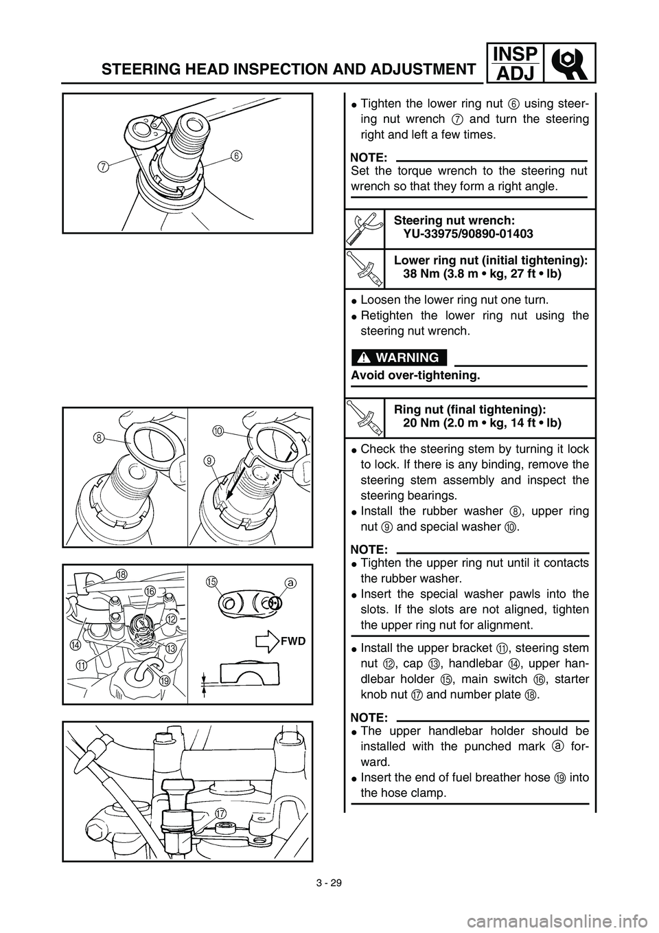
�Tighten the lower ring nut 6 using steer-
ing nut wrench 7 and turn the steering
right and left a few times.
Steering nut wrench:
YU-33975/90890-01403
T R..
Lower ring nut (initial tightening):
38 Nm (3.8 m • kg, 27 ft • lb)
�Loosen the lower ring nut one turn.
�Retighten the lower ring nut using the
steering nut wrench.
T R..
Ring nut (final tightening):
20 Nm (2.0 m • kg, 14 ft • lb)
�Check the steering stem by turning it lock
to lock. If there is any binding, remove the
steering stem assembly and inspect the
steering bearings.
�Install the rubber washer 8, upper ring
nut 9 and special washer 0.
NOTE:
�Tighten the upper ring nut until it contacts
the rubber washer.
�Insert the special washer pawls into the
slots. If the slots are not aligned, tighten
the upper ring nut for alignment.
�Install the upper bracket A, steering stem
nut B, cap C, handlebar D, upper han-
dlebar holder E, main switch F, starter
knob nut G and number plate H.
NOTE:
�The upper handlebar holder should be
installed with the punched mark a for-
ward.
�Insert the end of fuel breather hose I into
the hose clamp.
NOTE:
Set the torque wrench to the steering nut
wrench so that they form a right angle.
WARNING
Avoid over-tightening.
H
DF
B
C
I
A
Page 370 of 578
4 - 63
ENG
ENGINE REMOVAL
ENGINE REMOVAL
Extent of removal:
1
Engine removal
Extent of removal Order Part name Q’ty Remarks
ENGINE REMOVAL
Preparation for removal Hold the machine by placing the
suitable stand under the frame.
Seat, fuel tank and side covers Refer to “SEAT, FUEL TANK AND SIDE
COVERS” section.
Carburetor Refer to “CARBURETOR” section.
Muffler Refer to “MUFFLER” section.
Clutch cable Disconnect at engine side.
Spark plug cap
Disconnect the CDI magneto
lead.
Disconnect the neutral switch
lead.
Starter motor Refer to “ELECTRIC STARTING SYS-
TEM” section in the CHAPTER 6.
Drain the engine oil. Refer to “ENGINE OIL REPLACEMENT”
section in the CHAPTER 3.