Page 26 of 578

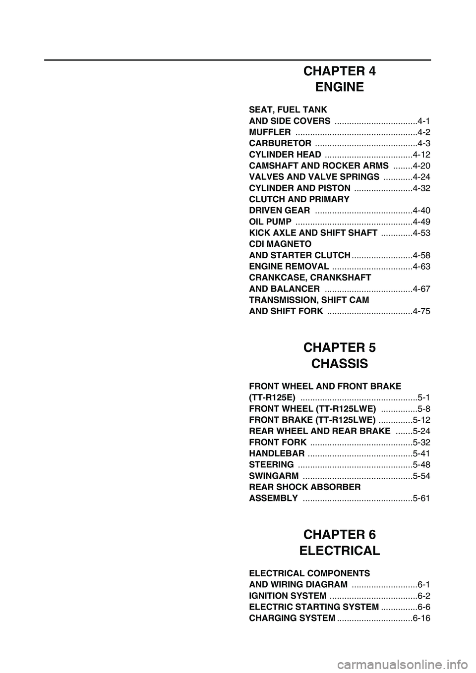
CHAPTER 4
ENGINE
SEAT, FUEL TANK
AND SIDE COVERS
..................................4-1
MUFFLER
..................................................4-2
CARBURETOR
..........................................4-3
CYLINDER HEAD
....................................4-12
CAMSHAFT AND ROCKER ARMS
........4-20
VALVES AND VALVE SPRINGS
............4-24
CYLINDER AND PISTON
........................4-32
CLUTCH AND PRIMARY
DRIVEN GEAR
........................................4-40
OIL PUMP
................................................4-49
KICK AXLE AND SHIFT SHAFT
.............4-53
CDI MAGNETO
AND STARTER CLUTCH
.........................4-58
ENGINE REMOVAL
.................................4-63
CRANKCASE, CRANKSHAFT
AND BALANCER
....................................4-67
TRANSMISSION, SHIFT CAM
AND SHIFT FORK
...................................4-75
CHAPTER 5
CHASSIS
FRONT WHEEL AND FRONT BRAKE
(TT-R125E)
................................................5-1
FRONT WHEEL (TT-R125LWE)
...............5-8
FRONT BRAKE (TT-R125LWE)
..............5-12
REAR WHEEL AND REAR BRAKE
.......5-24
FRONT FORK
..........................................5-32
HANDLEBAR
...........................................5-41
STEERING
...............................................5-48
SWINGARM
.............................................5-54
REAR SHOCK ABSORBER
ASSEMBLY
.............................................5-61
CHAPTER 6
ELECTRICAL
ELECTRICAL COMPONENTS
AND WIRING DIAGRAM
...........................6-1
IGNITION SYSTEM
....................................6-2
ELECTRIC STARTING SYSTEM
...............6-6
CHARGING SYSTEM
...............................6-16
Page 28 of 578
1 - 1
GEN
INFO
DESCRIPTION
EC100000
GENERAL INFORMATION
EC110000
DESCRIPTION
1
Clutch lever
2
Engine stop switch
3
Main switch
4
Starter knob
5
Start switch
6
Front brake lever
7
Throttle grip
8
Fuel tank cap
9
Air filter
0
Kickstarter crank
A
Fuel tank
B
Dipstick
C
Rear brake pedal
D
Fuel cock
E
Drive chain
F
Shift pedal
G
Front fork
*The illustration shows the TT-R125LWE.
NOTE:
�
The machine you have purchased may differ
slightly from those shown in the following.
�
Designs and specifications are subject to
change without notice.
90A
CB
D
FE G
12 34 5 6
7 8
Page 39 of 578

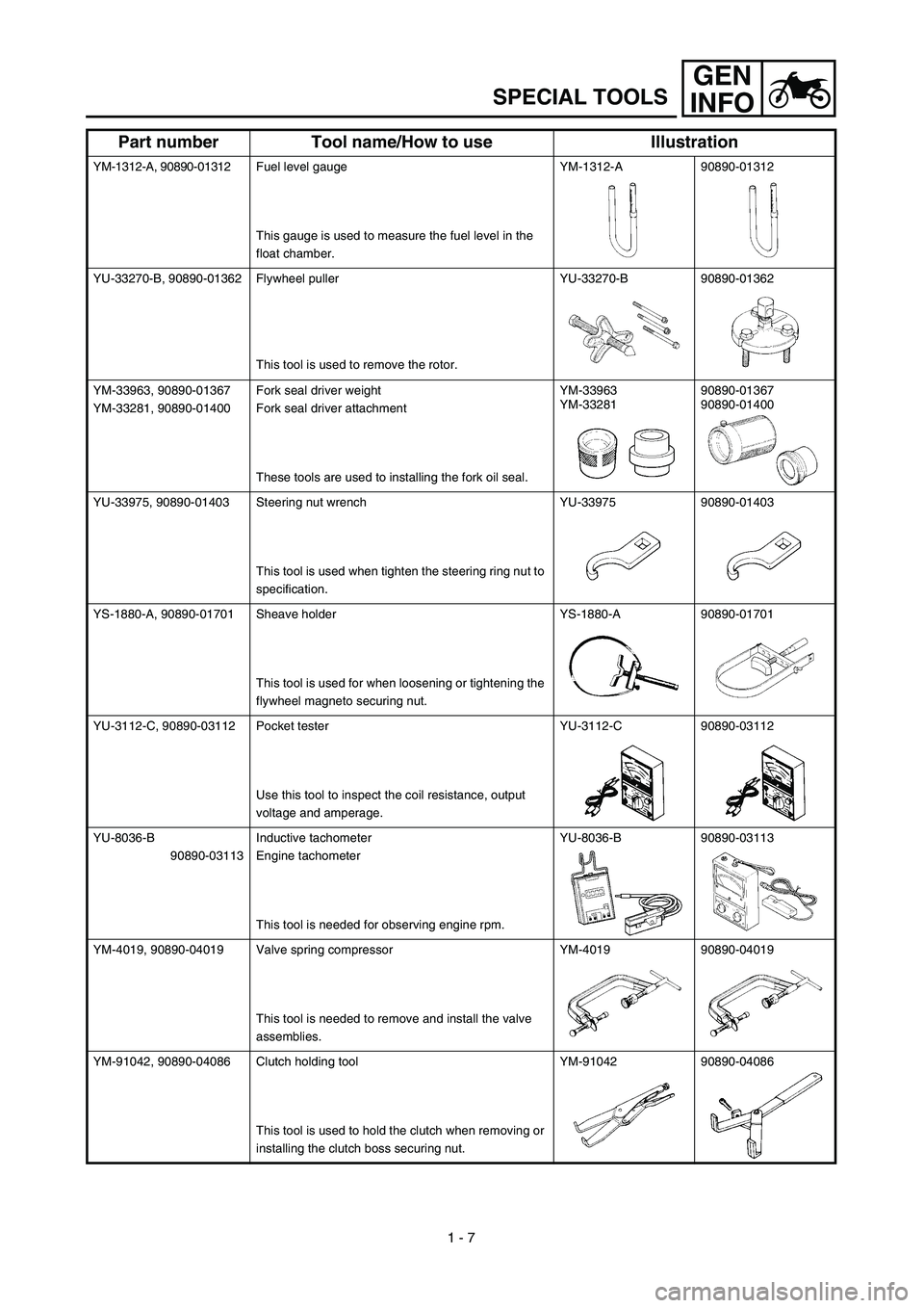
1 - 7
GEN
INFO
SPECIAL TOOLS
YM-1312-A, 90890-01312Fuel level gauge
This gauge is used to measure the fuel level in the
float chamber.YM-1312-A 90890-01312
YU-33270-B, 90890-01362 Flywheel puller
This tool is used to remove the rotor.YU-33270-B 90890-01362
YM-33963, 90890-01367
YM-33281, 90890-01400Fork seal driver weight
Fork seal driver attachment
These tools are used to installing the fork oil seal.YM-33963
YM-3328190890-01367
90890-01400
YU-33975, 90890-01403 Steering nut wrench
This tool is used when tighten the steering ring nut to
specification.YU-33975 90890-01403
YS-1880-A, 90890-01701 Sheave holder
This tool is used for when loosening or tightening the
flywheel magneto securing nut.YS-1880-A 90890-01701
YU-3112-C, 90890-03112 Pocket tester
Use this tool to inspect the coil resistance, output
voltage and amperage.YU-3112-C 90890-03112
YU-8036-B
90890-03113Inductive tachometer
Engine tachometer
This tool is needed for observing engine rpm.YU-8036-B 90890-03113
YM-4019, 90890-04019 Valve spring compressor
This tool is needed to remove and install the valve
assemblies.YM-4019 90890-04019
YM-91042, 90890-04086 Clutch holding tool
This tool is used to hold the clutch when removing or
installing the clutch boss securing nut.YM-91042 90890-04086
Part number Tool name/How to use Illustration
Page 48 of 578

1 - 9
GEN
INFO
CONTROL FUNCTIONS
EC150000
CONTROL FUNCTIONS
MAIN SWITCH
Functions of the respective switch positions
are as follows:
ON: The engine can be started only at this
position.
OFF: All electrical circuits are switched off.
The key can be removed in this position.
ENGINE STOP SWITCH
The engine stop switch 1 is located on the left
handlebar. Continue pushing the engine stop
switch till the engine comes to a stop.
START SWITCH
The start switch 1 is located on the right han-
dlebar. Push this switch to crank the engine
with the starter.
1
EC152000
CLUTCH LEVER
The clutch lever 1 is located on the left han-
dlebar; it disengages or engages the clutch.
Pull the clutch lever to the handlebar to disen-
gage the clutch, and release the lever to
engage the clutch. The lever should be pulled
rapidly and released slowly for smooth starts.
EC153000
SHIFT PEDAL
The gear ratios of the constant-mesh 5 speed
transmission are ideally spaced. The gears
can be shifted by using the shift pedal 1 on
the left side of the engine.
Page 56 of 578

1 - 13
GEN
INFO
STARTING AND BREAK-IN
EC190000
STARTING AND BREAK-IN
CAUTION:
Before starting the machine, perform the
checks in the pre-operation check list.
WARNING
Never start or run the engine in a closed
area. The exhaust fumes are poisonous;
they can cause loss of consciousness and
death in a very short time. Always operate
the machine in a well-ventilated area.
STARTING A COLD ENGINE
NOTE:
This model is equipped with an ignition circuit
cut-off system. The engine can be started
under the following conditions.
�When the transmission is in neutral.
�When the clutch is disengaged with the
transmission in any position. However, it is
recommended to shift into neutral before
starting the engine.
1. Shift the transmission into neutral.
2. Turn the fuel cock to “ON” and full open
the starter knob (CHOKE).
3. Turn the main switch to “ON”.
4. With the throttle completely closed start
the engine by pushing the start switch or
by kicking the kickstarter crank forcefully
with firm stroke.
5. Run the engine at idle or slightly higher
until it warms up: this usually takes about
one or two minutes.
6. The engine is warmed up when it
responds normally to the throttle with the
starter knob (CHOKE) turned off.
Page 60 of 578
1 - 15
GEN
INFO
STARTING AND BREAK-IN
BREAKING IN AFTER REPLACEMENT
After a part is replaced with a new one, it is
necessary to break it in as in a new machine.
This is required especially when the following
engine-related parts are replaced.
�Cylinder
�Piston
�Piston ring
�Valve
�Camshaft
�Crankshaft
�Clutch
�Transmission gear
�Shift fork
* For warming up and inspection during
break-in, refer to “GENERAL INSPECTION
AND MAINTENANCE” section in the
CHAPTER 3 and if there is any problem,
stop the engine immediately and check.
Page 73 of 578

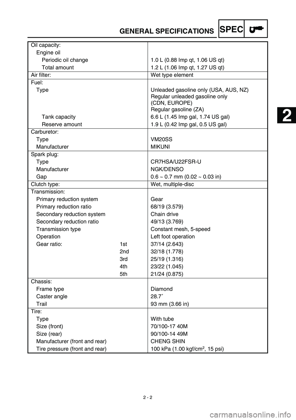
SPEC
2 - 2
GENERAL SPECIFICATIONS
Oil capacity:
Engine oil
Periodic oil change 1.0 L (0.88 Imp qt, 1.06 US qt)
Total amount 1.2 L (1.06 Imp qt, 1.27 US qt)
Air filter: Wet type element
Fuel:
Type Unleaded gasoline only (USA, AUS, NZ)
Regular unleaded gasoline only
(CDN, EUROPE)
Regular gasoline (ZA)
Tank capacity 6.6 L (1.45 Imp gal, 1.74 US gal)
Reserve amount 1.9 L (0.42 Imp gal, 0.5 US gal)
Carburetor:
Type VM20SS
Manufacturer MIKUNI
Spark plug:
Type CR7HSA/U22FSR-U
Manufacturer NGK/DENSO
Gap 0.6 ~ 0.7 mm (0.02 ~ 0.03 in)
Clutch type: Wet, multiple-disc
Transmission:
Primary reduction system Gear
Primary reduction ratio 68/19 (3.579)
Secondary reduction system Chain drive
Secondary reduction ratio 49/13 (3.769)
Transmission type Constant mesh, 5-speed
Operation Left foot operation
Gear ratio: 1st 37/14 (2.643)
2nd 32/18 (1.778)
3rd 25/19 (1.316)
4th 23/22 (1.045)
5th 21/24 (0.875)
Chassis:
Frame type Diamond
Caster angle 28.7˚
Trail 93 mm (3.66 in)
Tire:
Type With tube
Size (front) 70/100-17 40M
Size (rear) 90/100-14 49M
Manufacturer (front and rear) CHENG SHIN
Tire pressure (front and rear) 100 kPa (1.00 kgf/cm
2
, 15 psi)
2
Page 76 of 578

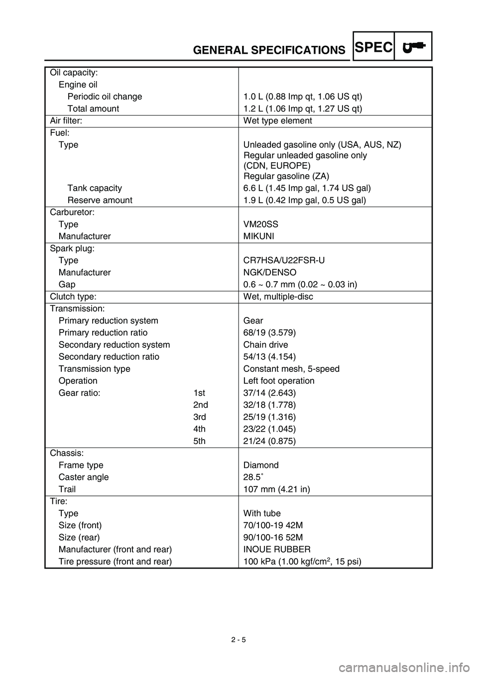
SPEC
2 - 5
GENERAL SPECIFICATIONS
Oil capacity:
Engine oil
Periodic oil change 1.0 L (0.88 Imp qt, 1.06 US qt)
Total amount 1.2 L (1.06 Imp qt, 1.27 US qt)
Air filter: Wet type element
Fuel:
Type Unleaded gasoline only (USA, AUS, NZ)
Regular unleaded gasoline only
(CDN, EUROPE)
Regular gasoline (ZA)
Tank capacity 6.6 L (1.45 Imp gal, 1.74 US gal)
Reserve amount 1.9 L (0.42 Imp gal, 0.5 US gal)
Carburetor:
Type VM20SS
Manufacturer MIKUNI
Spark plug:
Type CR7HSA/U22FSR-U
Manufacturer NGK/DENSO
Gap 0.6 ~ 0.7 mm (0.02 ~ 0.03 in)
Clutch type: Wet, multiple-disc
Transmission:
Primary reduction system Gear
Primary reduction ratio 68/19 (3.579)
Secondary reduction system Chain drive
Secondary reduction ratio 54/13 (4.154)
Transmission type Constant mesh, 5-speed
Operation Left foot operation
Gear ratio: 1st 37/14 (2.643)
2nd 32/18 (1.778)
3rd 25/19 (1.316)
4th 23/22 (1.045)
5th 21/24 (0.875)
Chassis:
Frame type Diamond
Caster angle 28.5˚
Trail 107 mm (4.21 in)
Tire:
Type With tube
Size (front) 70/100-19 42M
Size (rear) 90/100-16 52M
Manufacturer (front and rear) INOUE RUBBER
Tire pressure (front and rear) 100 kPa (1.00 kgf/cm
2
, 15 psi)