Page 340 of 578

4 - 48
ENGCLUTCH AND PRIMARY DRIVEN GEAR
9. Adjust:
�Push lever position
Adjustment steps:
�Loosen the locknut 1.
�Turn the push rod 1 2 clockwise or coun-
terclockwise to match alignment marks.
�Hold the push rod 1 to prevent it from
moving and tighten the locknut to specifi-
cation.
�Tighten the locknut 1.
T R..
Locknut:
8 Nm (0.8 m • kg, 5.8 ft • lb)
10. Install:
�Dowel pins
�Gasket (right crankcase cover)
�Right crankcase cover
�Battery negative lead 1
�Lead holder 2
�Bolts (right crankcase cover)
NOTE:
�Apply Quick gasket® (YAMAHA Bond
No.1215) to end of the right crankcase cover
bolts, as shown.
�Tighten the bolts in stages, using a criss-
cross pattern.
Quick gasket®:
ACC-QUICK-GS-KT
YAMAHA Bond No.1215:
90890-85505
New
T R..10 Nm (1.0 m · kg, 7.2 ft · lb)
11. Install:
�Kickstarter crank 1
�Nut (kickstarter crank) 2
NOTE:
Install the kickstarter crank so that there is 5 ~
10 mm (0.2 ~ 0.4 in) a between the kickstarter
crank and the right crankcase cover.
T R..50 Nm (5.0 m · kg, 36 ft · lb)
Page 342 of 578
4 - 49
ENGOIL PUMP
OIL PUMP
Extent of removal:1 Oil pump removal
Extent of removal Order Part name Q’ty Remarks
OIL PUMP REMOVAL
Preparation for removal Clutch and primary drive gear Refer to “CLUTCH AND PRIMARY
DRIVEN GEAR” section.
1 Rotary filter 1
2 Oil pump drive gear 1
3 Oil pump assembly 1
4 Gasket 1
5Oil strainer
1
1
Page 350 of 578
4 - 53
ENGKICK AXLE AND SHIFT SHAFT
KICK AXLE AND SHIFT SHAFT
KICK AXLE AND SHIFT SHAFT
Extent of removal:1 Kick axle removal2 Shift shaft removal
Extent of removal Order Part name Q’ty Remarks
KICK AXLE AND SHIFT SHAFT
REMOVAL
Preparation for removal Shift pedal link Refer to “ENGINE REMOVAL” section.
Clutch Refer to “CLUTCH AND PRIMARY
DRIVEN GEAR” section.
1 Kick axle assembly 1 Refer to “REMOVAL POINTS”.
2 Circlip 1
3 Washer 1
4 Kick idle gear 1
5 Washer 1
6 Circlip 1
7 Shift shaft 1
8 Circlip 1
9 Torsion spring 1
10 Bolt (stopper lever) 1
11 Stopper lever 1
12 Spring 1
13 Segment 1 Refer to “REMOVAL POINTS”.
1
2
Page 360 of 578
4 - 58
ENGCDI MAGNETO AND STARTER CLUTCH
CDI MAGNETO AND STARTER CLUTCH
Extent of removal:1 Pickup coil/stator removal2 Starter clutch/wheel gear removal
Extent of removal Order Part name Q’ty Remarks
CDI MAGNETO AND STATOR
REMOVAL
Preparation for removal Fuel tank
1 CDI magneto lead 1
2 Neutral switch lead 1
3 Left crankcase cover 1
4 Nut (rotor) 1
Use special tool.
Refer to “REMOVAL POINTS”.
5 Rotor 1
6 Starter clutch 1
7 Woodruff key 1
8 Starter wheel gear 1
9 Plain washer 1
10 Plate (starter idle gear) 1
11 Starter idle gear 1
12 Lead guide 1
13Pickup coil/stator assembly
1
1
2
1
1
Page 362 of 578
4 - 59
ENGCDI MAGNETO AND STARTER CLUTCH
REMOVAL POINTS
Rotor
1. Remove:
�Nut (rotor) 1
�Plain washer 2
Use the sheave holder 3.
Sheave holder:
YS-1880-A/90890-01701
2. Remove:
�Rotor 1
Use the flywheel puller 2.
Flywheel puller:
YU-33270-B/90890-01362
EC4L4000
INSPECTION
EC4L4101
CDI magneto
1. Inspect:
�Rotor inner surface a
�Stator outer surface b
Damage → Inspect the crankshaft
runout and crankshaft bearing.
If necessary, replace CDI magneto and/
or stator.
EC4L4200
Woodruff key
1. Inspect:
�Woodruff key 1
Damage → Replace.
Starter clutch
1. Check:
�Starter clutch
Damage/wear → Replace.
2. Check:
�Idle gear
�Starter clutch gear
Pitting/burrs/chips/roughness/wear →
Replace the defective parts.
Page 364 of 578

4 - 60
ENGCDI MAGNETO AND STARTER CLUTCH
3. Check:
�Starter clutch operation
�Install the starter clutch drive gear 1 onto
the starter clutch 2 and hold the starter
clutch.
�When turning the starter clutch drive gear
counterclockwise ı, the starter clutch and
the starter clutch drive gear should
engage. If the starter clutch drive gear and
starter clutch do not engage, the starter
clutch is faulty and must be replaced.
�When turning the starter clutch drive gear
clockwise Å, it should turn freely.
If the starter clutch drive gear does not
turn freely, the starter clutch is faulty and
must be replaced.
Å
ı
1
2
EC4L5000
ASSEMBLY AND INSTALLATION
CDI magneto
1. Install:
�Stator 1
�Bolt (stator)
�Lead guide
�Screw (lead guide) 2
�Pickup coil 3
�Bolt (pickup coil)
2. Install:
�Stater idle gear 1
�Plate 2
�Bolt 3
�Washer 4
NOTE:
Apply the engine oil on the starter idle gear
inner circumference.
T R..10 Nm (1.0 m · kg, 7.2 ft · lb)LT
T R..7 Nm (0.7 m · kg, 5.1 ft · lb)LT
T R..10 Nm (1.0 m · kg, 7.2 ft · lb)LT
4
1
2
3
ET R..7 Nm (0.7 m · kg, 5.1 ft · lb)
Page 366 of 578

4 - 61
ENG
3. Install the starter clutch
1
on the rotor
2
.
NOTE:
�
Install the starter clutch with its plate portion
a
facing the rotor.
�
Insert the plate portion of the starter clutch
so that it is flush with the surface of contact
b
with the rotor.
12 b
a
4. Tighten:
�
Bolt (starter clutch)
NOTE:
Caulk
a
the end of the starter clutch holding
bolt near its outer diameter to serve as a stop-
per.
a
T R..30 Nm (3.0 m · kg, 22 ft · lb)
5. Install:
�
Starter wheel gear
1
�
Woodruff key
2
�
Rotor
3
NOTE:
�
Clean the tapered portion of the crankshaft
and the magneto hub.
�
When installing the magneto rotor, make
sure the woodruff key is properly seated in
the key way of the crankshaft.
�
Apply the engine oil on the starter wheel
gear inner circumference.
6. Tighten:
�
Nut (magneto)
1
NOTE:
Tighten the nut (magneto)
1
while holding the
magneto
2
with a sheave holder
3
.
Sheave holder:
YS-1880-A/90890-01701
2
1
3
E
T R..80 Nm (8.0 m · kg, 58 ft · lb)
CDI MAGNETO AND STARTER CLUTCH
Page 368 of 578
4 - 62
ENG
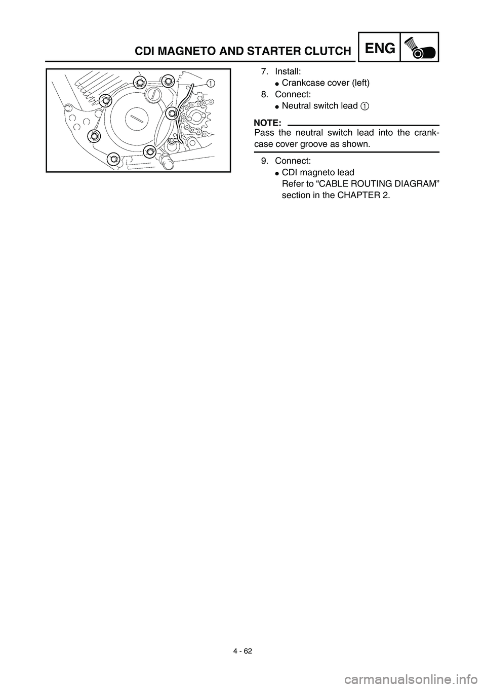
7. Install:
�
Crankcase cover (left)
8. Connect:
�
Neutral switch lead
1
NOTE:
Pass the neutral switch lead into the crank-
case cover groove as shown.
9. Connect:
�
CDI magneto lead
Refer to “CABLE ROUTING DIAGRAM”
section in the CHAPTER 2.
CDI MAGNETO AND STARTER CLUTCH