Page 324 of 578
4 - 40
ENGCLUTCH AND PRIMARY DRIVEN GEAR
EC490000
CLUTCH AND PRIMARY DRIVEN GEAR
EC498000
CLUTCH PLATE AND FRICTION PLATE
Extent of removal:1 Clutch plate and friction plate removal
Extent of removal Order Part name Q’ty Remarks
CLUCTH PLATE AND FRIC-
TION PLATE REMOVAL
Preparation for removal Drain the engine oil. Refer to “ENGINE OIL REPLACEMENT”
section in the CHAPTER 3.
Engine skidplate Refer to “ENGINE REMOVAL” section.
Starter motor 1 Refer to “ELECTRIC STARTING SYS-
TEM” section in the CHAPTER 6.
1 Kickstarter crank 1
2 Right crankcase cover 1
3 Gasket 1
4 Dowel pin 2
5 Clutch spring 4
6 Pressure plate 1
7 Ball 1
8 Friction plate 5
9 Clutch plate 4
10 Nut/washer 1/1
11 Push rod 1 1
12 Push plate 1
1
Page 326 of 578
4 - 41
ENGCLUTCH AND PRIMARY DRIVEN GEAR
EC498100
PRIMARY DRIVEN GEAR
Extent of removal:1 Primary driven gear removal2 Primary drive gear removal
Extent of removal Order Part name Q’ty Remarks
PRIMARY DRIVEN GEAR
REMOVAL
1 Nut (clutch boss) 1
Use special tool.
Refer to “REMOVAL POINTS”. 2 Lock washer 1
3 Clutch boss 1
4 Thrust plate 1
5 Primary driven gear 1
6 Thrust plate 1
7 Conical spring washer 1
8 Nut (primary drive gear) 1
Refer to “REMOVAL POINTS”.
9 Primary drive gear 1
10Straight key
1
2
1
Page 328 of 578
4 - 42
ENGCLUTCH AND PRIMARY DRIVEN GEAR
PUSH LEVER
Extent of removal:1 Push lever removal
Extent of removal Order Part name Q’ty Remarks
PUSH LEVER REMOVAL
1 Clutch cable 1
2 Push lever 1
3 Spring 1
4 Circlip 1
5Oil seal
1
1
Page 330 of 578
4 - 43
ENGCLUTCH AND PRIMARY DRIVEN GEAR
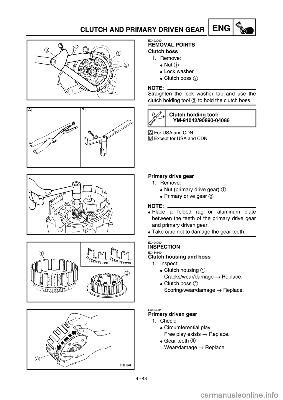
EC493000
REMOVAL POINTS
Clutch boss
1. Remove:
�Nut 1
�Lock washer
�Clutch boss 2
NOTE:
Straighten the lock washer tab and use the
clutch holding tool 3 to hold the clutch boss.
ÅFor USA and CDN
ıExcept for USA and CDN
Clutch holding tool:
YM-91042/90890-04086Å
ı
Primary drive gear
1. Remove:
�Nut (primary drive gear) 1
�Primary drive gear 2
NOTE:
�Place a folded rag or aluminum plate
between the teeth of the primary drive gear
and primary driven gear.
�Take care not to damage the gear teeth.
EC494000
INSPECTION
EC484100
Clutch housing and boss
1. Inspect:
�Clutch housing 1
Cracks/wear/damage → Replace.
�Clutch boss 2
Scoring/wear/damage → Replace.
EC484201
Primary driven gear
1. Check:
�Circumferential play
Free play exists → Replace.
�Gear teeth a
Wear/damage → Replace.
Page 332 of 578
4 - 44
ENGCLUTCH AND PRIMARY DRIVEN GEAR
EC484400
Clutch spring
1. Measure:
�Clutch spring free length a
Out of specification → Replace springs
as a set.
Clutch spring free length:
33 mm (1.30 in)
: 31 mm (1.22 in)
EC484500
Friction plate
1. Measure:
�Friction plate thickness
Out of specification → Replace friction
plate as a set.
Measure at all four points.
EC484600
Clutch plate
1. Measure:
�Clutch plate warpage
Out of specification → Replace clutch
plate as a set.
Use a surface plate 1 and thickness
gauge 2.
Push lever
1. Inspect:
�Push lever 1
Wear/damage → Replace.
Friction plate thickness:
2.92 ~ 3.08 mm
(0.115 ~ 0.121 in)
: 2.8 mm (0.110 in)
Warp limit:
0.2 mm (0.008 in)
Page 334 of 578
4 - 45
ENGCLUTCH AND PRIMARY DRIVEN GEAR
Push rod
1. Inspect:
�Push rod 1 1
�Ball 2
Wear/damage/bend → Replace.
Primary drive gear
1. Inspect:
�Primary drive gear
Wear/damage → Replace.
EC495000
ASSEMBLY AND INSTALLATION
Push lever
1. Install:
�Push lever 1
NOTE:
�Apply the lithium soap base grease on the oil
seal lip.
�Apply the engine oil on the push lever.
Primary drive gear
1. Install:
�Straight key
�Primary drive gear 1
�Washer 2
�Nut (primary drive gear) 3
�Primary driven gear 4
NOTE:
�Install the primary drive gear with the stamp
a facing out.
�Place a folded rag or aluminum plate 5
between the teeth of the primary drive gear
and primary driven gear.
T R..70 Nm (7.0 m · kg, 50 ft · lb)
Page 336 of 578
4 - 46
ENGCLUTCH AND PRIMARY DRIVEN GEAR
Clutch
1. Install:
�Conical spring washer 1
�Thrust plate 2
�Primary driven gear 3
�Thrust plate 4
�Clutch boss 5
2. Install:
�Lock washer
�Nut (clutch boss) 1
NOTE:
Use the clutch holding tool 2 to hold the clutch
boss.
ÅFor USA and CDN
ıExcept for USA and CDN
3. Bend:
�Lock washer tab
Clutch holding tool:
YM-91042/90890-04086
New
T R..60 Nm (6.0 m · kg, 43 ft · lb)
Å
ı
4. Install:
�Friction plate 1
�Clutch plate 2
NOTE:
�Install the clutch plates and friction plates
alternately on the clutch boss, starting with a
friction plate and ending with a friction plate.
�Apply the engine oil on the friction plates and
clutch plates.
�Be sure to install a clutch plate with projec-
tion a offset approximately 90˚ from previ-
ous plates projection. Continue this
procedure in a clockwise direction until all
clutch plates are installed.
Page 338 of 578
4 - 47
ENGCLUTCH AND PRIMARY DRIVEN GEAR
5. Install:
�Ball
NOTE:
Apply the engine oil on the ball.
6. Install:
�Push rod 1 1
�Push plate 2
�Washer 3
�Nut (push rod 1) 4
7. Install:
�Pressure plate 1
�Clutch spring 2
�Bolt (clutch spring) 3
NOTE:
�Align the arrow mark a on the pressure
plate with the punched mark b on the clutch
boss.
�Tighten the bolts in stage, using a crisscross
pattern.
T R..6 Nm (0.6 m · kg, 4.3 ft · lb)
8. Check:
�Push lever position
Push the push lever assembly in the
arrow direction and make sure that the
mach mark are aligned → adjust.
aMatch mark on the push lever assembly
bMatch mark on the crankcase