Page 1185 of 2234
4100Z±05
D25304
0 to 5 mm
(0 to 0.20 in.)
41±2
±
MANUAL TRANSMISSION/TRANSAXLE MANUAL TRANSAXLE OIL (MTM)
AVENSIS REPAIR MANUAL (RM1018E)
MANUAL TRANSAXLE OIL (MTM)
ON±VEHICLE INSPECTION
1. INSPECT TRANSAXLE OIL
(a) Stop the vehicle on the level place.
(b) Remove the transmission filler plug and gasket.
(c) Check that the oil surface is within 5 mm (0.20 in.) from the lowest position of the inner surface of the transmission fill-
er plug opening.
NOTICE:
�Excessively large or small amount of oil may cause
troubles.
�After replacing oil, drive the vehicle and check the oil
level.
(d) Check for oil leakage when the oil level is low.
(e) Install the transmission filler plug and new gasket. Torque:
C50, C250: 39 N� m (400 kgf�cm, 29 ft�lbf)
E354, E357: 49 N �m (500 kgf� cm, 36 ft�lbf)
http://vnx.su
Page 1186 of 2234
4100Y±05
±
MANUAL TRANSMISSION/TRANSAXLE MANUAL TRANSAXLE SYSTEM (MTM)
41±1
AVENSIS REPAIR MANUAL (RM1018E)
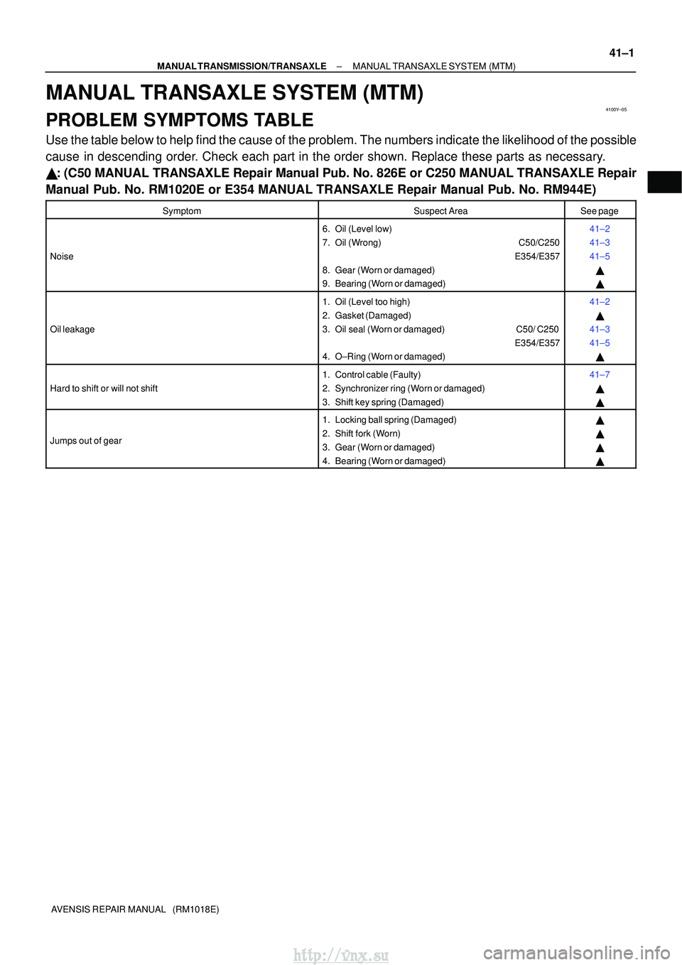
MANUAL TRANSAXLE SYSTEM (MTM)
PROBLEM SYMPTOMS TABLE
Use the table below to help find the cause of the problem. The numbers indi\
cate the likelihood of the possible
cause in descending order. Check each part in the order shown. Replace these parts as necessary.
�: (C50 MANUAL TRANSAXLE Repair Manual Pub. No. 826E or C250 MANUAL TRANS\
AXLE Repair
Manual Pub. No. RM1020E or E354 MANUAL TRANSAXLE Repair Manual Pub. No. RM944E\
)
SymptomSuspect AreaSee page
Noise
6. Oil (Level low)
7. Oil (Wrong) C50/C250
E354/E357
8. Gear (Worn or damaged)
9. Bearing (Worn or damaged)41±2
41±3
41±5 �
�
Oil leakage
1. Oil (Level too high)
2. Gasket (Damaged)
3. Oil seal (Worn or damaged) C50/ C250 E354/E357
4. O±Ring (Worn or damaged)41±2
�
41±3
41±5 �
Hard to shift or will not shift
1. Control cable (Faulty)
2. Synchronizer ring (Worn or damaged)
3. Shift key spring (Damaged)41±7
�
�
Jumps out of gear
1. Locking ball spring (Damaged)
2. Shift fork (Worn)
3. Gear (Worn or damaged)
4. Bearing (Worn or damaged)�
�
�
�
http://vnx.su
Page 1238 of 2234
5000D±14
50±2
±
STEERING COLUMN STEERING SYSTEM
AVENSIS REPAIR MANUAL (RM1018E)
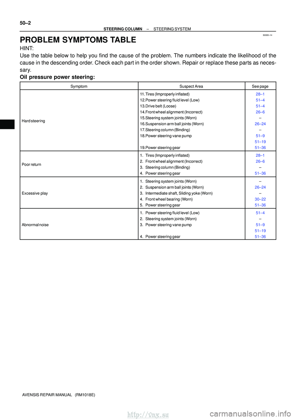
PROBLEM SYMPTOMS TABLE
HINT:
Use the table below to help you find the cause of the problem. The numbers \
indicate the likelihood of the
cause in the descending order. Check each part in the order shown. Repair or replace these parts as n\
eces-
sary.
Oil pressure power steering:
SymptomSuspect AreaSee page
Hard steering
11. Tires (Improperly inflated)
12.Power steering fluid level (Low)
13.Drive belt (Loose)
14.Front wheel alignment (Incorrect)
15.Steering system joints (Worn)
16.Suspension arm ball joints (Worn)
17.Steering column (Binding)
18.Power steering vane pump
19.Power steering gear28±1
51±4
51±4
26±6 ±
26±24 ±
51±9
51±19
51±36
Poor return
1. Tires (Improperly inflated)
2. Front wheel alignment (Incorrect)
3. Steering column (Binding)
4. Power steering gear28±1
26±6 ±
51±36
Excessive play
1. Steering system joints (Worn)
2. Suspension arm ball joints (Worn)
3. Intermediate shaft, Sliding yoke (Worn)
4. Front wheel bearing (Worn)
5. Power steering gear±
26±24 ±
30±22
51±36
Abnormal noise
1. Power steering fluid level (Low)
2. Steering system joints (Worn)
3. Power steering vane pump
4. Power steering gear51±4 ±
51±9
51±19
51±36
http://vnx.su
Page 1244 of 2234
510DE±02
F40449
R11229
NormalAbnormal
R00427
51±4
±
POWER STEERING POWER STEERING SYSTEM
AVENSIS REPAIR MANUAL (RM1018E)
ON±VEHICLE INSPECTION
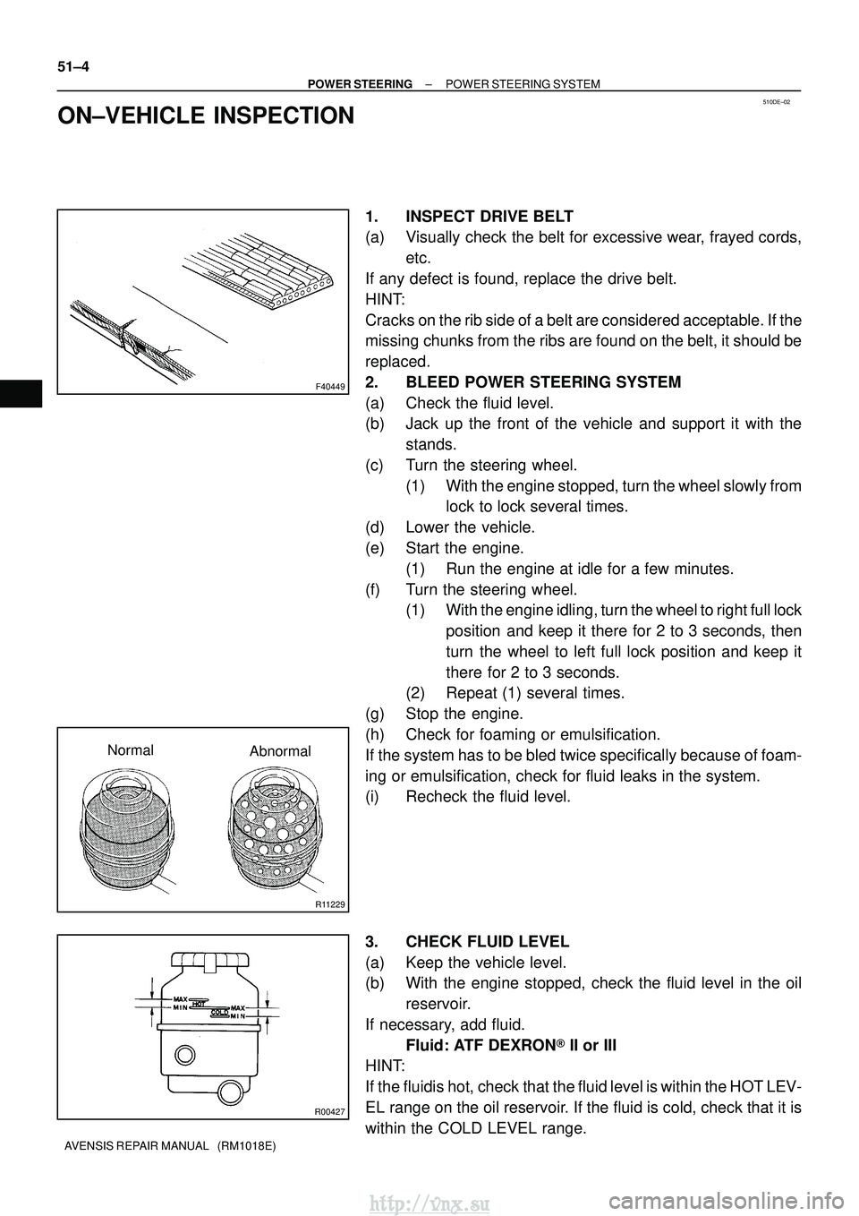
1. INSPECT DRIVE BELT
(a) Visually check the belt for excessive wear, frayed cords, etc.
If any defect is found, replace the drive belt.
HINT:
Cracks on the rib side of a belt are considered acceptable. If the
missing chunks from the ribs are found on the belt, it should be
replaced.
2. BLEED POWER STEERING SYSTEM
(a) Check the fluid level.
(b) Jack up the front of the vehicle and support it with the stands.
(c) Turn the steering wheel. (1) With the engine stopped, turn the wheel slowly fromlock to lock several times.
(d) Lower the vehicle.
(e) Start the engine. (1) Run the engine at idle for a few minutes.
(f) Turn the steering wheel. (1) With the engine idling, turn the wheel to right full lock
position and keep it there for 2 to 3 seconds, then
turn the wheel to left full lock position and keep it
there for 2 to 3 seconds.
(2) Repeat (1) several times.
(g) Stop the engine.
(h) Check for foaming or emulsification.
If the system has to be bled twice specifically because of foam-
ing or emulsification, check for fluid leaks in the system.
(i) Recheck the fluid level.
3. CHECK FLUID LEVEL
(a) Keep the vehicle level.
(b) With the engine stopped, check the fluid level in the oil reservoir.
If necessary, add fluid. Fluid: ATF DEXRON� II or III
HINT:
If the fluidis hot, check that the fluid level is within the HOT LEV-
EL range on the oil reservoir. If the fluid is cold, check that it is
within the COLD LEVEL range.
http://vnx.su
Page 1245 of 2234
R11229
NormalAbnormal
R11786Engine Idling Engine Stopped5 mm (0.20 in.)
or less
±
POWER STEERING POWER STEERING SYSTEM
51±5
AVENSIS REPAIR MANUAL (RM1018E)
(c) Start the engine and run it at idle.
(d) Turn the steering wheel from lock to lock several times to
boost fluid temperature.
Fluid temperature: 80� C (176�F)
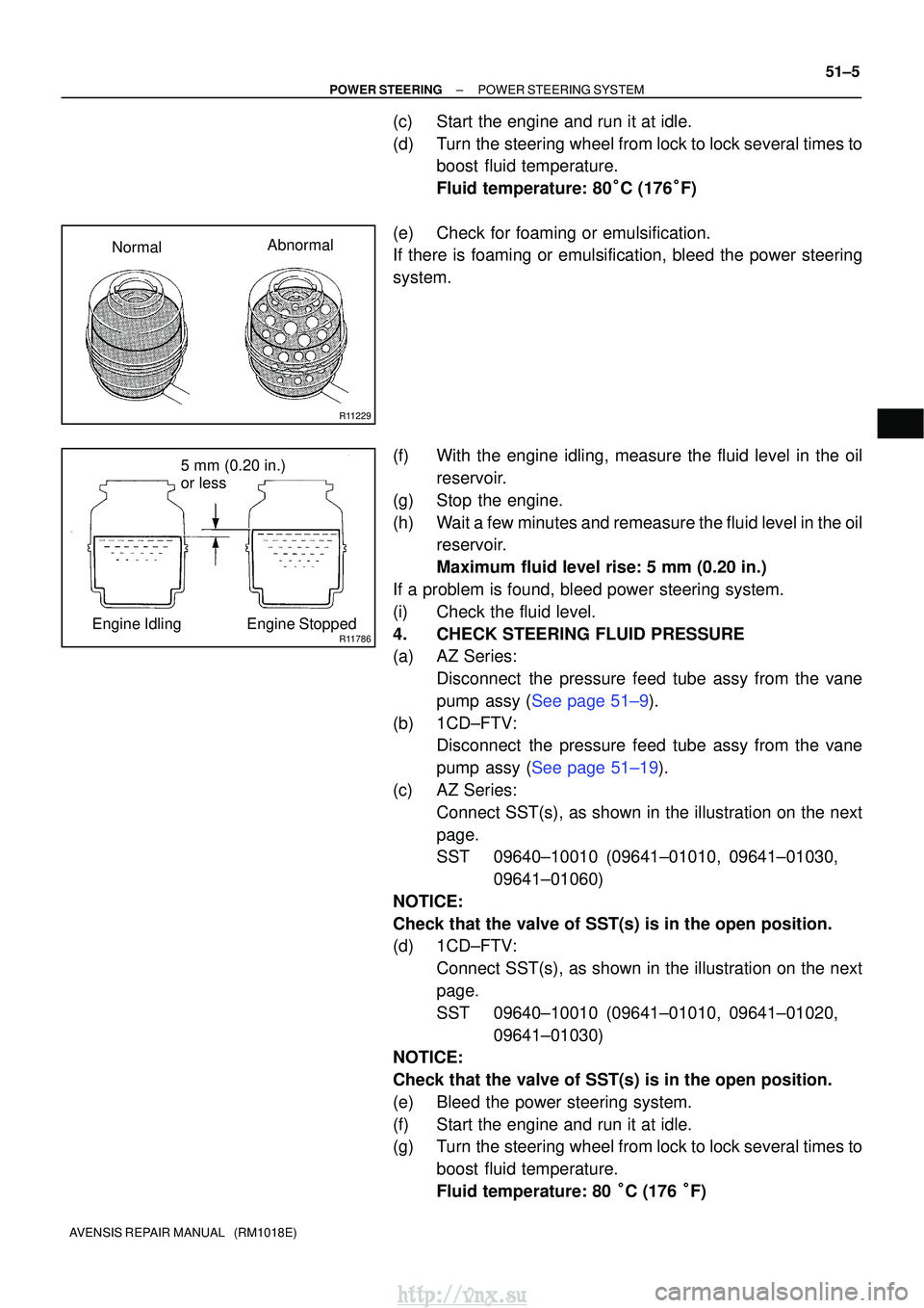
(e) Check for foaming or emulsification.
If there is foaming or emulsification, bleed the power steering
system.
(f) With the engine idling, measure the fluid level in the oil reservoir.
(g) Stop the engine.
(h) Wait a few minutes and remeasure the fluid level in the oil reservoir.
Maximum fluid level rise: 5 mm (0.20 in.)
If a problem is found, bleed power steering system.
(i) Check the fluid level.
4. CHECK STEERING FLUID PRESSURE
(a) AZ Series: Disconnect the pressure feed tube assy from the vane
pump assy (See page 51±9).
(b) 1CD±FTV: Disconnect the pressure feed tube assy from the vane
pump assy (See page 51±19).
(c) AZ Series: Connect SST(s), as shown in the illustration on the next
page.
SST 09640±10010 (09641±01010, 09641±01030, 09641±01060)
NOTICE:
Check that the valve of SST(s) is in the open position.
(d) 1CD±FTV: Connect SST(s), as shown in the illustration on the next
page.
SST 09640±10010 (09641±01010, 09641±01020, 09641±01030)
NOTICE:
Check that the valve of SST(s) is in the open position.
(e) Bleed the power steering system.
(f) Start the engine and run it at idle.
(g) Turn the steering wheel from lock to lock several times to
boost fluid temperature.
Fluid temperature: 80 �C (176 �F)
http://vnx.su
Page 1275 of 2234
������D30361
D30580
B
B
B
A
D30581
Fulcrum
Length
SST(s)
51±26
±
POWER STEERING VANE PUMP ASSY (1CD±FTV)
AVENSIS REPAIR MANUAL (RM1018E)
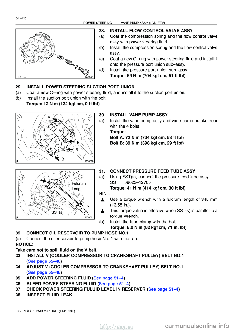
28. INSTALL FLOW CONTROL VALVE ASSY
(a) Coat the compression spring and the flow control valve assy with power steering fluid.
(b) Install the compression spring and the flow control valve assy.
(c) Coat a new O±ring with power steering fluid and install it onto the pressure port union sub±assy.
(d) Install the pressure port union sub±assy. Torque: 69 N �m (704 kgf� cm, 51 ft�lbf)
29. INSTALL POWER STEERING SUCTION PORT UNION
(a) Coat a new O±ring with power steering fluid, and install it to the su\
ction port union.
(b) Install the suction port union with the bolt. Torque: 12 N �m (122 kgf� cm, 9 ft�lbf)
30. INSTALL VANE PUMP ASSY
(a) Install the vane pump assy and vane pump bracket rear with the 4 bolts.
Torque:
Bolt A: 72 N� m (734 kgf�cm, 53 ft�lbf)
Bolt B: 39 N� m (398 kgf�cm, 29 ft�lbf)
31. CONNECT PRESSURE FEED TUBE ASSY
(a) Using SST(s), connect the pressure feed tube assy. SST 09023±12700
Torque: 41 N �m (414 kgf� cm, 30 ft�lbf)
HINT:
�Use a torque wrench with a fulcrum length of 345 mm
(13.58 in.).
�This torque value is effective when SST(s) is parallel to a
torque wrench.
(b) Install the tube clamp with the bolt. Torque: 8.0 N �m (82 kgf �cm, 71 in. �lbf)
32. CONNECT OIL RESERVOIR TO PUMP HOSE NO.1
(a) Connect the oil reservoir to pump hose No. 1 with the clip.
NOTICE:
Take care not to spill fluid on the V belt.
33. INSTALL V (COOLER COMPRESSOR TO CRANKSHAFT PULLEY) BELT NO.1 (See page 55±46)
34. ADJUST V (COOLER COMPRESSOR TO CRANKSHAFT PULLEY) BELT NO.1
(See page 55±46)
35.ADD POWER STEERING FLUID (See page 51±4)
36.BLEED POWER STEERING FLUID (See page 51±4)
37.CHECK POWER STEERING FULUID LEVEL IN RESERVER (See page 51±4)
38. INSPECT FLUID LEAK
http://vnx.su
Page 1285 of 2234
±
POWER STEERING VANE PUMP ASSY (AZ Series)
51±17
AVENSIS REPAIR MANUAL (RM1018E)
37. CONNECT OIL RESERVOIR TO PUMP HOSE NO.1
(a) Connect the oil reservoir to pump hose No.1 with the clip.
NOTICE:
Take care not to spill fluid on the V belt.
38. INSTALL FAN AND GENERATOR V BELT
1AZ±FE: (See page 14±105)
1AZ±FSE: (See page 14±185)
39. INSTALL ENGINE UNDER COVER RH
40. INSTALL FRONT WHEEL RH Torque: 103 N� m (1,050 kgf�cm, 76 ft �lbf)
41.ADD POWER STEERING FLUID (See page 51±4)
42.BLEED POWER STEERING FLUID (See page 51±4)
43.CHECK POWER STEERING FULUID LEVEL IN RESERVER (See page 51±4)
44. INSPECT FLUID LEAK
http://vnx.su
Page 1351 of 2234
I35328
(1)(2)
(3)
(4)
I35327
±
HEATER & AIR CONDITIONER W/PULLEY COMPRESSOR ASSY (1AZ±FE)
55±83
AVENSIS REPAIR MANUAL (RM1018E)
NOTICE:
�When checking the compressor oil level, observe the precautions on the c\
ooler removal/instal-
lation.
�Since compressor oil remains in the pipes of the vehicle, if a new w/pulley c\
ompressor assy
is installed without removing some oil inside, the oil amount becomes ex\
cessive, preventing
heat exchange in the refrigerant cycle and causing refrigerant failure.
�If the remaining oil in the removed w/pulley compressor assy is too smal\
l in volume, check for
oil leakage.
�Be sure to use ND±OIL 8 for compressor oil.
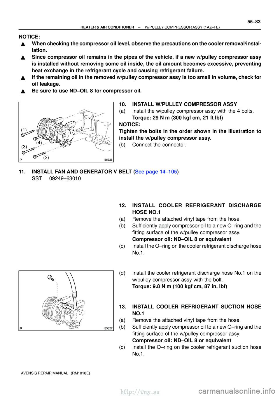
10. INSTALL W/PULLEY COMPRESSOR ASSY
(a) Install the w/pulley compressor assy with the 4 bolts.Torque: 29 N �m (300 kgf� cm, 21 ft�lbf)
NOTICE:
Tighten the bolts in the order shown in the illustration to
install the w/pulley compressor assy.
(b) Connect the connector.
11.INSTALL FAN AND GENERATOR V BELT (See page 14±105) SST 09249±63010
12. INSTALL COOLER REFRIGERANT DISCHARGEHOSE NO.1
(a) Remove the attached vinyl tape from the hose.
(b) Sufficiently apply compressor oil to a new O±ring and the fitting surface of the w/pulley compressor assy.
Compressor oil: ND±OIL 8 or equivalent
(c) Install the O±ring on the cooler refrigerant discharge hose No.1.
(d) Install the cooler refrigerant discharge hose No.1 on the w/pulley compressor assy with the bolt.
Torque: 9.8 N �m (100 kgf� cm, 87 in.�lbf)
13. INSTALL COOLER REFRIGERANT SUCTION HOSE NO.1
(a) Remove the attached vinyl tape from the hose.
(b) Sufficiently apply compressor oil to a new O±ring and the
fitting surface of the w/pulley compressor assy.
Compressor oil: ND±OIL 8 or equivalent
(c) Install the O±ring on the cooler refrigerant suction hose
No.1.
http://vnx.su