Page 910 of 2234
1700E±07
A56466
Recommended Viscosity (SAE)
BEFORE NEXT OIL CHANGE TEMPERATURE RANGE ANTICiPATED416 2738
0 20 40 60 80 100
±29
±20 ±18 ±7
� C
� F 20 W ± 50
15 W ± 40
10 W ± 30
5 W ± 30 PREFERRED
B67536
B67537Oil Pressure Gauge
±
LUBRICATION LUBRICATION SYSTEM (1AZ±FSE)
17±13
AVENSIS REPAIR MANUAL (RM1018E)
LUBRICATION SYSTEM (1AZ±FSE)
ON±VEHICLE INSPECTION
1. CHECK ENGINE OIL LEVEL
(a) After warm up the engine and then 5 minutes after the engine stop, oil l\
evel should be between the
low level and full level marks of the dipstick.
If low, check for leakage and add oil up to the full level mark.
NOTICE:
Do not fill with engine oil above the full level mark.
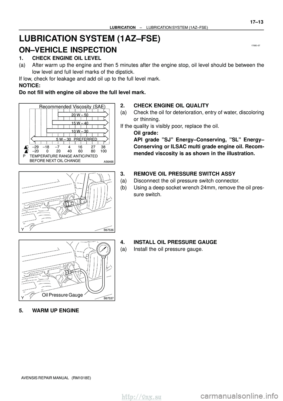
2. CHECK ENGINE OIL QUALITY
(a) Check the oil for deterioration, entry of water, discoloringor thinning.
If the quality is visibly poor, replace the oil. Oil grade:
API grade ºSJº Energy±Conserving, ºSLº Energy±
Conserving or ILSAC multi grade engine oil. Recom-
mended viscosity is as shown in the illustration.
3. REMOVE OIL PRESSURE SWITCH ASSY
(a) Disconnect the oil pressure switch connector.
(b) Using a deep socket wrench 24mm, remove the oil pres- sure switch.
4. INSTALL OIL PRESSURE GAUGE
(a) Install the oil pressure gauge.
5. WARM UP ENGINE
http://vnx.su
Page 912 of 2234
17045±03
A56466
Recommended Viscosity (SAE)
BEFORE NEXT OIL CHANGE TEMPERATURE RANGE ANTICiPATED416 2738
0 20 40 60 80 100
±29
±20 ±18 ±7
� C
� F 20 W ± 50
15 W ± 40
10 W ± 30
5 W ± 30 PREFERRED
B14332
Oil Pressure Switch
B14333
Oil Pressure Gauge
17±20
±
LUBRICATION LUBRICATION SYSTEM (1CD±FTV)
AVENSIS REPAIR MANUAL (RM1018E)
LUBRICATION SYSTEM (1CD±FTV)
ON±VEHICLE INSPECTION
1. CHECK ENGINE OIL LEVEL
(a) After warm up the engine and then 5 minutes after the engine stop, oil l\
evel should be between the low level and full level marks of the dipstick.
If low, check for leakage and add oil up to the full level mark.
NOTICE:
Do not fill with engine oil above the full level mark.
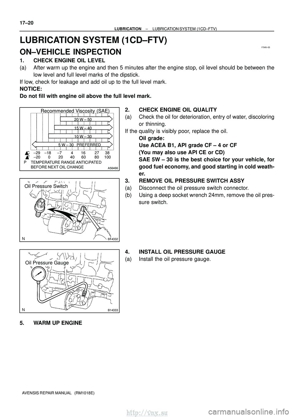
2. CHECK ENGINE OIL QUALITY
(a) Check the oil for deterioration, entry of water, discoloringor thinning.
If the quality is visibly poor, replace the oil. Oil grade:
Use ACEA B1, API grade CF ± 4 or CF
(You may also use API CE or CD)
SAE 5W ± 30 is the best choice for your vehicle, for
good fuel economy, and good starting in cold weath-
er.
3. REMOVE OIL PRESSURE SWITCH ASSY
(a) Disconnect the oil pressure switch connector.
(b) Using a deep socket wrench 24mm, remove the oil pres- sure switch.
4. INSTALL OIL PRESSURE GAUGE
(a) Install the oil pressure gauge.
5. WARM UP ENGINE
http://vnx.su
Page 914 of 2234
1700F±10
A56466
Recommended Viscosity (SAE)
BEFORE NEXT OIL CHANGE TEMPERATURE RANGE ANTICiPATED416 2738
0 20 40 60 80 100
±29
±20 ±18 ±7
� C
� F 20 W ± 50
15 W ± 40
10 W ± 30
5 W ± 30 PREFERRED
Oil Pressure
Switch
A80004
Oil Pressure GaugeOil Pressure Gauge
A50711
±
LUBRICATION LUBRICATION SYSTEM (1ZZ±FE/3ZZ±FE)
17±1
AVENSIS REPAIR MANUAL (RM1018E)
LUBRICATION SYSTEM (1ZZ±FE/3ZZ±FE)
ON±VEHICLE INSPECTION
1. CHECK ENGINE OIL LEVEL
(a) After warm up the engine and then 5 minutes after the engine stop, oil l\
evel should be between the
low level and full level marks of the dipstick.
If low, check for leakage and add oil up to the full level mark.
NOTICE:
Do not fill with engine oil above the full level mark.
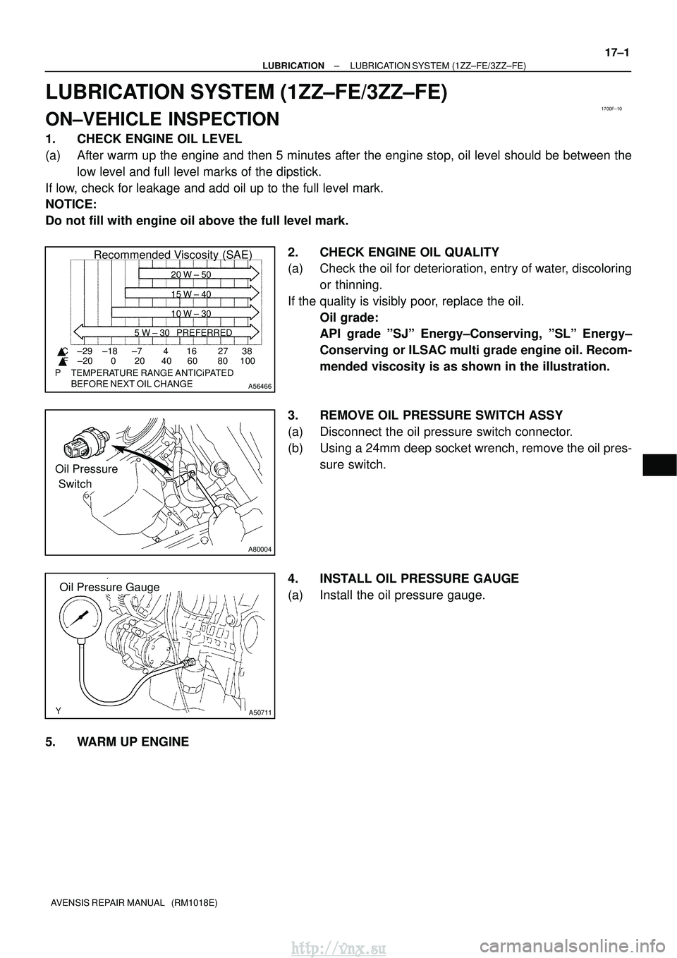
2. CHECK ENGINE OIL QUALITY
(a) Check the oil for deterioration, entry of water, discoloringor thinning.
If the quality is visibly poor, replace the oil. Oil grade:
API grade ºSJº Energy±Conserving, ºSLº Energy±
Conserving or ILSAC multi grade engine oil. Recom-
mended viscosity is as shown in the illustration.
3. REMOVE OIL PRESSURE SWITCH ASSY
(a) Disconnect the oil pressure switch connector.
(b) Using a 24mm deep socket wrench, remove the oil pres- sure switch.
4. INSTALL OIL PRESSURE GAUGE
(a) Install the oil pressure gauge.
5. WARM UP ENGINE
http://vnx.su
Page 932 of 2234
A79173
A79174
A56695
A79175
A56696
±
LUBRICATION OIL PUMP ASSY (1CD±FTV)
17±23
AVENSIS REPAIR MANUAL (RM1018E)
27. REMOVE OIL LEVEL GAGE GUIDE
(a) Remove the bolt which is used to secure the oil level gage
guide to the cylinder block.
(b) Pull out the oil level gage guide together with the oil level gage from the No. 1 oil pan.
(c) Remove the O±ring from the oil level gage guide.
28. REMOVE ENGINE OIL LEVEL SENSOR
(a) Remove the 4 bolts and the level sensor.
NOTICE:
Be careful not to drop the oil level sensor when removing.
29. REMOVE OIL PAN SUB±ASSY NO.2
(a) Remove the 17 bolts and 2 nuts.
(b) Insert the blade of SST between the No. 1 and No. 2 oil pans, and cut off applied sealer and remove the No. 2 oil
pan.
SST 09032±00100
NOTICE:
Be careful not to damage the No. 1 and No. 2 oil pans.
30. REMOVE OIL STRAINER SUB±ASSY
(a) Remove the 2 bolts and 2 nuts, then remove the oil strain- er and the gasket.
http://vnx.su
Page 937 of 2234
A56704
Seal Width
4 to 7 mm
A
B B
A
A79173New O±ring
17±28
±
LUBRICATIONOIL PUMP ASSY(1CD±FTV)
AVENSIS REPAIR MANUAL (RM1018E)
(3)Using a non±residue solvent, clean both the sealing surfaces.
NOTICE:
Do not use a solvent, which will affect the painted surfaces.
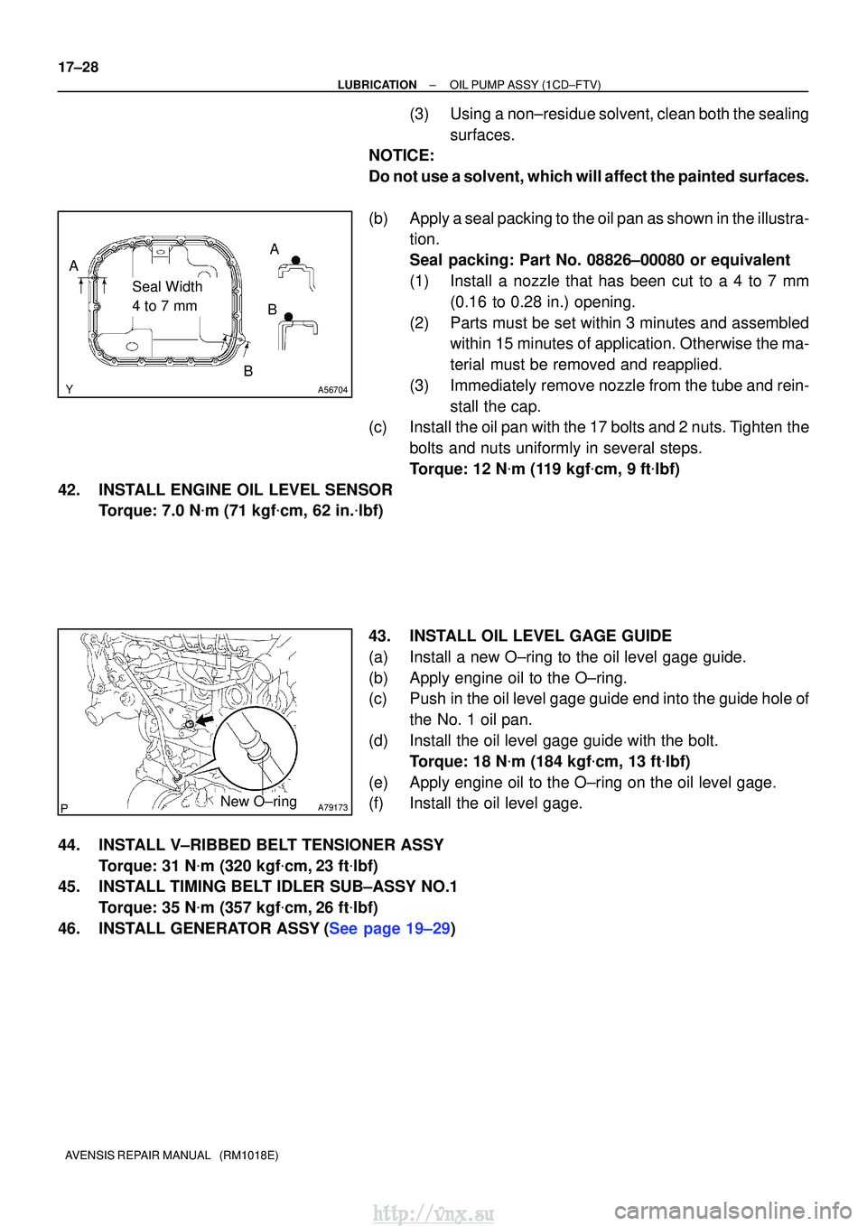
(b)Apply a seal packing to the oil pan as shown in the illustra- tion.
Seal packing: Part No. 08826±00080 or equivalent
(1)Install a nozzle that has been cut to a 4 to 7 mm
(0.16 to 0.28 in.) opening.
(2)Parts must be set within 3 minutes and assembled within 15 minutes of application. Otherwise the ma-
terial must be removed and reapplied.
(3)Immediately remove nozzle from the tube and rein- stall the cap.
(c)Install the oil pan with the 17 bolts and 2 nuts. Tighten the
bolts and nuts uniformly in several steps.
Torque: 12 N �m (119 kgf�cm, 9ft�lbf)
42.INSTALL ENGINE OIL LEVEL SENSOR Torque: 7.0 N �m (71 kgf�cm, 62 in. �lbf)
43.INSTALL OIL LEVEL GAGE GUIDE
(a)Install a new O±ring to the oil level gage guide.
(b)Apply engine oil to the O±ring.
(c)Push in the oil level gage guide end into the guide hole of the No. 1 oil pan.
(d)Install the oil level gage guide with the bolt. Torque: 18 N �m (184 kgf�cm, 13 ft�lbf)
(e)Apply engine oil to the O±ring on the oil level gage.
(f)Install the oil level gage.
44.INSTALL V±RIBBED BELT TENSIONER ASSY Torque: 31 N �m (320 kgf�cm,23 ft�lbf)
45.INSTALL TIMING BELT IDLER SUB±ASSY NO.1
Torque: 35 N �m (357 kgf�cm,26 ft�lbf)
46.INSTALL GENERATOR ASSY(See page 19±29)
http://vnx.su
Page 1112 of 2234
F45419
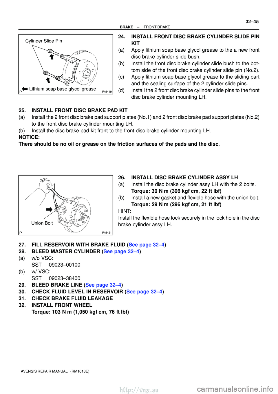
Cylinder Slide Pin
Lithium soap base glycol grease
F45421
Union Bolt
±
BRAKE FRONT BRAKE
32±45
AVENSIS REPAIR MANUAL (RM1018E)
24. INSTALL FRONT DISC BRAKE CYLINDER SLIDE PIN
KIT
(a) Apply lithium soap base glycol grease to the a new front
disc brake cylinder slide bush.
(b) Install the front disc brake cylinder slide bush to the bot- tom side of the front disc brake cylinder slide pin (No.2).
(c) Apply lithium soap base glycol grease to the sliding part
and the sealing surface of the 2 cylinder slide pins.
(d) Install the 2 front disc brake cylinder slide pins to the front disc brake cylinder mounting LH.
25. INSTALL FRONT DISC BRAKE PAD KIT
(a) Install the 2 front disc brake pad support plates (No.1) and 2 front disc bra\
ke pad support plates (No.2) to the front disc brake cylinder mounting LH.
(b) Install the disc brake pad kit front to the front disc brake cylinder mo\
unting LH.
NOTICE:
There should be no oil or grease on the friction surfaces of the pads an\
d the disc.
26. INSTALL DISC BRAKE CYLINDER ASSY LH
(a) Install the disc brake cylinder assy LH with the 2 bolts.Torque: 30 N �m (306 kgf� cm, 22 ft�lbf)
(b) Install a new gasket and flexible hose with the union bolt.
Torque: 29 N� m (296 kgf�cm, 21 ft�lbf)
HINT:
Install the flexible hose lock securely in the lock hole in the disc
brake cylinder assy LH.
27.FILL RESERVOIR WITH BRAKE FLUID (See page 32±4)
28.BLEED MASTER CYLINDER (See page 32±4)
(a) w/o VSC: SST 09023±00100
(b) w/ VSC: SST 09023±38400
29.BLEED BRAKE LINE (See page 32±4)
30.CHECK FLUID LEVEL IN RESERVOIR (See page 32±4)
31. CHECK BRAKE FLUID LEAKAGE
32. INSTALL FRONT WHEEL
Torque: 103 N� m (1,050 kgf�cm, 76 ft �lbf)
http://vnx.su
Page 1172 of 2234
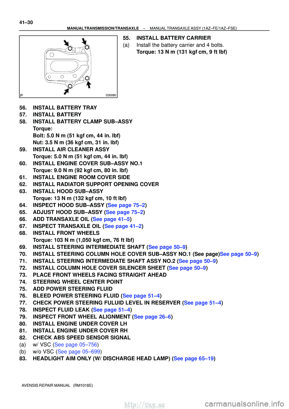
D30080
41±30
±
MANUAL TRANSMISSION/TRANSAXLE MANUAL TRANSAXLE ASSY (1AZ±FE/1AZ±FSE)
AVENSIS REPAIR MANUAL (RM1018E)
55. INSTALL BATTERY CARRIER
(a) Install the battery carrier and 4 bolts. Torque: 13 N �m (131 kgf� cm, 9 ft�lbf)
56. INSTALL BATTERY TRAY
57. INSTALL BATTERY
58. INSTALL BATTERY CLAMP SUB±ASSY Torque:
Bolt: 5.0 N �m (51 kgf �cm, 44 in. �lbf)
Nut: 3.5 N� m (36 kgf�cm, 31 in. �lbf)
59. INSTALL AIR CLEANER ASSY Torque: 5.0 N �m (51 kgf �cm, 44 in. �lbf)
60. INSTALL ENGINE COVER SUB±ASSY NO.1 Torque: 9.0 N �m (92 kgf �cm, 80 in. �lbf)
61. INSTALL ENGINE ROOM COVER SIDE
62. INSTALL RADIATOR SUPPORT OPENING COVER
63. INSTALL HOOD SUB±ASSY Torque: 13 N �m (132 kgf� cm, 10 ft�lbf)
64.INSPECT HOOD SUB±ASSY (See page 75±2)
65.ADJUST HOOD SUB±ASSY (See page 75±2)
66.ADD TRANSAXLE OIL (See page 41±5)
67.INSPECT TRANSAXLE OIL (See page 41±2)
68. INSTALL FRONT WHEELS
Torque: 103 N� m (1,050 kgf�cm, 76 ft �lbf)
69.INSTALL STEERING INTERMEDIATE SHAFT (See page 50±9)
70.INSTALL STEERING COLUMN HOLE COVER SUB±ASSY NO.1 (See page)See page 50±9)
71.INSTALL STEERING INTERMEDIATE SHAFT ASSY NO.2 (See page 50±9)
72.INSTALL COLUMN HOLE COVER SILENCER SHEET (See page 50±9)
73. PLACE FRONT WHEELS FACING STRAIGHT AHEAD
74. STEERING WHEEL CENTER POINT
75. ADD POWER STEERING FLUID
76.BLEED POWER STEERING FLUID (See page 51±4)
77.CHECK POWER STEERING FULUID LEVEL IN RESERVER (See page 51±4)
78.INSPECT FLUID LEAK (See page 51±4)
79.INSPECT FRONT WHEEL ALIGNMENT (See page 26±6)
80. INSTALL ENGINE UNDER COVER LH
81. INSTALL ENGINE UNDER COVER RH
82. CHECK ABS SPEED SENSOR SIGNAL
(a)w/ VSC (See page 05±756)
(b)w/o VSC (See page 05±699)
83.HEADLIGHT AIM ONLY (W/ DISCHARGE HEAD LAMP) (See page 65±19)
http://vnx.su
Page 1182 of 2234
41±40
±
MANUAL TRANSMISSION/TRANSAXLE MANUAL TRANSAXLE ASSY (1CD±FTV)
AVENSIS REPAIR MANUAL (RM1018E)
75. INSTALL HOOD SUB±ASSY Torque: 13 N �m (133 kgf� cm, 10 ft�lbf)
76.INSPECT HOOD SUB±ASSY (See page 75±2)
77.ADJUST HOOD SUB±ASSY (See page 75±2)
78.ADD TRANSAXLE OIL (See page 41±5)
79.INSPECT TRANSAXLE OIL (See page 41±2)
80. ADD POWER STEERING FLUID
81.BLEED POWER STEERING FLUID (See page 51±4)
82.CHECK POWER STEERING FULUID LEVEL IN RESERVER (See page 51±4)
83.INSPECT FLUID LEAK (See page 51±4)
84. INSTALL FRONT WHEELS Torque: 103 N� m (1,050 kgf�cm, 76 ft �lbf)
85.INSPECT FRONT WHEEL ALIGNMENT (See page 26±6)
86. INSTALL ENGINE UNDER COVER RH
87. INSTALL ENGINE UNDER COVER LH
88. CHECK ABS SPEED SENSOR SIGNAL
(a)w/ VSC (See page 05±756)
(b)w/o VSC (See page 05±699)
89.HEADLIGHT AIM ONLY (W/ DISCHARGE HEAD LAMP) (See page 65±19)
http://vnx.su