Page 639 of 2234

14±127
AVENSIS REPAIR MANUAL (RM1018E)
63.SEPARATE VANE PUMP ASSY
(a)Disconnect the PS oil pressure switch connector.
(b)Remove the")
A77402SST
A56446
±
ENGINE MECHANICALPARTIAL ENGINE ASSY(1AZ±FE)
14±127
AVENSIS REPAIR MANUAL (RM1018E)
63.SEPARATE VANE PUMP ASSY
(a)Disconnect the PS oil pressure switch connector.
(b)Remove the 2 bolts and separate the vane pump from the engine.
64.REMOVE STARTER ASSY (See page 19±12)
65.REMOVE FRONT SUSPENSION CROSSMEMBER W/CENTER MEMBER
(a)Remove the through bolt and nut from the engine mounting insulator FR.
(b)Remove the through bolt and nut from the engine mounting insulator RR.
66.REMOVE FRONT DRIVE SHAFT ASSY LH (See page 30±6)
67.REMOVE FRONT DRIVE SHAFT ASSY RH (See page 30±6)
68.REMOVE MANUAL TRANSAXLE ASSY (M/T TRANSAXLE) (See page 41±24)
69.REMOVE AUTOMATIC TRANSAXLE ASSY (A/T TRANSAXLE) (See page 40±25)
70.REMOVE CLUTCH COVER ASSY (M/T TRANSAXLE) (See page 42±26)
71.REMOVE CLUTCH DISC ASSY (M/T TRANSAXLE) (See page 42±26)
72. REMOVE DRIVE PLATE AND RING GEAR ORFLYWHEEL
(a) Using SST, fix the crankshaft pulley and remove the drive plate and ring gear or flywheel.
SST 09213±54015 (91651±60855), 09330±00021
73. REMOVE CAMSHAFT TIMING OIL CONTROL VALVE ASSY (W/ VVT±i)
(a) Remove a bolt, O±ring and the camshaft timing oil control valve. 74. REMOVE INTAKE MANIFOLD
(a) Remove the 5 bolts and 2 nuts, and then remove the in-take manifold.
75. REMOVE VENTILATION HOSE
76. REMOVE VENTILATION HOSE NO.2
77. REMOVE ENGINE WIRE
78. REMOVE INTAKE MANIFOLD INSULATOR NO.1
79. REMOVE OIL LEVEL GAGE SUB±ASSY
80. REMOVE OIL LEVEL GAGE GUIDE
81. REMOVE MANIFOLD CONVERTER INSULATOR NO.1
(a) Remove the 4 bolts and the manifold converter insulator No. 1.
http://vnx.su
Page 642 of 2234

AVENSIS REPAIR MANUAL (RM1018E)
(b) Install the No. 1 and No. 2 exhaust manifold stays with the 2 bolts and 2 nuts.")
A52499
A56446
A77333SST
14±130
±
ENGINE MECHANICAL PARTIAL ENGINE ASSY (1AZ±FE)
AVENSIS REPAIR MANUAL (RM1018E)
(b) Install the No. 1 and No. 2 exhaust manifold stays with the 2 bolts and 2 nuts.
Torque: 44 N �m (449 kgf� cm, 32 ft�lbf)
105. INSTALL MANIFOLD CONVERTER INSULATOR NO.1 Torque: 12 N �m (122 kgf� cm, 9.0 ft�lbf)
106. INSTALL OIL LEVEL GAGE GUIDE
(a) Apply a light coat of engine oil to the O±ring, install it to the oil\
level gauge guide.
(b) Install the oil level gauge and guide with the bolt. Torque: 9.0 N �m (92 kgf �cm, 80 in. �lbf)
107. INSTALL INTAKE MANIFOLD
(a) Install a new gasket and the intake manifold with the 5 bolts and 2 nuts.
Torque: 30 N �m (306 kgf� cm, 22 ft�lbf)
108. INSTALL CAMSHAFT TIMING OIL CONTROL VALVE ASSY (W/ VVT±i)
(a) Apply light coat of engine oil to the new O±ring and install it to th\
e camshaft timing oil control valve.
(b) Install the camshaft oil control valve with the bolt. Torque: 9.0 N �m (92 kgf �cm, 79 in. �lbf)
109. I N S TA L L D R I V E P L AT E A N D R I N G G E A R O R FLYWHEEL
(a) Hold the crankshaft with SST.
SST 09213±54015 (91651±60855), 09330±00021
Adhesive:
Part No. 08833±00070, THREE BOND or equivalent
http://vnx.su
Page 655 of 2234
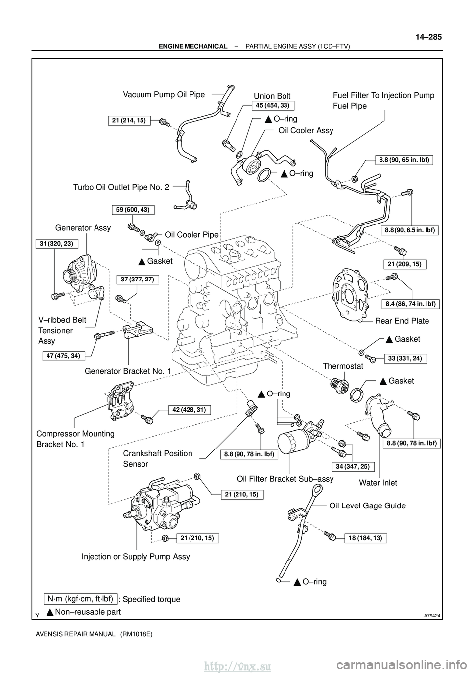
A79424
N´m (kgf´cm, ft´lbf): Specified torque
� Non±reusable part
8.8 (90, 65 in. �lbf)
8.8 (90, 6.5 in. �lbf)
8.4 (86, 74 in. �lbf)
21 (209, 15)
8.8 (90, 78 in. �lbf)
34 (347, 25)
18 (184, 13)21 (210, 15)
21 (210, 15)
42 (428, 31)
37 (377, 27)
59 (600, 43)
21 (214, 15)
45 (454, 33)
� O±ring
� O±ring
� Gasket
� O±ring
� O±ring
Vacuum Pump Oil Pipe
Union Bolt
Oil Cooler Assy Fuel Filter To Injection Pump
Fuel Pipe
Rear End Plate
Crankshaft Position
Sensor
Thermostat Water Inlet
Oil Level Gage Guide
Oil Filter Bracket Sub±assy
Injection or Supply Pump Assy
Compressor Mounting
Bracket No. 1
Generator Bracket No. 1
V±ribbed Belt
Tensioner
Assy Generator Assy
Oil Cooler Pipe
� Gasket
Turbo Oil Outlet Pipe No. 2
31 (320, 23)
� Gasket
33 (331, 24)
8.8 (90, 78 in. �lbf)
47 (475, 34)
±
ENGINE MECHANICAL PARTIAL ENGINE ASSY (1CD±FTV)
14±285
AVENSIS REPAIR MANUAL (RM1018E)
http://vnx.su
Page 664 of 2234

AVENSIS REPAIR MANUAL (RM1018E)
93.REMOVE INTAKE MANIFOLD INSULATOR NO.1
(a)Remove the 2 bolts and the intake manifold")
A79150
A61175
A09671
14±294
±
ENGINE MECHANICALPARTIAL ENGINE ASSY(1CD±FTV)
AVENSIS REPAIR MANUAL (RM1018E)
93.REMOVE INTAKE MANIFOLD INSULATOR NO.1
(a)Remove the 2 bolts and the intake manifold insulator.
94.REMOVE COMMON RAIL ASSY (See page 11±78) 95.REMOVE POWER STEERING IDLE PULLEY
BRACKET
(a)Remove the 3 bolts and the idle pulley bracket.
96.REMOVE INTAKE MANIFOLD
(a)Remove the 2 bolts and the wiring harness clamp bracket.
(b)Remove the 8 bolts and 2 nuts, and then remove the in- take manifold and the gasket.
97.REMOVE INJECTION PUMP DRIVE PULLEY (See page 11±69) SST 09960±10010 (09962±01000, 09963±01000)
98. REMOVE TIMING BELT NO.3 COVER
(a) Remove the 2 bolts and 2 seal washers, and then remove the timing belt c\
over.
99.REMOVE OIL LEVEL GAGE GUIDE (See page 17±22)
100.REMOVE INJECTION OR SUPPLY PUMP ASSY (See page 11±69)
101. REMOVE COMPRESSOR MOUNTING BRACKET NO.1
(a) Remove the 4 bolts and the compressor mounting bracket.
102. REMOVE WATER INLET
(a) Remove the 2 bolts and the water inlet.
103. REMOVE THERMOSTAT
104. REMOVE OIL COOLER PIPE
(a) Remove the union bolt, the oil cooler pipe and the gasket.
105. REMOVE FUEL FILTER TO INJECTION PUMP FUEL PIPE
(a) Remove the 3 bolts and nut, and then detach the fuel pipe.
http://vnx.su
Page 665 of 2234

14±295
AVENSIS REPAIR MANUAL (RM1018E)
106.REMOVE CRANKSHAFT POSITION SENSOR
(a)Remove the bolt and the crankshaft position senso")
A79173New O±Ring
±
ENGINE MECHANICALPARTIAL ENGINE ASSY(1CD±FTV)
14±295
AVENSIS REPAIR MANUAL (RM1018E)
106.REMOVE CRANKSHAFT POSITION SENSOR
(a)Remove the bolt and the crankshaft position sensor.
107.REMOVE CAMSHAFT POSITION SENSOR
(a)Remove the bolt and the camshaft position sensor.
108.REMOVE ENGINE COOLANT TEMPERATURE SENSOR
109.REPLACE PARTIAL ENGINE ASSY
110.INSTALL ENGINE COOLANT TEMPERATURE SENSOR
Torque: 20 N �m (204 kgf�cm,15 ft�lbf)
111.INSTALL CAMSHAFT POSITION SENSOR Torque: 8.8 N �m (90 kgf�cm,78 in. �lbf)
112.INSTALL CRANKSHAFT POSITION SENSOR Torque: 8.8 N �m (90 kgf�cm,78 in. �lbf)
113.INSTALL FUEL FILTER TO INJECTION PUMP FUEL PIPE Torque:
8.8 N�m (90 kgf �cm,78 ft�lbf) for M6 and Nut
21 N�m (209 kgf�cm,15 ft�lbf) for M8
114.INSTALL OIL COOLER PIPE
(a)Install 2 new gaskets and the oil cooler pipe with the union bolt. Torque: 59 N �m (600 kgf�cm,43 ft�lbf)
115.INSTALL THERMOSTAT (See page 16±50)
116.INSTALL WATER INLET (See page 16±50)
117. INSTALL COMPRESSOR MOUNTING BRACKET NO.1
Torque: 42 N �m (428 kgf� cm, 31 ft�lbf)
118. INSTALL INJECTION OR SUPPLY PUMP ASSY Torque: 21 N �m (214 kgf� cm, 15 ft�lbf)
119. INSTALL OIL LEVEL GAGE GUIDE
(a) Install a new O±ring to the oil level gage guide.
(b) Apply engine oil to the O±ring.
(c) Push in the oil level gage guide end into the guide hole of the No. 1 oil pan.
(d) Install the oil level gage guide with the bolt. Torque: 18 N �m (184 kgf� cm, 13 ft�lbf)
(e) Apply engine oil to the O±ring on the oil level gage.
(f) Install the oil level gage.
120. INSTALL TIMING BELT NO.3 COVER Torque: 7.4 N �m (75 kgf �cm, 65 in. �lbf)
121.INSTALL INJECTION PUMP DRIVE PULLEY (See page 11±69)
SST 09960±10010 (09962±01000, 09963±01000)
122. INSTALL INTAKE MANIFOLD
(a) Install a new gasket and the intake manifold with the 8 bolts and 2 nuts\
. Torque: 21 N �m (214 kgf� cm, 15 ft�lbf)
(b) Install the wiring harness clamp bracket with the 2 bolts.
Torque: 3.9 to 6.9 N� m (40 to 70 kgf�cm, 35 to 61 in.� lbf)
http://vnx.su
Page 674 of 2234
14±304
±
ENGINE MECHANICAL PARTIAL ENGINE ASSY (1CD±FTV)
AVENSIS REPAIR MANUAL (RM1018E)
191. INSTALL AIR CLEANER ASSY Torque: 7.0 N �m (71 kgf �cm, 62 in. �lbf)
192. INSTALL ENGINE COVER NO.1
Torque: 8.0 N �m (82 kgf �cm, 71 in. �lbf)
193.BLEED CLUTCH PIPE LINE (See page 42±17)
194. INSTALL FRONT WHEELS Torque: 103 N� m (1,050 kgf�cm, 76 ft �lbf)
195. ADD MANUAL TRANSAXLE OIL
196. ADD ENGINE OIL
197.ADD ENGINE COOLANT (See page 16±44)
198. CHECK CLUTCH FLUID LEAKAGE
199. CHECK FLUID LEVEL IN RESERVOIR
200. CHECK BRAKE FLUID LEAKAGE
201. CHECK FOR ENGINE OIL LEAKS
202.CHECK FOR FUEL LEAKS (See page 11±60)
203.CHECK FOR ENGINE COOLANT LEAKS (See page 16±44)
204. CHECK FOR EXHAUST GAS LEAKS
205.INSPECT AND ADJUST FRONT WHEEL ALIGNMENT (See page 26±6)
206.INSPECT ENGINE IDLE SPEED (See page 14±266)
207.CHECK ABS SPEED SENSOR SIGNAL (See page 05±756)
http://vnx.su
Page 681 of 2234
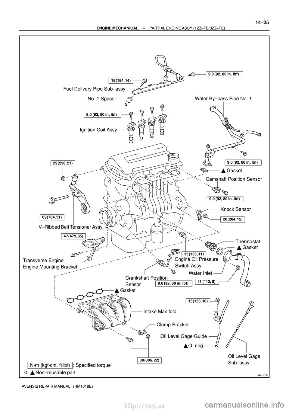
A76706
Fuel Delivery Pipe Sub±assyNo. 1 Spacer
Ignition Coil Assy
V±Ribbed Belt Tensioner Assy
� Gasket
Intake ManifoldClamp BracketOil Level Gage Guide � O±ring
Oil Level Gage
Sub±assy
Crankshaft Position
Sensor �
Gasket
Thermostat
Knock Sensor
Engine Oil Pressure
Switch Assy Camshaft Position Sensor
�
Gasket
Water By±pass Pipe No. 1
�
Non±reusable part
N´m (kgf´cm, ft´lbf) : Specified torque
Water Inlet
19 (194, 14)
9.0 (92, 80 in.� lbf)
9.0 (92, 80 in.�lbf)
9.0 (92, 80 in. �lbf)
9.0 (92, 80 in. �lbf)29 (296, 21)
69 (704, 51)
15 (153, 11)
20 (204, 15)
11 (112, 8)
30 (306, 22)
9.0 (92, 80 in.� lbf)
Transverse Engine
Engine Mounting Bracket
13 (133, 10)
47 (479, 35)
±
ENGINE MECHANICAL PARTIAL ENGINE ASSY (1ZZ±FE/3ZZ±FE)
14±25
AVENSIS REPAIR MANUAL (RM1018E)
http://vnx.su
Page 690 of 2234
A76713
A64023
A79363
A64026
14±34
±
ENGINE MECHANICAL PARTIAL ENGINE ASSY (1ZZ±FE/3ZZ±FE)
AVENSIS REPAIR MANUAL (RM1018E)
(b) Remove the 2 nuts which are used to secure the engine wire.
(c) Remove the 4 bolts and the 4 ignition coils.
69. REMOVE FUEL DELIVERY PIPE SUB±ASSY (See page 11±11)
70. REMOVE INTAKE MANIFOLD
(a) Disconnect the 2 water hoses from the throttle body.
(b) Disconnect the ventilation hose and the ventilation hose No. 2 from the cylinder head cover.
(c) Disconnect the vacuum hose from the water by±pass
pipe No. 1.
(d) Remove the 4 bolts, 2 nuts and 2 wire brackets,then re- move the intake manifold and the throttle body assembly.
(e) Remove the gasket from the intake manifold and the
throttle body assembly.
71. REMOVE OIL LEVEL GAGE SUB±ASSY
(a) Remove the oil level gage from the oil level gage guide.
72. REMOVE OIL LEVEL GAGE GUIDE
(a) Disconnect the crank shaft position sensor cramp.
(b) Remove the bolt and the oil level gage guide.
http://vnx.su

AVENSIS REPAIR MANUAL (RM1018E)
(b) Remove the 2 nuts which are used to secure the engine wire.
(c) Remo")