2003 TOYOTA AVENSIS oil level
[x] Cancel search: oil levelPage 2137 of 2234
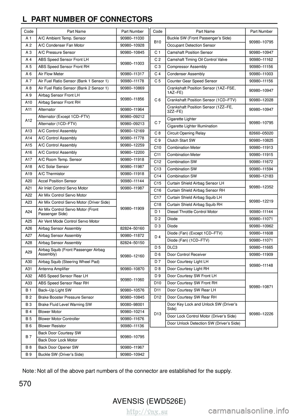
L PART NUMBER OF CONNECTORS
CodePart Name Part NumberCodePart Name Part Number
AVENSIS (EWD526E)
Note : Not all of the above part numbers of the connector are established for t\
he supply.
570
A 1A/C Ambient Temp. Sensor90980–11030
A 2A/C Condenser Fan Motor90980–10928
A 3A/C Pressure Sensor90980–10845
A 4ABS Speed Sensor Front LH
A 5ABS Speed Sensor Front RH90980–11003
A 6Air Flow Meter90980–11317
A 7Air Fuel Ratio Sensor (Bank 1 Sensor 1)90980–11178
A 8Air Fuel Ratio Sensor (Bank 2 Sensor 1)90980–10869
A 9Airbag Sensor Front LH
A10Airbag Sensor Front RH90980–11856
A11Alternator90980–11964
Alternator (Except 1CD–FTV)90980–09212A12Alternator (1CD–FTV)90980–09213
A13A/C Control Assembly90980–12169
A14A/C Control Assembly90980–11778
A15A/C Control Assembly90980–12259
A16A/C Control Assembly90980–12200
A17A/C Room Temp. Sensor90980–11918
A18A/C Solar Sensor90980–11987
A19A/C Thermistor90980–11918
A20Accel Position Sensor90980–11144
A21Air Inlet Control Servo Motor90980–11987
A22Air Mix Control Servo Motor
A23Air Mix Control Servo Motor (Driver Side)
A24Air Mix Control Servo Motor (Front
Passenger Side)90980–11909
A25Air Vent Mode Control Servo Motor
A26Airbag Sensor Assembly82824–50160
A27Airbag Sensor Assembly90980–11872
A28Airbag Sensor Assembly82824–50150
A29Airbag Squib (Front Passenger Airbag
Assembly)
90980–12160
A30Airbag Squib (Steering Wheel Pad)
A31Antenna Amplifier90980–10870
A32ABS Speed Sensor Rear LH
A33ABS Speed Sensor Rear RH90980–11060
B 1Back–Up Light SW90980–10576
B 2Brake Booster Pressure Sensor90980–10845
B 3Brake Fluid Level Warning SW90080–98001
B 4Blower Motor90980–10214
B 5Blower Motor Controller90980–11676
B 6Blower Resistor90980–11136
Back Door Courtesy SWB 7Back Door Lock Motor90980–10795
B 8Back Door Opener SW90980–11967
B 9Buckle SW (Driver’s Side)90980–10942
Buckle SW (Front Passenger’s Side)B10Occupant Detection Sensor90980–10795
C 1Camshaft Position Sensor90980–10947
C 2Camshaft Timing Oil Control Valve90980–11162
C 3Compressor Assembly90980–11156
C 4Condenser Assembly90980–11003
C 5Counter Gear Speed Sensor90980–11156
Crankshaft Position Sensor (1AZ–FSE,
1AZ–FE)90980–10947
C 6Crankshaft Position Sensor (1CD–FTV)90980–12028
Crankshaft Position Sensor (1ZZ–FE,
3ZZ–FE)90980–10947
Cigarette LighterC 7Cigarette Lighter Illumination90980–10795
C 8Circuit Opening Relay82660–05020
C 9Clutch Start SW90980–10825
C10Combination Meter90980–11913
C11Combination Meter90980–11915
C12Combination SW90980–11672
C13Combination SW90980–11594
C14Combination SW90980–12183
C15Curtain Shield Airbag Sensor LH
C16Curtain Shield Airbag Sensor RH90980–12352
C17Curtain Shield Airbag Squib LH
C18Curtain Shield Airbag Squib RH90980–12219
D 1Diesel Throttle Control Motor90980–11144
D 2Diode90980–11071
D 3Diode90980–10962
Diode (Fan) (Except 1CD–FTV)90980–11608D 4Diode (Fan) (1CD–FTV)90980–11071
D 5DLC390980–11665
D 6Door Control Receiver90980–11909
D 7Door Courtesy Light LH
D 8Door Courtesy Light RH90980–11148
D 9Door Courtesy SW Front LH
D10Door Courtesy SW Front RH
D11Door Courtesy SW Rear LH90980–10871
D12Door Courtesy SW Rear RH
Door Key Lock and Unlock SW (Driver’s
Side)
D13Door Lock Control Motor (Driver’s Side)90980–12226
Door Unlock Detection SW (Driver’s Side)
http://vnx.su
Page 2138 of 2234
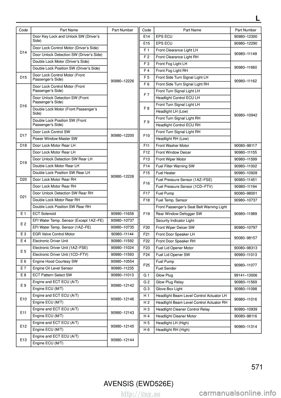
L
CodePart Name Part NumberCodePart Name Part Number
AVENSIS (EWD526E) 571
Door Key Lock and Unlock SW (Driver
’s
Side)
Door Lock Control Motor (Driver ’s Side)D14Door Unlock Detection SW (Driver ’s Side)
Double Lock Motor (Driver ’s Side)
Double Lock Position SW (Driver ’s Side)
D15Door Lock Control Motor (Front
Passenger ’s Side)
90980–12226
Door Lock Control Motor (Front
Passenger ’s Side)
Door Unlock Detection SW (Front
Passenger ’s Side)
D16Double Lock Motor (Front Passenger ’s
Side)
Double Lock Position SW (Front
Passenger ’s Side)
Door Lock Control SWD17Power Window Master SW90980–12200
D18Door Lock Motor Rear LH
Door Lock Motor Rear LH
Door Unlock Detection SW Rear LHD19Double Lock Motor Rear LH
Double Lock Position SW Rear LH
D20Door Lock Motor Rear RH90980–12226
Door Lock Motor Rear RH
Door Unlock Detection SW Rear RHD21Double Lock Motor Rear RH
Double Lock Position SW Rear RH
E 1ECT Solenoid90980–11658
EFI Water Temp. Sensor (Except 1AZ–FE)90980–10737E 2EFI Water Temp. Sensor (1AZ–FE)90980–10735
E 3EGR Valve Control Motor90980–11144
E 4Electronic Driver Unit90980–11592
Electronic Driver Unit (1AZ–FSE)90980–11024E 5Electronic Driver Unit (1CD–FTV)90980–11593
E 6Engine Hood Courtesy SW90980–10554
E 7Engine Oil Level Sensor90980–11235
E 8ECT Pattern Select SW90980–11013
Engine and ECT ECU (A/T)E 9Engine ECU (M/T)90980–12142
Engine and ECT ECU (A/T)E10Engine ECU (M/T)90980–12146
Engine and ECT ECU (A/T)E11Engine ECU (M/T)90980–12143
Engine and ECT ECU (A/T)E12Engine ECU (M/T)90980–12145
Engine and ECT ECU (A/T)E13Engine ECU (M/T)90980–12144
E14EPS ECU90980–12300
E15EPS ECU90980–12290
F 1Front Clearance Light LH
F 2Front Clearance Light RH90980–11149
F 3Front Fog Light LH
F 4Front Fog Light RH90980–11660
F 5Front Side Turn Signal Light LH
F 6Front Side Turn Signal Light RH90980–11162
Front Turn Signal Light LHF 7Headlight Control ECU LH
Front Turn Signal Light LHF 8Headlight LH (Low)
Front Turn Signal Light RH90980–10942
F 9Headlight Control ECU RH
Front Turn Signal Light RHF10Headlight RH (Low)
F11Front Washer Motor90080–98117
F12Front Window Deicer90980–11155
F13Front Wiper Motor90980–11599
F14Fuel Filter Warning SW90980–11002
F15Fuel Heater90980–10928
Fuel Pressure Sensor (1AZ–FSE)90980–11451F16Fuel Pressure Sensor (1CD–FTV)90980–11194
F17Fuel Pump90080–98001
F18Fuel Temp. Sensor90980–10737
Front Passenger ’s Seat Belt Warning Light
F19Rear Window Defogger SW90980–11989
Security Indicator Light
F20Front Wiper Deicer SW90980–10797
F21Front Door Speaker LH
F22Front Door Speaker RH90080–98157
F23Fuel Lid Opener Motor90080–98313
F24Fuel Lid Opener SW90980–11013
Fuel PumpF25Fuel Sender90980–11077
G 1Glow Plug99141–13006
G 2Glow Plug Relay90980–11569
G 3Glove Box Light90980–11098
H 1Headlight Beam Level Control Actuator LH
H 2Headlight Beam Level Control Actuator RH90980–11016
H 3Headlight Cleaner Control Relay90980–10939
H 4Headlight Cleaner Motor90080–98116
H 5Headlight LH (High)
H 6Headlight RH (High)90980–11314
http://vnx.su
Page 2139 of 2234
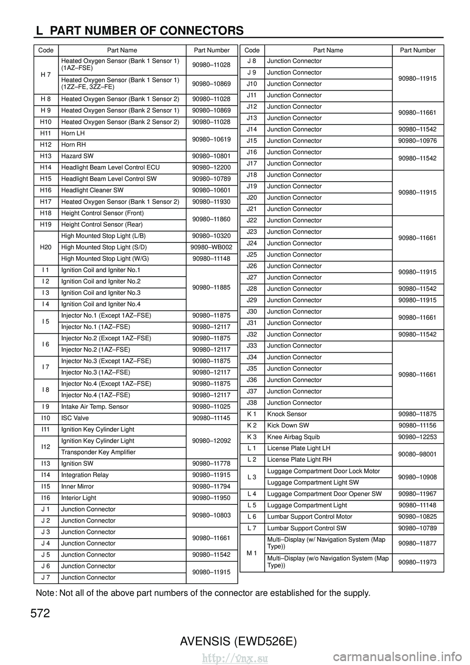
L PART NUMBER OF CONNECTORS
CodePart Name Part NumberCodePart Name Part Number
AVENSIS (EWD526E)
Note : Not all of the above part numbers of the connector are established for t\
he supply.
572
Heated Oxygen Sensor (Bank 1 Sensor 1)
(1AZ–FSE)90980–11028
H 7Heated Oxygen Sensor (Bank 1 Sensor 1)
(1ZZ–FE, 3ZZ–FE)90980–10869
H 8Heated Oxygen Sensor (Bank 1 Sensor 2)90980–11028
H 9Heated Oxygen Sensor (Bank 2 Sensor 1)90980–10869
H10Heated Oxygen Sensor (Bank 2 Sensor 2)90980–11028
H11Horn LH
H12Horn RH90980–10619
H13Hazard SW90980–10801
H14Headlight Beam Level Control ECU90980–12200
H15Headlight Beam Level Control SW90980–10789
H16Headlight Cleaner SW90980–10601
H17Heated Oxygen Sensor (Bank 1 Sensor 2)90980–11930
H18Height Control Sensor (Front)
H19Height Control Sensor (Rear)90980–11860
High Mounted Stop Light (L/B)90980–10320
H20High Mounted Stop Light (S/D)90980–WB002
High Mounted Stop Light (W/G)90980–11148
I 1Ignition Coil and Igniter No.1
I 2Ignition Coil and Igniter No.2
I 3Ignition Coil and Igniter No.390980–11885
I 4Ignition Coil and Igniter No.4
Injector No.1 (Except 1AZ–FSE)90980–11875I 5Injector No.1 (1AZ–FSE)90980–12117
Injector No.2 (Except 1AZ–FSE)90980–11875I 6Injector No.2 (1AZ–FSE)90980–12117
Injector No.3 (Except 1AZ–FSE)90980–11875I 7Injector No.3 (1AZ–FSE)90980–12117
Injector No.4 (Except 1AZ–FSE)90980–11875I 8Injector No.4 (1AZ–FSE)90980–12117
I 9Intake Air Temp. Sensor90980–11025
I10ISC Valve90980–11145
I11Ignition Key Cylinder Light
Ignition Key Cylinder Light90980–12092I12Transponder Key Amplifier
I13Ignition SW90980–11778
I14Integration Relay90980–11915
I15Inner Mirror90980–11794
I16Interior Light90980–11950
J 1Junction Connector
J 2Junction Connector90980–10803
J 3Junction Connector
J 4Junction Connector90980–11661
J 5Junction Connector90980–11542
J 6Junction Connector
J 7Junction Connector90980–11915
J 8Junction Connector
J 9Junction Connector
J10Junction Connector90980–11915
J11Junction Connector
J12Junction Connector
J13Junction Connector90980–11661
J14Junction Connector90980–11542
J15Junction Connector90980–10976
J16Junction Connector
J17Junction Connector90980–11542
J18Junction Connector
J19Junction Connector
J20Junction Connector90980–11915
J21Junction Connector
J22Junction Connector
J23Junction Connector
J24Junction Connector90980–11661
J25Junction Connector
J26Junction Connector
J27Junction Connector90980–11915
J28Junction Connector90980–11542
J29Junction Connector90980–11915
J30Junction Connector
J31Junction Connector90980–11661
J32Junction Connector90980–11542
J33Junction Connector
J34Junction Connector
J35Junction Connector
J36Junction Connector90980–11661
J37Junction Connector
J38Junction Connector
K 1Knock Sensor90980–11875
K 2Kick Down SW90980–11156
K 3Knee Airbag Squib90980–12253
L 1License Plate Light LH
L 2License Plate Light RH90080–98001
Luggage Compartment Door Lock MotorL 3Luggage Compartment Light SW90980–10908
L 4Luggage Compartment Door Opener SW90980–11967
L 5Luggage Compartment Light90980–11148
L 6Lumbar Support Control Motor90980–10825
L 7Lumbar Support Control SW90980–10789
Multi–Display (w/ Navigation System (Map
Type))90980–11877
M 1Multi–Display (w/o Navigation System (Map
Type))90980–11973
http://vnx.su
Page 2221 of 2234
AVENSIS (EWD526E)
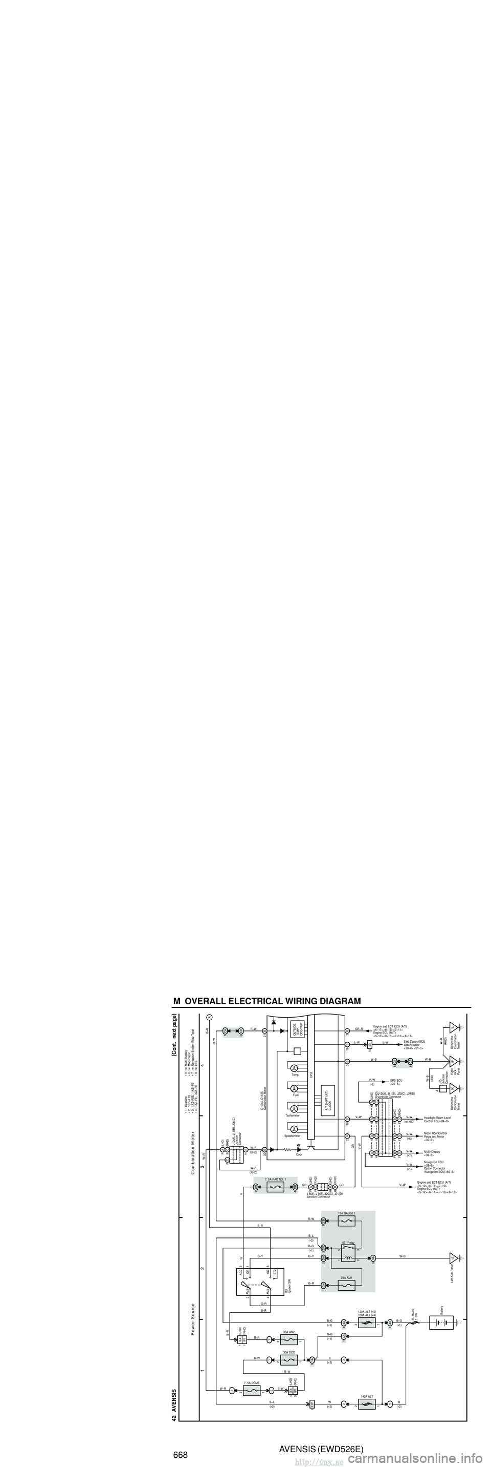
668 M OVERALL ELECTRICAL WIRING DIAGRAM
1 23
4
42 AVENSIS (
C ont. ne xt pa ge )
6
16 IE1A
Power Source
C ombination M eter
L–W
W–R L–W
GR–R
Engine and ECT ECU
(
A/T )
<5–17><6–13><7–11>
∗ 3 : 1AZ–FSE, 1AZ–FE
∗
2 : 1CD–FTV
∗
1 : Gasoline
SpeedometerTachometer Fuel
Temp.
Door
OUTSIDE
TEMP.
ODO/TRIP
20 B ∗
6 : w/ Moon Roof
5B
W–B
3B
19 B
Skid Control ECU
with Actuator
< 20–6> < 21–5>
Engine ECU
(
M/T )
<5–17><6–13><7–11><8–13>
C10 (
A )
, C11 (
B )
6
7. 5A DOME2 6
1
W–R B–R
∗
7 : w/ Navigation System (
Map Type )
Combination Meter
7. 5A RAD NO. 1
DH
3
DB
4
G
G
2
FC
HB
GR GR
B
W B–G
FL MAIN
3. 0W
Battery
120A ALT (
∗ 3 )
100A ALT (
∗ 4 )
B–W
3 ACC
IG1
AM1 1
I13Ignition SW
1DH
25A AM1
DN
1
DH
5
2 1 3
5
DA
9
10A GAUGE1
IG1 Relay
DB
7
IJ
Left Kick PanelB–G
G–R B–G
G–Y
R–W
W–B
3
(∗ 2 )
B–L
( ∗ 1 )
140A ALTB
( ∗ 2 )
2
1
3 4D
4B
1 2
3
G–R
(∗ 1 )
( ∗ 2 )
B–L
ED1 1
B–W
1
2
11A
30A DCC (∗ 2 )
( ∗ 2 )
1 1
5IP1
IE4
4 (
LHD )
( RHD )
B–W
4I
G2
ST2 6
AM2 CA
7
CD
6
R–W
21 B
R–W
IP
Right
Kick
Panel CK
6
CA
6
W–B
18 B B–R
G–Y
HC
HC
FB F HC
BF HC
B
V–W Headlight Beam Level
Control ECU< 24–3>
V–W Moon Roof Control
Relay and Motor
< 32–3>
V–W Multi–Display
< 39–6>
( ∗ 7 )
(
∗ 6 )
(
w/ HID )
V–W
V–WNavigation ECU
< 39–6>
( ∗ 5 )
Engine and ECT ECU (
A/T )
<5–12><6–11><7–10>
V–W
V–W
EPS ECU
< 23–4>
( ∗ 8 )
Engine ECU (
M/T )
<5–12><6–11><7–10><8–12>
1
( ∗ 1 )
14A
(
∗ 1 )
B–G
2
1
B–R
1
30A AM2
1IP1 IE4
1
(RHD )
(
LHD )
B–R
B–R
Option Connector
(
Navigation ECU )
< 50–3>
A/T SHIFT (
A/T )
CLOCK CPU∗
5 : w/ Multi–Display
∗ 4 : 1ZZ–FE, 3ZZ–FE ∗ 8 : w/ EPS
2A
GR
FC
FC
HBFA
(
LHD )
Junction
Connector
J10 (
A )
, J11 (
B )
, J26 (
C )
(
RHD )
(
LHD )
W–R
W–R
( RHD )
FA (
LHD )
HD (
RHD )
(
LHD )
(
RHD )Junction ConnectorJ 8(
A )
, J 9 (
B )
, J20 (
C )
, J21 (
D )
V–W
FD(
RHD )
FD
FD
HA HA HA HA
(
LHD )
Junction ConnectorJ10(
A )
, J11 (
B )
, J20 (
C )
, J21 (
D )(
RHD )
( LHD )
IL
Behind the
Combination
Meter
IK
Behind the
Combination
Meter A
Junction
Connector
J15W–B
W–B
( LHD )
(RHD )
AVENSIS (EWD526E)
669M
5
67
8
42 AVENSIS (
C ont' d )
(
C ont. ne xt pa ge )
C ombination M eter
Near the Starter
Buzzer
EI BR
4IK1
A
Y–G
16
2 1Y–G BR
E 7
BR
Engine Oil
Level Sensor
Fuel
Turn Signal and
Hazard Warning
Light System
< 15–2> < 15–3>
W–B
Illumination
System< 19–4> Tail
Turn LH
Turn RH
A
B–R
17 A1B 13B
14 B
Oil Level
2
Y–R BR
Y–R
1
1A
15 IK2F14Fuel Filter Warning SW
AVC–LAN
I/F 4A
A3
G–Y G
Multi–Display
< 39–6> < 40–3> (
∗ 2 )(
∗2 )(
∗2 )
(
∗ 2 )(
∗2 )
3 2
G–W
BR–W
5A 10ABR–W G–W
F25
15 IC1 6 IC1
15 IE1
1
2
W
W–R
IE1
4
11 A 12 A
W–R
W
A 1A/C Ambient
Temp. Sensor
IO
Instrument Panel
Reinforcement RH
(
∗ 2 )
(
∗ 2 )(
∗2 )
A/T OIL TEMP
Charge
ECT SNOW Seat Belt Glow
CRUISE
13 A A14
BEAN
I/F
Multiplex
Communication
System< 1–15>
<2–10><2–11>
A
15
(
∗ 9 )
Illumination A
B–R
CPU
C10 (
A )
, C11 (
B )Combination Meter ∗
5 : w/ Multi–Display
(
∗ 5 )
( ∗ 5 )
Taillight System
< 14–2>
∗
2 : 1CD–FTV
Behind the
Combination Meter
IK
W–B
AJ15Junction
Connector
(
RHD )
( LHD )
∗
9 : w/ Theft Deterrent
∗
1 : Gasoline
(
∗ 2 )(
∗2 )
( ∗ 2 )
W–B
( LHD ∗1 )
W–B
( RHD )
A A
A
A
J16Junction
ConnectorJ17Junction
Connector
Behind the
Combination Meter IL
W–B
( LHD ∗2 )
Fuel Sender
AVENSIS (EWD526E)
670 M OVERALL ELECTRICAL WIRING DIAGRAM
9 10 11
12
42 AVENSIS (
C ont' d )
10A
IGN
C ombination M eter
B–R
B–W
SRS
Brake ABS
Check Engine
EC
Engine Compartment Left 2 C
19 IK2
R–W
R–W
W–B
Y–B
R–W
Y–B
R–W
R–W
B–W
SRS System
< 22–4>
Engine Control System
<5–5><6–7>
<7–5><8–4>
(∗ 2 )(
∗ 1 )
C
11
VSC System< 20–10>
Oil Pressure
∗
2 : 1CD–FTV
∗
1 : Gasoline
1
9A 4B
9B 2B
19 IE1 (∗ 2 ) 11 B
TRC OFF
Slip
VSC
17 B
15 B
16 B
VSC System
< 20–10>
Rear Fog
ABS System< 21–3>
8A
8B
Rear Fog
Light System
< 16–2>
22 B
(
∗ 2 )
C10 (
A )
, C11 (
B )
Front Fog
7A
Front Fog
Light System
< 16–2>
O 2
CB 3
J 2
V 2
J 8 (
A )
, J26 (
B )
Brake Fluid Level
Warning SW
Combination Meter
Junction
Connector
Junction
Connector Oil Pressure SW
Vacuum
SW
DH
2DA 18
AC BA
P/S
6B
EPS System< 23–2>
Filter
Beam Level
Headlight Beam Level Control
System< 24–3>
10 B
A
Multiplex Communication
System< 1–14>
High Beam
6
12 B
Headlight System
<13–4>
(w/ VSC )
(
w/ VSC )
(
w/ VSC )
A
CA
AB (
LHD )
( RHD )
( LHD )
( RHD )Multiplex Communication
System< 1–14>
Headlight System
< 13–4>
( w/ HID )
http://vnx.su
Page 2222 of 2234

AVENSIS (EWD526E)
668 M OVERALL ELECTRICAL WIRING DIAGRAM
1 23
4
42 AVENSIS (
C ont. ne xt pa ge )
6
16 IE1A
Power Source
C ombination M eter
L–W
W–R L–W
GR–R
Engine and ECT ECU
(
A/T )
<5–17><6–13><7–11>
∗ 3 : 1AZ–FSE, 1AZ–FE
∗
2 : 1CD–FTV
∗
1 : Gasoline
SpeedometerTachometer Fuel
Temp.
Door
OUTSIDE
TEMP.
ODO/TRIP
20 B ∗
6 : w/ Moon Roof
5B
W–B
3B
19 B
Skid Control ECU
with Actuator
< 20–6> < 21–5>
Engine ECU
(
M/T )
<5–17><6–13><7–11><8–13>
C10 (
A )
, C11 (
B )
6
7. 5A DOME2 6
1
W–R B–R
∗
7 : w/ Navigation System (
Map Type )
Combination Meter
7. 5A RAD NO. 1
DH
3
DB
4
G
G
2
FC
HB
GR GR
B
W B–G
FL MAIN
3. 0W
Battery
120A ALT (
∗ 3 )
100A ALT (
∗ 4 )
B–W
3 ACC
IG1
AM1 1
I13Ignition SW
1DH
25A AM1
DN
1
DH
5
2 1 3
5
DA
9
10A GAUGE1
IG1 Relay
DB
7
IJ
Left Kick PanelB–G
G–R B–G
G–Y
R–W
W–B
3
(∗ 2 )
B–L
( ∗ 1 )
140A ALTB
( ∗ 2 )
2
1
3 4D
4B
1 2
3
G–R
(∗ 1 )
( ∗ 2 )
B–L
ED1 1
B–W
1
2
11A
30A DCC (∗ 2 )
( ∗ 2 )
1 1
5IP1
IE4
4 (
LHD )
( RHD )
B–W
4I
G2
ST2 6
AM2 CA
7
CD
6
R–W
21 B
R–W
IP
Right
Kick
Panel CK
6
CA
6
W–B
18 B B–R
G–Y
HC
HC
FB F HC
BF HC
B
V–W Headlight Beam Level
Control ECU< 24–3>
V–W Moon Roof Control
Relay and Motor
< 32–3>
V–W Multi–Display
< 39–6>
( ∗ 7 )
(
∗ 6 )
(
w/ HID )
V–W
V–WNavigation ECU
< 39–6>
( ∗ 5 )
Engine and ECT ECU (
A/T )
<5–12><6–11><7–10>
V–W
V–W
EPS ECU
< 23–4>
( ∗ 8 )
Engine ECU (
M/T )
<5–12><6–11><7–10><8–12>
1
( ∗ 1 )
14A
(
∗ 1 )
B–G
2
1
B–R
1
30A AM2
1IP1 IE4
1
(RHD )
(
LHD )
B–R
B–R
Option Connector
(
Navigation ECU )
< 50–3>
A/T SHIFT (
A/T )
CLOCK CPU∗
5 : w/ Multi–Display
∗ 4 : 1ZZ–FE, 3ZZ–FE ∗ 8 : w/ EPS
2A
GR
FC
FC
HBFA
(
LHD )
Junction
Connector
J10 (
A )
, J11 (
B )
, J26 (
C )
(
RHD )
(
LHD )
W–R
W–R
( RHD )
FA (
LHD )
HD (
RHD )
(
LHD )
(
RHD )Junction ConnectorJ 8(
A )
, J 9 (
B )
, J20 (
C )
, J21 (
D )
V–W
FD(
RHD )
FD
FD
HA HA HA HA
(
LHD )
Junction ConnectorJ10(
A )
, J11 (
B )
, J20 (
C )
, J21 (
D )(
RHD )
( LHD )
IL
Behind the
Combination
Meter
IK
Behind the
Combination
Meter A
Junction
Connector
J15W–B
W–B
( LHD )
(RHD )
AVENSIS (EWD526E)
669M
5
67
8
42 AVENSIS (
C ont' d )
(
C ont. ne xt pa ge )
C ombination M eter
Near the Starter
Buzzer
EI BR
4IK1
A
Y–G
16
2 1Y–G BR
E 7
BR
Engine Oil
Level Sensor
Fuel
Turn Signal and
Hazard Warning
Light System
< 15–2> < 15–3>
W–B
Illumination
System< 19–4> Tail
Turn LH
Turn RH
A
B–R
17 A1B 13B
14 B
Oil Level
2
Y–R BR
Y–R
1
1A
15 IK2F14Fuel Filter Warning SW
AVC–LAN
I/F 4A
A3
G–Y G
Multi–Display
< 39–6> < 40–3> (
∗ 2 )(
∗2 )(
∗2 )
(
∗ 2 )(
∗2 )
3 2
G–W
BR–W
5A 10ABR–W G–W
F25
15 IC1 6 IC1
15 IE1
1
2
W
W–R
IE1
4
11 A 12 A
W–R
W
A 1A/C Ambient
Temp. Sensor
IO
Instrument Panel
Reinforcement RH
(
∗ 2 )
(
∗ 2 )(
∗2 )
A/T OIL TEMP
Charge
ECT SNOW Seat Belt Glow
CRUISE
13 A A14
BEAN
I/F
Multiplex
Communication
System< 1–15>
<2–10><2–11>
A
15
(
∗ 9 )
Illumination A
B–R
CPU
C10 (
A )
, C11 (
B )Combination Meter ∗
5 : w/ Multi–Display
(
∗ 5 )
( ∗ 5 )
Taillight System
< 14–2>
∗
2 : 1CD–FTV
Behind the
Combination Meter
IK
W–B
AJ15Junction
Connector
(
RHD )
( LHD )
∗
9 : w/ Theft Deterrent
∗
1 : Gasoline
(
∗ 2 )(
∗2 )
( ∗ 2 )
W–B
( LHD ∗1 )
W–B
( RHD )
A A
A
A
J16Junction
ConnectorJ17Junction
Connector
Behind the
Combination Meter IL
W–B
( LHD ∗2 )
Fuel Sender
AVENSIS (EWD526E)
670 M OVERALL ELECTRICAL WIRING DIAGRAM
9 10 11
12
42 AVENSIS (
C ont' d )
10A
IGN
C ombination M eter
B–R
B–W
SRS
Brake ABS
Check Engine
EC
Engine Compartment Left 2 C
19 IK2
R–W
R–W
W–B
Y–B
R–W
Y–B
R–W
R–W
B–W
SRS System
< 22–4>
Engine Control System
<5–5><6–7>
<7–5><8–4>
(∗ 2 )(
∗ 1 )
C
11
VSC System< 20–10>
Oil Pressure
∗
2 : 1CD–FTV
∗
1 : Gasoline
1
9A 4B
9B 2B
19 IE1 (∗ 2 ) 11 B
TRC OFF
Slip
VSC
17 B
15 B
16 B
VSC System
< 20–10>
Rear Fog
ABS System< 21–3>
8A
8B
Rear Fog
Light System
< 16–2>
22 B
(
∗ 2 )
C10 (
A )
, C11 (
B )
Front Fog
7A
Front Fog
Light System
< 16–2>
O 2
CB 3
J 2
V 2
J 8 (
A )
, J26 (
B )
Brake Fluid Level
Warning SW
Combination Meter
Junction
Connector
Junction
Connector Oil Pressure SW
Vacuum
SW
DH
2DA 18
AC BA
P/S
6B
EPS System< 23–2>
Filter
Beam Level
Headlight Beam Level Control
System< 24–3>
10 B
A
Multiplex Communication
System< 1–14>
High Beam
6
12 B
Headlight System
<13–4>
(w/ VSC )
(
w/ VSC )
(
w/ VSC )
A
CA
AB (
LHD )
( RHD )
( LHD )
( RHD )Multiplex Communication
System< 1–14>
Headlight System
< 13–4>
( w/ HID )
http://vnx.su
Page 2223 of 2234
AVENSIS (EWD526E)
668 M OVERALL ELECTRICAL WIRING DIAGRAM
1 23
4
42 AVENSIS (
C ont. ne xt pa ge )
6
16 IE1A
Power Source
C ombination M eter
L–W
W–R L–W
GR–R
Engine and ECT ECU
(
A/T )
<5–17><6–13><7–11>
∗ 3 : 1AZ–FSE, 1AZ–FE
∗
2 : 1CD–FTV
∗
1 : Gasoline
SpeedometerTachometer Fuel
Temp.
Door
OUTSIDE
TEMP.
ODO/TRIP
20 B ∗
6 : w/ Moon Roof
5B
W–B
3B
19 B
Skid Control ECU
with Actuator
< 20–6> < 21–5>
Engine ECU
(
M/T )
<5–17><6–13><7–11><8–13>
C10 (
A )
, C11 (
B )
6
7. 5A DOME2 6
1
W–R B–R
∗
7 : w/ Navigation System (
Map Type )
Combination Meter
7. 5A RAD NO. 1
DH
3
DB
4
G
G
2
FC
HB
GR GR
B
W B–G
FL MAIN
3. 0W
Battery
120A ALT (
∗ 3 )
100A ALT (
∗ 4 )
B–W
3 ACC
IG1
AM1 1
I13Ignition SW
1DH
25A AM1
DN
1
DH
5
2 1 3
5
DA
9
10A GAUGE1
IG1 Relay
DB
7
IJ
Left Kick PanelB–G
G–R B–G
G–Y
R–W
W–B
3
(∗ 2 )
B–L
( ∗ 1 )
140A ALTB
( ∗ 2 )
2
1
3 4D
4B
1 2
3
G–R
(∗ 1 )
( ∗ 2 )
B–L
ED1 1
B–W
1
2
11A
30A DCC (∗ 2 )
( ∗ 2 )
1 1
5IP1
IE4
4 (
LHD )
( RHD )
B–W
4I
G2
ST2 6
AM2 CA
7
CD
6
R–W
21 B
R–W
IP
Right
Kick
Panel CK
6
CA
6
W–B
18 B B–R
G–Y
HC
HC
FB F HC
BF HC
B
V–W Headlight Beam Level
Control ECU< 24–3>
V–W Moon Roof Control
Relay and Motor
< 32–3>
V–W Multi–Display
< 39–6>
( ∗ 7 )
(
∗ 6 )
(
w/ HID )
V–W
V–WNavigation ECU
< 39–6>
( ∗ 5 )
Engine and ECT ECU (
A/T )
<5–12><6–11><7–10>
V–W
V–W
EPS ECU
< 23–4>
( ∗ 8 )
Engine ECU (
M/T )
<5–12><6–11><7–10><8–12>
1
( ∗ 1 )
14A
(
∗ 1 )
B–G
2
1
B–R
1
30A AM2
1IP1 IE4
1
(RHD )
(
LHD )
B–R
B–R
Option Connector
(
Navigation ECU )
< 50–3>
A/T SHIFT (
A/T )
CLOCK CPU∗
5 : w/ Multi–Display
∗ 4 : 1ZZ–FE, 3ZZ–FE ∗ 8 : w/ EPS
2A
GR
FC
FC
HBFA
(
LHD )
Junction
Connector
J10 (
A )
, J11 (
B )
, J26 (
C )
(
RHD )
(
LHD )
W–R
W–R
( RHD )
FA (
LHD )
HD (
RHD )
(
LHD )
(
RHD )Junction ConnectorJ 8(
A )
, J 9 (
B )
, J20 (
C )
, J21 (
D )
V–W
FD(
RHD )
FD
FD
HA HA HA HA
(
LHD )
Junction ConnectorJ10(
A )
, J11 (
B )
, J20 (
C )
, J21 (
D )(
RHD )
( LHD )
IL
Behind the
Combination
Meter
IK
Behind the
Combination
Meter A
Junction
Connector
J15W–B
W–B
( LHD )
(RHD )
AVENSIS (EWD526E)
669M
5
67
8
42 AVENSIS (
C ont' d )
(
C ont. ne xt pa ge )
C ombination M eter
Near the Starter
Buzzer
EI BR
4IK1
A
Y–G
16
2 1Y–G BR
E 7
BR
Engine Oil
Level Sensor
Fuel
Turn Signal and
Hazard Warning
Light System
< 15–2> < 15–3>
W–B
Illumination
System< 19–4> Tail
Turn LH
Turn RH
A
B–R
17 A1B 13B
14 B
Oil Level
2
Y–R BR
Y–R
1
1A
15 IK2F14Fuel Filter Warning SW
AVC–LAN
I/F 4A
A3
G–Y G
Multi–Display
< 39–6> < 40–3> (
∗ 2 )(
∗2 )(
∗2 )
(
∗ 2 )(
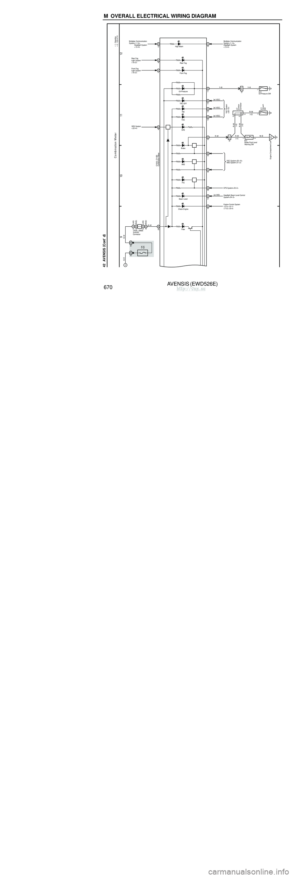
∗2 )
3 2
G–W
BR–W
5A 10ABR–W G–W
F25
15 IC1 6 IC1
15 IE1
1
2
W
W–R
IE1
4
11 A 12 A
W–R
W
A 1A/C Ambient
Temp. Sensor
IO
Instrument Panel
Reinforcement RH
(
∗ 2 )
(
∗ 2 )(
∗2 )
A/T OIL TEMP
Charge
ECT SNOW Seat Belt Glow
CRUISE
13 A A14
BEAN
I/F
Multiplex
Communication
System< 1–15>
<2–10><2–11>
A
15
(
∗ 9 )
Illumination A
B–R
CPU
C10 (
A )
, C11 (
B )Combination Meter ∗
5 : w/ Multi–Display
(
∗ 5 )
( ∗ 5 )
Taillight System
< 14–2>
∗
2 : 1CD–FTV
Behind the
Combination Meter
IK
W–B
AJ15Junction
Connector
(
RHD )
( LHD )
∗
9 : w/ Theft Deterrent
∗
1 : Gasoline
(
∗ 2 )(
∗2 )
( ∗ 2 )
W–B
( LHD ∗1 )
W–B
( RHD )
A A
A
A
J16Junction
ConnectorJ17Junction
Connector
Behind the
Combination Meter IL
W–B
( LHD ∗2 )
Fuel Sender
AVENSIS (EWD526E)
670 M OVERALL ELECTRICAL WIRING DIAGRAM
9 10 11
12
42 AVENSIS (
C ont' d )
10A
IGN
C ombination M eter
B–R
B–W
SRS
Brake ABS
Check Engine
EC
Engine Compartment Left 2 C
19 IK2
R–W
R–W
W–B
Y–B
R–W
Y–B
R–W
R–W
B–W
SRS System
< 22–4>
Engine Control System
<5–5><6–7>
<7–5><8–4>
(∗ 2 )(
∗ 1 )
C
11
VSC System< 20–10>
Oil Pressure
∗
2 : 1CD–FTV
∗
1 : Gasoline
1
9A 4B
9B 2B
19 IE1 (∗ 2 ) 11 B
TRC OFF
Slip
VSC
17 B
15 B
16 B
VSC System
< 20–10>
Rear Fog
ABS System< 21–3>
8A
8B
Rear Fog
Light System
< 16–2>
22 B
(
∗ 2 )
C10 (
A )
, C11 (
B )
Front Fog
7A
Front Fog
Light System
< 16–2>
O 2
CB 3
J 2
V 2
J 8 (
A )
, J26 (
B )
Brake Fluid Level
Warning SW
Combination Meter
Junction
Connector
Junction
Connector Oil Pressure SW
Vacuum
SW
DH
2DA 18
AC BA
P/S
6B
EPS System< 23–2>
Filter
Beam Level
Headlight Beam Level Control
System< 24–3>
10 B
A
Multiplex Communication
System< 1–14>
High Beam
6
12 B
Headlight System
<13–4>
(w/ VSC )
(
w/ VSC )
(
w/ VSC )
A
CA
AB (
LHD )
( RHD )
( LHD )
( RHD )Multiplex Communication
System< 1–14>
Headlight System
< 13–4>
( w/ HID )
http://vnx.su