Page 435 of 2234

13±3
AVENSIS REPAIR MANUAL (RM1018E)
TURBO CHARGER SYSTEM (1CD±FTV)
PRECAUTION
1. MAINTENANCE PRECAUTION
(a) Do not stop th")
1302Y±03
A77119
A77120
A77121
±
INTAKE TURBO CHARGER SYSTEM (1CD±FTV)
13±3
AVENSIS REPAIR MANUAL (RM1018E)
TURBO CHARGER SYSTEM (1CD±FTV)
PRECAUTION
1. MAINTENANCE PRECAUTION
(a) Do not stop the engine immediately after pulling a trailer,
or after driving at a high speed, or uphill drive. Let the en-
gine Idle for 20 to 120 seconds before turn the ignition
switch OFF (According as the driving condition, the idling
time varies).
(b) Avoid quick acceleration or quickly accelerating the en- gine RPM immediately after the starting a cold engine.
(c) If the turbocharger is found to be defective, it must be re-
placed. Also, inspect a source of the trouble including
conditions of the turbocharger that having been used. Re-
pair or replace the followings as necessary:
(1) Engine oil (Level and quality)
(2) Oil lines leading to the turbocharger
(d) Pay due attention when removing and reinstalling the turbocharger assembly. Do not drop, or do not give shock,
or do not grasp easily±deformed assembly parts such as
the actuator or push rod in removal and reinstallation.
(e) Before removal, cover both the intake and exhaust ports
and the oil inlet to prevent dirt or foreign objects from be-
ing introduced.
(f) If replacing the turbocharger, check for deposits in the oil pipe. If necessary, replace the oil pipe too.
(g) Thoroughly remove old gasket sticking to the lubrication oil pipe flange and the turbocharger oil flange.
(h) If replacing the bolt(s) or nut(s), must use Toyota genuine parts to prevent breakage or deformation.
(i) If replacing the turbocharger, put 20 cm
3 (1.2 cu in.) of
fresh oil into the turbocharger oil inlet hole and turn the tur-
bine wheel by hand to spread oil to the bearing.
(j) If overhauling or replacing the engine, cut the fuel supply after reassembly and crank the engine for 30 seconds to
feed oil throughout the engine then run the engine at idle
for 60 seconds.
http://vnx.su
Page 446 of 2234
A64328
2 to 7 mm0 to 2 mm
A78274
Upward90�
Clamp
Bolt
±
INTAKETURBOCHARGER SUB±ASSY(1CD±FTV)
13±17
AVENSIS REPAIR MANUAL (RM1018E)
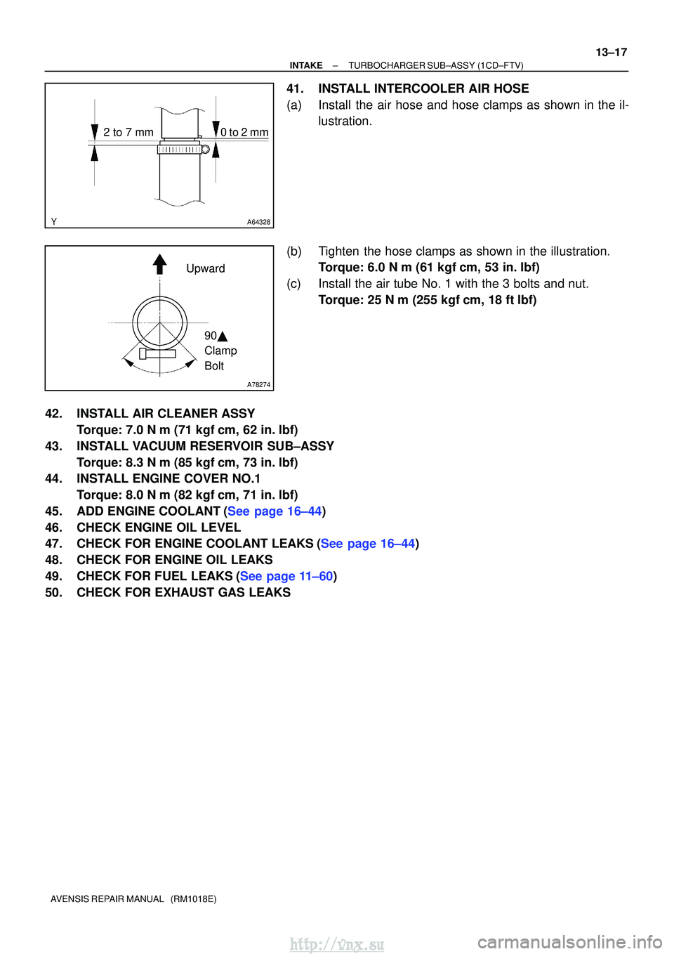
41.INSTALL INTERCOOLER AIR HOSE
(a)Install the air hose and hose clamps as shown in the il-
lustration.
(b)Tighten the hose clamps as shown in the illustration. Torque: 6.0 N �m (61 kgf�cm, 53 in. �lbf)
(c)Install the air tube No. 1 with the 3 bolts and nut. Torque: 25 N �m (255 kgf�cm, 18 ft�lbf)
42.INSTALL AIR CLEANER ASSY Torque: 7.0 N �m (71 kgf�cm, 62 in. �lbf)
43.INSTALL VACUUM RESERVOIR SUB±ASSY Torque: 8.3 N �m (85 kgf�cm, 73 in. �lbf)
44.INSTALL ENGINE COVER NO.1
Torque: 8.0 N �m (82 kgf�cm, 71 in. �lbf)
45.ADD ENGINE COOLANT(See page 16±44)
46. CHECK ENGINE OIL LEVEL
47.CHECK FOR ENGINE COOLANT LEAKS(See page 16±44)
48. CHECK FOR ENGINE OIL LEAKS
49.CHECK FOR FUEL LEAKS(See page 11±60)
50. CHECK FOR EXHAUST GAS LEAKS
http://vnx.su
Page 473 of 2234

14±321
AVENSIS REPAIR MANUAL (RM1018E)
40. SET NO. 1 CYLINDER TO TDC/COMPRESSION
(a) Using")
90�
A09683
TDC Mark
Dot Mark
A09624
A09625
A09626
Alignment Mark
±
ENGINE MECHANICAL CAMSHAFT (1CD±FTV)
14±321
AVENSIS REPAIR MANUAL (RM1018E)
40. SET NO. 1 CYLINDER TO TDC/COMPRESSION
(a) Using the crankshaft pulley bolt, turn the crankshaft to set
the dot mark of the crankshaft timing pulley at the position
of 90� BTDC.
NOTICE:
If the timing belt is disengaged, having the crankshaft tim-
ing pulley at wrong angle can cause the piston head and
valve head to come into contact with each other.
41. INSTALL CAMSHAFT
NOTICE:
Since the thrust clearance of the camshaft is small, the
camshaft must be kept level while it is being installed. If the
camshaft is not kept level, damage to the cylinder head or
the camshaft may result. To avoid this, the following proce-
dures should be carried out.
(a) Place the camshaft carrier on the cylinder head.
(b) Install the camshaft sub±assy No. 1.
(c) Apply engine oil to the cam and gear of the camshaft, and the journal of the camshaft carrier.
(d) Place the intake camshaft on the camshaft carrier as
shown in the illustration so that the No. 3 and No. 4 of cyl-
inder cam lobes face downward.
42. INSTALL NO.2 CAMSHAFT
(a) Install the camshaft sub±assy No. 2.
(b) Apply engine oil to the cam and gear of the camshaft, and the journal of the camshaft carrier.
(c) Engage the exhaust camshaft gear and the intake cam- shaft gear by aligning the alignment marks on each gear.
(d) Roll down the exhaust camshaft onto the bearing journals
while engaging gears with each other.
http://vnx.su
Page 543 of 2234
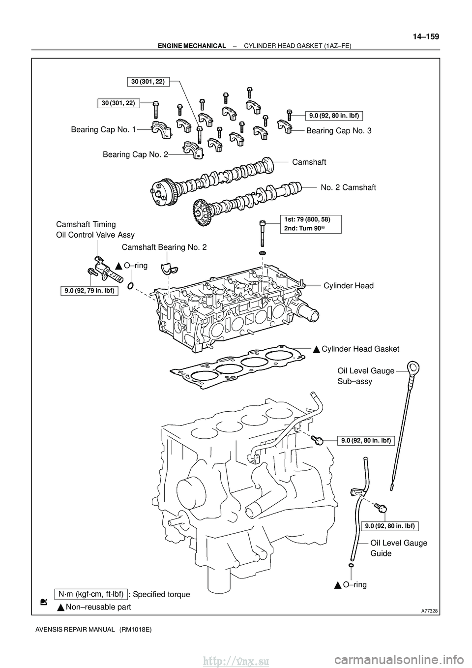
A77328
N´m (kgf´cm, ft´lbf): Specified torque
� Non±reusable part
30 (301, 22)
� O±ring
Bearing Cap No. 1
Bearing Cap No. 2
9.0 (92, 80 in. �lbf)
Bearing Cap No. 3
Camshaft
No. 2 Camshaft
Camshaft Bearing No. 2
Camshaft Timing
Oil Control Valve Assy
Cylinder Head
� Cylinder Head Gasket
9.0 (92, 80 in. �lbf)
Oil Level Gauge
Sub±assy
9.0 (92, 80 in. �lbf)
� O±ring
Oil Level Gauge
Guide
1st: 79 (800, 58)
2nd: Turn 90 �
30 (301, 22)
9.0 (92, 79 in. �lbf)
±
ENGINE MECHANICAL CYLINDER HEAD GASKET (1AZ±FE)
14±159
AVENSIS REPAIR MANUAL (RM1018E)
http://vnx.su
Page 581 of 2234
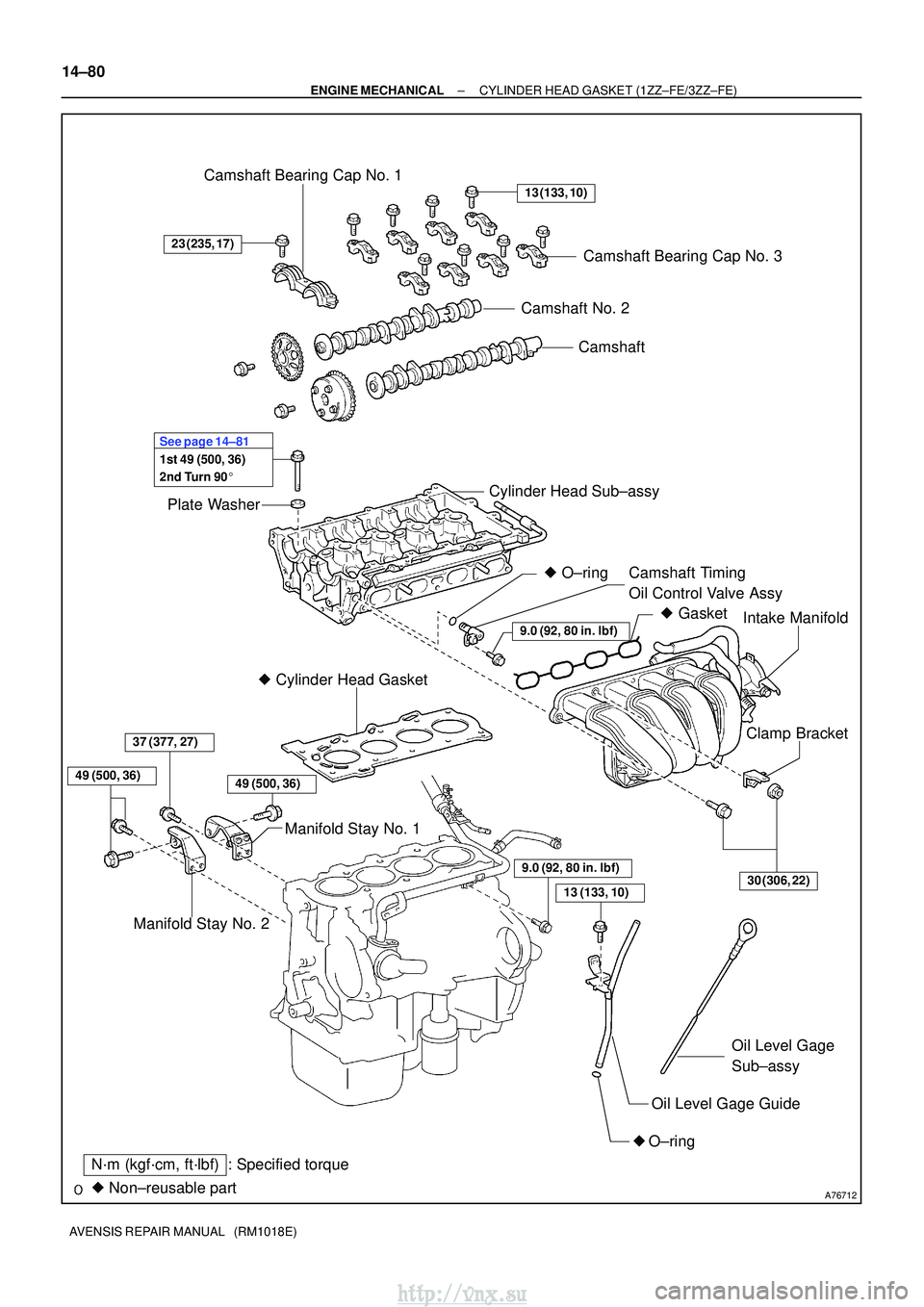
A76712
Camshaft
Camshaft No. 2
Plate Washer Camshaft Bearing Cap No. 1
Camshaft Bearing Cap No. 3
Cylinder Head Sub±assy Camshaft Timing
Oil Control Valve Assy
� Cylinder Head Gasket
Manifold Stay No. 1 Intake Manifold
Clamp Bracket
Oil Level Gage Guide
� O±ring Oil Level Gage
Sub±assy
� Non±reusable part
N´m (kgf´cm, ft´lbf): Specified torque
13 (133, 10)
23 (235, 17)
30 (306, 22)
9.0 (92, 80 in.�lbf)
1st 49 (500, 36)
2nd Turn 90� See page 14±81
49 (500, 36)
�
Gasket
Manifold Stay No. 2
37 (377, 27)
� O±ring
9.0 (92, 80 in.� lbf)
13 (133, 10)
49 (500, 36)
14±80
±
ENGINE MECHANICAL CYLINDER HEAD GASKET (1ZZ±FE/3ZZ±FE)
AVENSIS REPAIR MANUAL (RM1018E)
http://vnx.su
Page 584 of 2234

14±83
AVENSIS REPAIR MANUAL (RM1018E)
22. DISCONNECT VENTILATION HOSE
(a) Disconnect the ventilation hose fr")
A65078
A64058
A79363
A64026
±
ENGINE MECHANICAL CYLINDER HEAD GASKET (1ZZ±FE/3ZZ±FE)
14±83
AVENSIS REPAIR MANUAL (RM1018E)
22. DISCONNECT VENTILATION HOSE
(a) Disconnect the ventilation hose from the cylinder head
cover.
23. DISCONNECT VENTILATION HOSE NO.2
(a) Disconnect the ventilation hose from the cylinder head cover.
24. REMOVE INTAKE MANIFOLD
(a) Disconnect the 2 water hoses from the throttle body.
(b) Disconnect the ventilation hose and ventilation hose No. 2 from the cylinder head cover.
(c) Disconnect the vacuum hose from the water by±pass
pipe No. 1.
(d) Remove the 4 bolts, 2 nuts and 2 wire brackets.
(e) Remove the intake manifold and the throttle body assem- bly.
(f) Remove the gasket from the intake manifold and the throttle body assembly.
25. REMOVE OIL LEVEL GAGE SUB±ASSY
(a) Remove the oil level gage from the oil level gage guide.
26. REMOVE OIL LEVEL GAGE GUIDE
(a) Disconnect the crankshaft position sensor cramp.
(b) Remove the bolt and the oil level gage guide.
27. SEPARATE WATER BY±PASS PIPE NO.1
(a) Remove the 2 bolts which are used to secure the water by±pass pipe.
http://vnx.su
Page 595 of 2234

AVENSIS REPAIR MANUAL (RM1018E)
68.INSTALL MANIFOLD STAY
(a)Install the manifold stay with the")
A76720
AAB
A76721
B06777
A64026
A79363
14±94
±
ENGINE MECHANICALCYLINDER HEAD GASKET(1ZZ±FE/3ZZ±FE)
AVENSIS REPAIR MANUAL (RM1018E)
68.INSTALL MANIFOLD STAY
(a)Install the manifold stay with the 3 bolts. Torque:
37 N�m (377 kgf�cm, 27 ft�lbf) for Bolt A
49 N�m (500 kgf�cm, 36 ft�lbf) for Bolt B
69.INSTALL MANIFOLD STAY NO.2
(a)Install the manifold stay with the 3 bolts. Torque: 49 N �m (500 kgf�cm, 36 ft�lbf)
70.INSTALL EXHAUST PIPE ASSY FRONT (See page 15±2)
71. INSTALL CAMSHAFT TIMING OIL CONTROL VALVE ASSY
(a) Apply a light coat of engine oil on a new O±ring, and install it to the camshaft timing oil control valve.
(b) Install the camshaft timing oil control valve with the bolt.
Torque: 9.0 N �m (92 kgf �cm, 80 in. �lbf)
72. INSTALL WATER BY±PASS PIPE NO.1
(a) Install a new gasket and water by±pass pipe with the 2 nuts and 2 bolts.
Torque: 9.0 N �m (92 kgf �cm, 80 in. �lbf)
73. INSTALL OIL LEVEL GAGE GUIDE
(a) Apply a light coat of engine oil on a new O±ring, and install it to the oil level gage guide.
(b) Install the oil level gage guide with the bolt.
Torque: 13 N �m (133 kgf� cm, 10 ft�lbf)
74. INSTALL INTAKE MANIFOLD
(a) Install a new gasket to the intake manifold.
(b) Install the intake manifold and the throttle body assembly with the 2 brackets, 4 bolts and 2 nuts.
Torque: 30 N �m (306 kgf� cm, 22 ft�lbf)
(c) Connect the 2 vacuum hoses to the intake manifold.
(d) Connect the 2 water hoses to the throttle body.
http://vnx.su
Page 632 of 2234
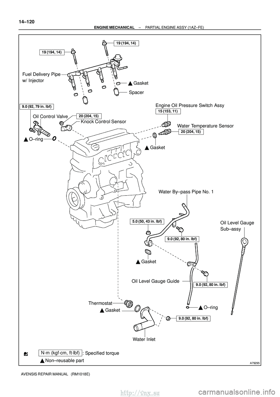
A79295
N´m (kgf´cm, ft´lbf): Specified torque
� Non±reusable part
5.0 (50, 43 in. �lbf)
� O±ring
� Gasket �
Gasket �
Gasket
�
Gasket
� O±ring
15 (153, 11)
20 (204, 15)
9.0 (92, 80 in. �lbf)
9.0 (92, 80 in. �lbf)
Fuel Delivery Pipe
w/ Injector
Oil Control Valve Knock Control Sensor Spacer
Water By±pass Pipe No. 1 Oil Level Gauge
Sub±assy
Oil Level Gauge Guide
Water Inlet
9.0 (92, 79 in. �lbf)Engine Oil Pressure Switch Assy
Water Temperature Sensor
Thermostat
9.0 (92, 80 in. �lbf)
19 (194, 14)
19 (194, 14)
20 (204, 15)
14±120
±
ENGINE MECHANICAL PARTIAL ENGINE ASSY (1AZ±FE)
AVENSIS REPAIR MANUAL (RM1018E)
http://vnx.su