Page 1102 of 2234
320VT±01
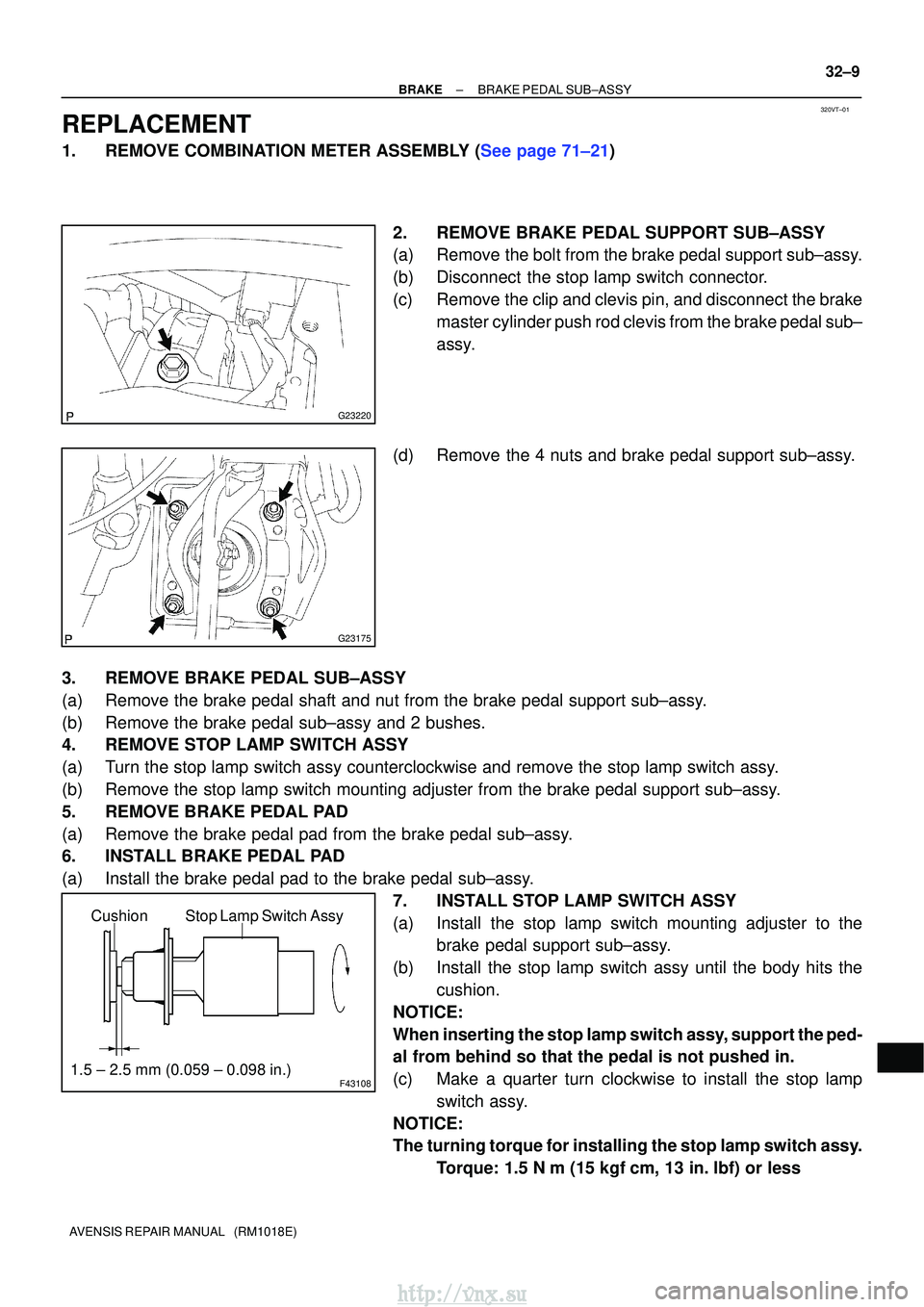
G23220
G23175
F43108
Stop Lamp Switch Assy
Cushion
1.5 ± 2.5 mm (0.059 ± 0.098 in.)
±
BRAKE BRAKE PEDAL SUB±ASSY
32±9
AVENSIS REPAIR MANUAL (RM1018E)
REPLACEMENT
1.REMOVE COMBINATION METER ASSEMBLY (See page 71±21)
2. REMOVE BRAKE PEDAL SUPPORT SUB±ASSY
(a) Remove the bolt from the brake pedal support sub±assy.
(b) Disconnect the stop lamp switch connector.
(c) Remove the clip and clevis pin, and disconnect the brakemaster cylinder push rod clevis from the brake pedal sub±
assy.
(d) Remove the 4 nuts and brake pedal support sub±assy.
3. REMOVE BRAKE PEDAL SUB±ASSY
(a) Remove the brake pedal shaft and nut from the brake pedal support sub±\
assy.
(b) Remove the brake pedal sub±assy and 2 bushes.
4. REMOVE STOP LAMP SWITCH ASSY
(a) Turn the stop lamp switch assy counterclockwise and remove the stop lamp \
switch assy.
(b) Remove the stop lamp switch mounting adjuster from the brake pedal suppo\
rt sub±assy.
5. REMOVE BRAKE PEDAL PAD
(a) Remove the brake pedal pad from the brake pedal sub±assy.
6. INSTALL BRAKE PEDAL PAD
(a) Install the brake pedal pad to the brake pedal sub±assy. 7. INSTALL STOP LAMP SWITCH ASSY
(a) Install the stop lamp switch mounting adjuster to thebrake pedal support sub±assy.
(b) Install the stop lamp switch assy until the body hits the cushion.
NOTICE:
When inserting the stop lamp switch assy, support the ped-
al from behind so that the pedal is not pushed in.
(c) Make a quarter turn clockwise to install the stop lamp switch assy.
NOTICE:
The turning torque for installing the stop lamp switch assy. Torque: 1.5 N� m (15 kgf�cm, 13 in. �lbf) or less
http://vnx.su
Page 1129 of 2234
320W2±01
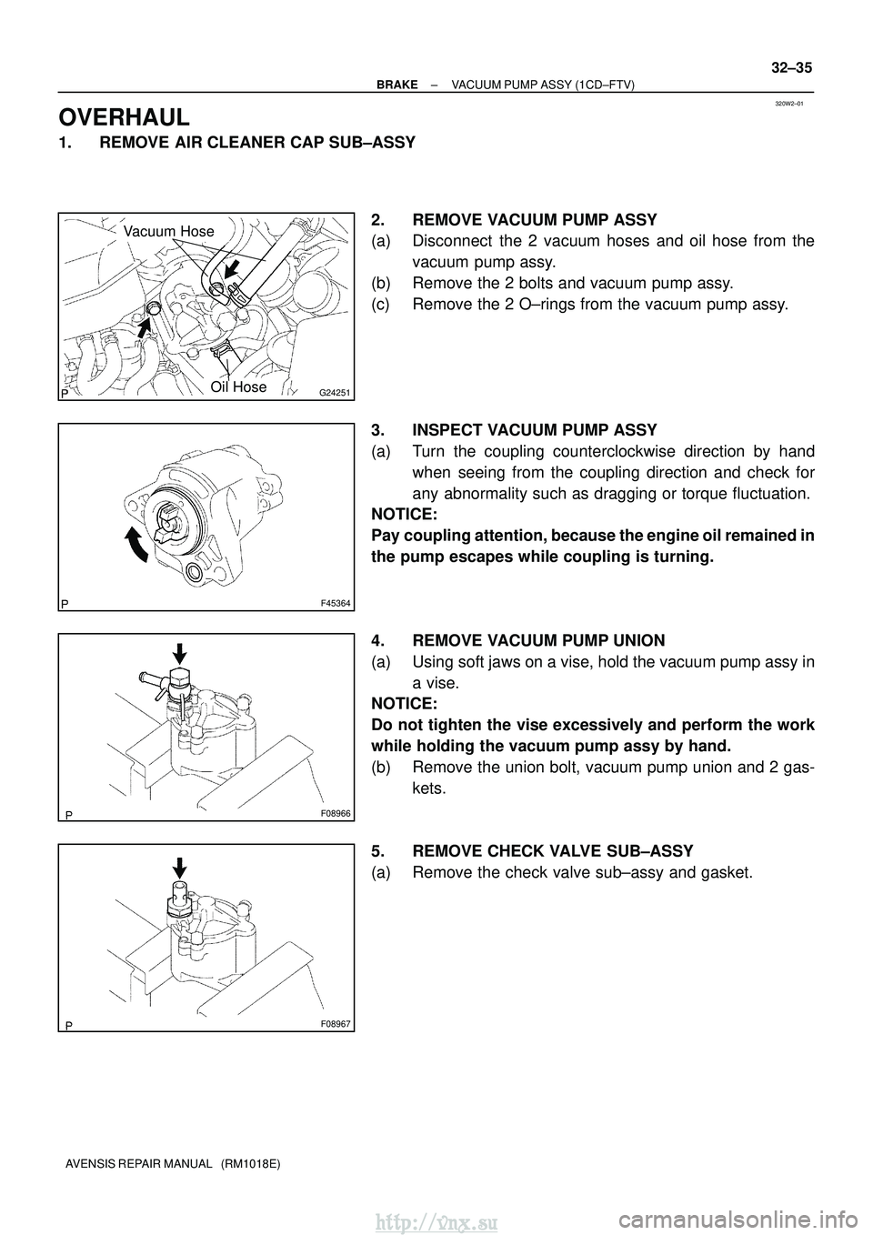
G24251
Vacuum Hose
Oil Hose
F45364
F08966
F08967
±
BRAKE VACUUM PUMP ASSY (1CD±FTV)
32±35
AVENSIS REPAIR MANUAL (RM1018E)
OVERHAUL
1. REMOVE AIR CLEANER CAP SUB±ASSY
2. REMOVE VACUUM PUMP ASSY
(a) Disconnect the 2 vacuum hoses and oil hose from thevacuum pump assy.
(b) Remove the 2 bolts and vacuum pump assy.
(c) Remove the 2 O±rings from the vacuum pump assy.
3. INSPECT VACUUM PUMP ASSY
(a) Turn the coupling counterclockwise direction by hand when seeing from the coupling direction and check for
any abnormality such as dragging or torque fluctuation.
NOTICE:
Pay coupling attention, because the engine oil remained in
the pump escapes while coupling is turning.
4. REMOVE VACUUM PUMP UNION
(a) Using soft jaws on a vise, hold the vacuum pump assy in
a vise.
NOTICE:
Do not tighten the vise excessively and perform the work
while holding the vacuum pump assy by hand.
(b) Remove the union bolt, vacuum pump union and 2 gas-
kets.
5. REMOVE CHECK VALVE SUB±ASSY
(a) Remove the check valve sub±assy and gasket.
http://vnx.su
Page 1132 of 2234
F08969
F08984
New Gasket
F08985
New Gasket
New Gasket
F45364
32±38
±
BRAKE VACUUM PUMP ASSY (1CD±FTV)
AVENSIS REPAIR MANUAL (RM1018E)
(h) Using soft jaws on the vise, hold the vacuum pump in the vise.
NOTICE:
Do not tighten the vise to tightly.
(i) Tighten the 3 bolts.
Torque: 7.8 N �m (80 kgf �cm, 69 in. �lbf)
14. INSTALL CHECK VALVE SUB±ASSY
(a) Install the check valve sub±assy and a new gasket. Torque: 74 N �m (750 kgf� cm, 54 ft�lbf)
15. INSTALL VACUUM PUMP UNION
(a) Install the vacuum pump union and 2 new gaskets with the union bolt.
Torque: 14 N �m (140 kgf� cm, 10 ft�lbf)
HINT:
Align and insert the pin of the union into the matching hole of
the casing.
16. INSPECT VACUUM PUMP ASSY
(a) Turn the gear counterclockwise direction by hand when
seeing from the vacuum pump gear direction and check
for any abnormality such as dragging or torque fluctua-
tion.
http://vnx.su
Page 1236 of 2234
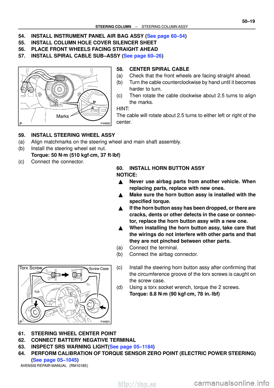
F44800
Marks
F44801
Torx ScrewScrew Case
±
STEERING COLUMN STEERING COLUMN ASSY
50±19
AVENSIS REPAIR MANUAL (RM1018E)
54.INSTALL INSTRUMENT PANEL AIR BAG ASSY (See page 60±54)
55. INSTALL COLUMN HOLE COVER SILENCER SHEET
56. PLACE FRONT WHEELS FACING STRAIGHT AHEAD
57.INSTALL SPIRAL CABLE SUB±ASSY (See page 60±26)
58. CENTER SPIRAL CABLE
(a) Check that the front wheels are facing straight ahead.
(b) Turn the cable counterclockwise by hand until it becomesharder to turn.
(c) Then rotate the cable clockwise about 2.5 turns to align the marks.
HINT:
The cable will rotate about 2.5 turns to either left or right of the
center.
59. INSTALL STEERING WHEEL ASSY
(a) Align matchmarks on the steering wheel and main shaft assembly.
(b) Install the steering wheel set nut. Torque: 50 N´m (510 kgf´cm, 37 ft´lbf)
(c) Connect the connector.
60. INSTALL HORN BUTTON ASSY
NOTICE:
�Never use airbag parts from another vehicle. When
replacing parts, replace with new ones.
�Make sure the horn button assy is installed with the
specified torque.
�If the horn button assy has been dropped, or there are
cracks, dents or other defects in the case or connec-
tor, replace the horn button assy with a new one.
�When installing the horn button assy, take care that
the wirings do not interfere with other parts and that
they are not pinched between other parts.
(a) Connect the terminal.
(b) Connect the airbag connector.
(c) Install the steering horn button assy after confirming that the circumference groove of the torx screws is caught on
the screw case.
(d) Using a torx socket wrench, torque the 2 screws. Torque: 8.8 N´m (90 kgf´cm, 78 in.´lbf)
61. STEERING WHEEL CENTER POINT
62. CONNECT BATTERY NEGATIVE TERMINAL
63.INSPECT SRS WARNING LIGHT(See page 05±1184)
64. PERFORM CALIBRATION OF TORQUE SENSOR ZERO POINT (ELECTRIC POWER STEERING) (See page 05±1045)
http://vnx.su
Page 1444 of 2234
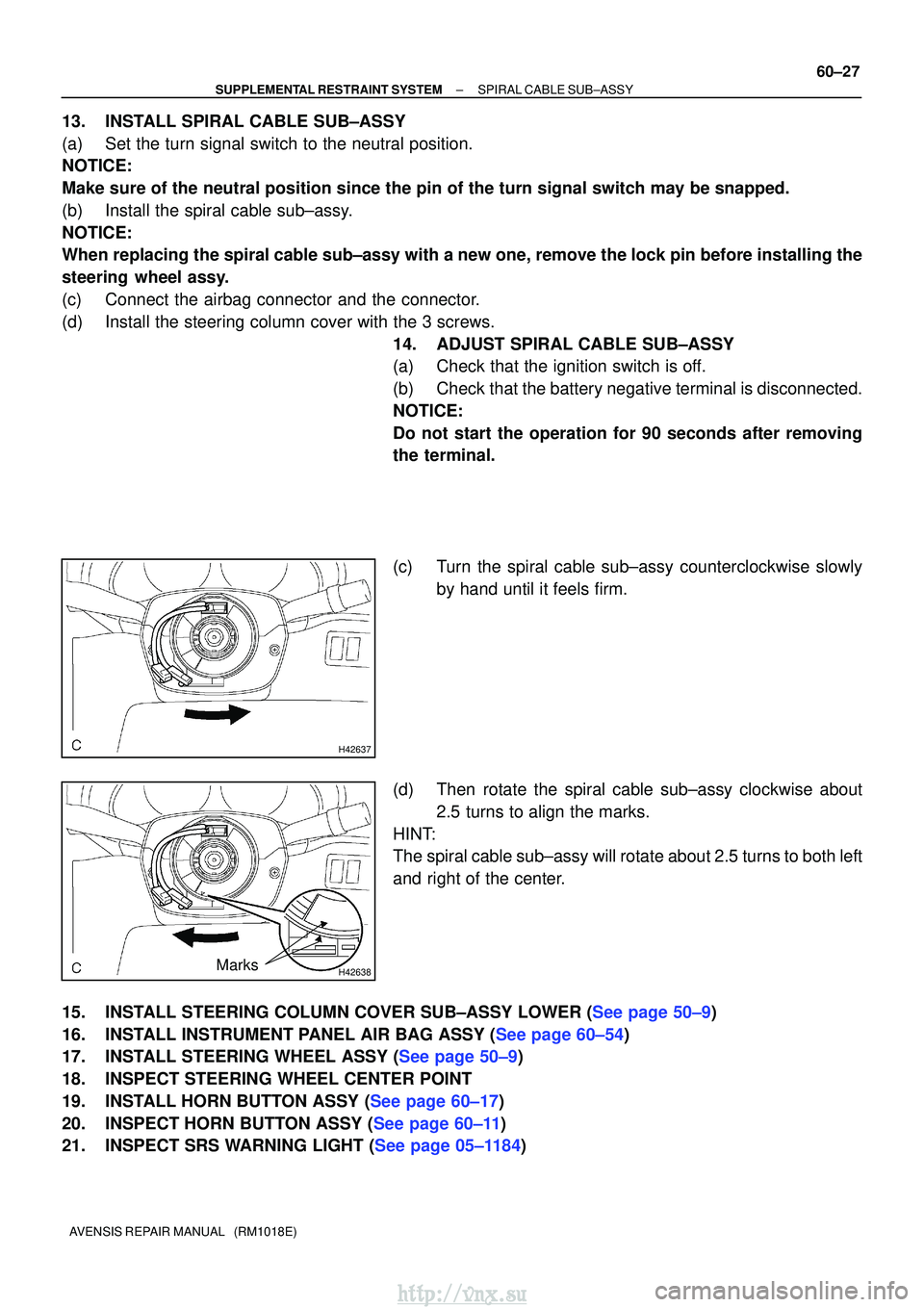
H42637
H42638Marks
±
SUPPLEMENTAL RESTRAINT SYSTEM SPIRAL CABLE SUB±ASSY
60±27
AVENSIS REPAIR MANUAL (RM1018E)
13. INSTALL SPIRAL CABLE SUB±ASSY
(a) Set the turn signal switch to the neutral position.
NOTICE:
Make sure of the neutral position since the pin of the turn signal switc\
h may be snapped.
(b) Install the spiral cable sub±assy.
NOTICE:
When replacing the spiral cable sub±assy with a new one, remove the l\
ock pin before installing the
steering wheel assy.
(c) Connect the airbag connector and the connector.
(d) Install the steering column cover with the 3 screws.
14. ADJUST SPIRAL CABLE SUB±ASSY
(a) Check that the ignition switch is off.
(b) Check that the battery negative terminal is disconnected.
NOTICE:
Do not start the operation for 90 seconds after removing
the terminal.
(c) Turn the spiral cable sub±assy counterclockwise slowlyby hand until it feels firm.
(d) Then rotate the spiral cable sub±assy clockwise about 2.5 turns to align the marks.
HINT:
The spiral cable sub±assy will rotate about 2.5 turns to both left
and right of the center.
15.INSTALL STEERING COLUMN COVER SUB±ASSY LOWER (See page 50±9)
16.INSTALL INSTRUMENT PANEL AIR BAG ASSY (See page 60±54)
17.INSTALL STEERING WHEEL ASSY (See page 50±9)
18. INSPECT STEERING WHEEL CENTER POINT
19.INSTALL HORN BUTTON ASSY (See page 60±17)
20.INSPECT HORN BUTTON ASSY (See page 60±11)
21.INSPECT SRS WARNING LIGHT (See page 05±1184)
http://vnx.su
Page 1446 of 2234
60±2
±
SUPPLEMENTAL RESTRAINT SYSTEM SUPPLEMENTAL RESTRAINT SYSTEM
AVENSIS REPAIR MANUAL (RM1018E)
�When the negative (±) terminal cable is disconnected from the batte\
ry, the memory of the clock
and audio system will be canceled. So before starting work, make a record o\
f the contents mem-
orized in the audio memory system. When work is finished, reset the audio syst\
ems as they
were before and adjust the clock. To avoid erasing the memory in each memory system, never
use a back±up power supply from outside the vehicle.
�If the vehicle is equipped with a mobile communication system, refer to the precaution in the
INTRODUCTION section.
http://vnx.su
Page 1488 of 2234
650SY±01
I35230
±
LIGHTINGFOG LAMP ASSY LH
65±23
AVENSIS REPAIR MANUAL (RM1018E)
ADJUSTMENT
1.PUT VEHICLE THESE CONDITIONS
(a)Tire inflation pressure is within the specified value. (See page 28±1)
(b) Start the engine.
2. ADJUST FOG LIGHT AIM
(a) The fog light aim can be adjusted by turning the aimingscrew in the vertical direction.
HINT:
The optical aim moves upward when turning the screwdriver
clockwise and moves downward when turning the screwdriver
center clockwise.
3. CHECK FOG LIGHT AIM
http://vnx.su
Page 1496 of 2234
I35248
V LH Line
V RH Line
V Line90�
3 m (9.84 ft)
I37308
Low Beam:V LH Line
V RH Line
30mm
(1.18 in.) 84 mm
(3.3 in.)
H Line6mm
(0.23 in.)
I37102
High Beam:V LH Line
V RH Line
H Line
I35802Adjusting Bolt A
Adjusting Bolt B
65±20
±
LIGHTING HEADLAMP UNIT LH
AVENSIS REPAIR MANUAL (RM1018E)
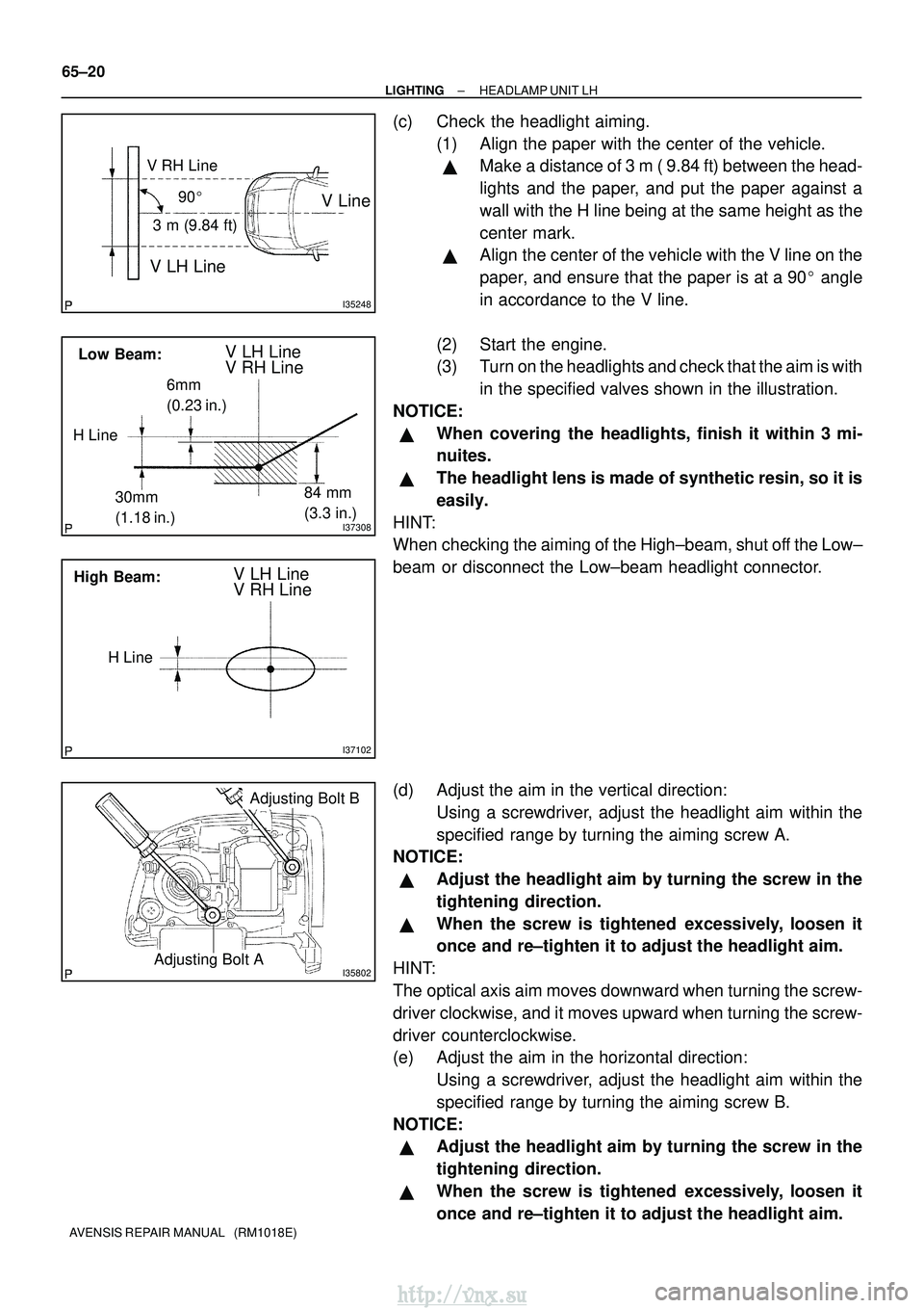
(c) Check the headlight aiming. (1) Align the paper with the center of the vehicle.
�Make a distance of 3 m ( 9.84 ft) between the head-
lights and the paper, and put the paper against a
wall with the H line being at the same height as the
center mark.
�Align the center of the vehicle with the V line on the
paper, and ensure that the paper is at a 90 � angle
in accordance to the V line.
(2) Start the engine.
(3) Turn on the headlights and check that the aim is with in the specified valves shown in the illustration.
NOTICE:
�When covering the headlights, finish it within 3 mi-
nuites.
�The headlight lens is made of synthetic resin, so it is
easily.
HINT:
When checking the aiming of the High±beam, shut off the Low±
beam or disconnect the Low±beam headlight connector.
(d) Adjust the aim in the vertical direction: Using a screwdriver, adjust the headlight aim within the
specified range by turning the aiming screw A.
NOTICE:
�Adjust the headlight aim by turning the screw in the
tightening direction.
�When the screw is tightened excessively, loosen it
once and re±tighten it to adjust the headlight aim.
HINT:
The optical axis aim moves downward when turning the screw-
driver clockwise, and it moves upward when turning the screw-
driver counterclockwise.
(e) Adjust the aim in the horizontal direction: Using a screwdriver, adjust the headlight aim within the
specified range by turning the aiming screw B.
NOTICE:
�Adjust the headlight aim by turning the screw in the
tightening direction.
�When the screw is tightened excessively, loosen it
once and re±tighten it to adjust the headlight aim.
http://vnx.su