Page 1672 of 2234

B65859
Slide Motor
ClockwiseCounter±
clockwiseDriving Axis
B65859
Front Vertical
Motor
Clockwise
Counter±clockwise
Driving Axis
B65859
Lifter Motor
Clockwise
Counter±
clockwise
Driving Axis
72±8
±
SEAT FRONT POWER SEAT CONTROL SYSTEM
AVENSIS REPAIR MANUAL (RM1018E)
4. INSPECT POWER SEAT MOTOR ASSY
(a) Inspect operation of the slide motor. (1) Check that the motor rotates smoothly when the
battery is connected to the motor connector termi-
nals.
Standard:
Tester ConnectionOperational Direction
Battery positive voltage �1
Battery negative voltage �2Clockwise
Battery positive voltage �2
Battery negative voltage �1Counterclockwise
If the result is not as specified, replace the motor assy.
(b) Driver side seat:
Inspect operation of the front vertical motor.
(1) Check that the motor rotates smoothly when thebattery is connected to the front vertical motor con-
nector terminals.
Standard:
Tester ConnectionOperational Direction
Battery positive voltage �1
Battery negative voltage �2Clockwise
Battery positive voltage �2
Battery negative voltage �1Counterclockwise
If the result is not as specified, replace the motor assy.
(c) Driver side seat:
Inspect operation of the lifter motor.
(1) Check that the motor rotates smoothly when thebattery is connected to the lifter motor connector
terminals.
Standard:
Tester ConnectionOperational Direction
Battery positive voltage �1
Battery negative voltage �2Clockwise
Battery positive voltage �2
Battery negative voltage �1Counterclockwise
If the result is not as specified, replace the motor assy.
http://vnx.su
Page 1673 of 2234

B65859
Clockwise
Counter±
clockwise
Reclining Motor
Driving Axis
B65448
Clockwise
Driving Axis Counter±clockwise Lumbar Support
Adjuster Motor
±
SEAT FRONT POWER SEAT CONTROL SYSTEM
72±9
AVENSIS REPAIR MANUAL (RM1018E)
(d) Inspect operation of the reclining motor.
(1) Check that the motor rotates smoothly when thebattery is connected to the reclining motor connec-
tor terminals.
Standard:
Tester ConnectionOperational Direction
Battery positive voltage �1
Battery negative voltage �2Clockwise
Battery positive voltage �2
Battery negative voltage �1Counterclockwise
If the result is not as specified, replace the motor assy.
5. Driver side seat:
INSPECT LUMBAR SUPPORT ADJUSTER ASSY
(a) Inspect operation of the motor. (1) Check that the motor rotates smoothly when thebattery is connected to the lumber support adjuster
motor connector terminals.
Standard:
Tester ConnectionOperational Direction
Battery positive voltage �1
Battery negative voltage �2Clockwise
Battery positive voltage �2
Battery negative voltage �1Counterclockwise
If the result is not as specified, replace the adjuster assy.
http://vnx.su
Page 1718 of 2234

9. INSPECT BACK DOOR LOCK ASSY (SEDAN MODELS)
(a) Check operation")
B66817
Full±latch
Open±latch
73±10
±
THEFT DETERRENT & DOOR LOCK POWER DOOR LOCK CONTROL SYSTEM
AVENSIS REPAIR MANUAL (RM1018E)
9. INSPECT BACK DOOR LOCK ASSY (SEDAN MODELS)
(a) Check operation of the door lock.
(1) Using a screwdriver, push the latch in order to putthe back door lock in the locked condition (full±latch
position).
(2) Apply battery voltage to the door lock and check op-
eration of the latch.
Standard:
Measurement ConditionSpecified Condition
Battery positive (+) � Terminal 1
Battery negative (±) � Terminal 3Latch turns to open±latch position
If the result is not as specified, replace the door lock assy.
(b) Apply battery voltage to the door lock motor and check
motor operation.
Standard:
Measurement ConditionSpecified Condition
Battery positive (+) � Terminal 3
Battery negative (±) � Terminal 1Clockwise �Motor in normal rotation �
Battery positive (+) � Terminal 1
Battery negative (±) � Terminal 3Counterclockwise (Motor in reverse rota-
tion)
If the result is not as specified, replace the door lock assy.
(c) Check the resistance of the courtesy switch.Standard:
Tester ConnectionDoor Lock Latch PositionSpecified Condition
23Open±latch positionBelow 1 �2 ± 3Full±latch position10 k�or higher
If the result is not as specified, replace the door lock assy.
http://vnx.su
Page 1719 of 2234

10. INSPECT BACK DOOR LOCK ASSY (WAGON
MODELS)
(a) Check operation")
B66815
Full±latch
Open±latch
±
THEFT DETERRENT & DOOR LOCK POWER DOOR LOCK CONTROL SYSTEM
73±11
AVENSIS REPAIR MANUAL (RM1018E)
10. INSPECT BACK DOOR LOCK ASSY (WAGON
MODELS)
(a) Check operation of the door lock.
(1) Using a screwdriver, push the latch in order to putthe back door lock in the locked condition (full±latch
position).
(2) Apply battery voltage to the door lock and check op-
eration of the latch.
Standard:
Measurement ConditionSpecified Condition
Battery positive (+) � Terminal 4
Battery negative (±) � Terminal 3Latch turns to open±latch position
If the result is not as specified, replace the door lock assy.
(b) Apply battery voltage to the door lock motor and check
motor operation.
Standard:
Measurement ConditionSpecified Condition
Battery positive (+) � Terminal 4
Battery negative (±) � Terminal 3Clockwise �Motor in normal rotation �
Battery positive (+) � Terminal 3
Battery negative (±) � Terminal 4Counterclockwise (Motor in reverse rota-
tion)
If the result is not as specified, replace the door lock assy.
(c) Check the resistance of the courtesy switch.Standard:
Tester ConnectionDoor Lock Latch PositionSpecified Condition
12Open±latch positionBelow 1 �1 ± 2Full±latch position10 k�or higher
If the result is not as specified, replace the door lock assy.
http://vnx.su
Page 1720 of 2234

B66816
Full±latch
Open±latch
B68460
LOCKUNLOCK
Door Control Switch
123 6 7 45 8918 19 22 23
20 21 24
10 11
14 15
12
13 16 17
73±12
±
THEFT DETERRENT & DOOR LOCK POWER DOOR LOCK CONTROL SYSTEM
AVENSIS REPAIR MANUAL (RM1018E)
11. INSPECT BACK DOOR LOCK ASSY (LIFT BACK
MODELS)
(a) Check operation of the door lock.
(1) Using a screwdriver, push the latch in order to putthe back door lock in the locked condition (full±latch
position).
(2) Apply battery voltage to the door lock and check op-
eration of the latch.
Standard:
Measurement ConditionSpecified Condition
Battery positive (+) � Terminal 4
Battery negative (±) � Terminal 3Latch turns to open±latch position
If the result is not as specified, replace the door lock assy.
(b) Apply battery voltage to the door lock motor and check
motor operation.
Standard:
Measurement ConditionSpecified Condition
Battery positive (+) � Terminal 4
Battery negative (±) � Terminal 3Clockwise �Motor in normal rotation �
Battery positive (+) � Terminal 3
Battery negative (±) � Terminal 4Counterclockwise (Motor in reverse rota-
tion)
If the result is not as specified, replace the door lock assy.
(c) Check the resistance of the courtesy switch.Standard:
Tester ConnectionDoor Lock Latch PositionSpecified Condition
12Open±latch positionBelow 1 �1 ± 2Full±latch position10 k�or higher
If the result is not as specified, replace the door lock assy.
12. INSPECT POWER WINDOW REGULATOR MASTER
SWITCH ASSY
(a) Check the resistance of the door control switch. Standard:
Tester ConnectionDoor Lock PositionSpecified Condition
7 ± 8LockBelow 1 �
7 ± 8OFF10 k�or higher5 ± 7OFF10 k�or higher
5 ± 7UnlockBelow 1 �
If the result is not as specified, replace the switch assy.
http://vnx.su
Page 1827 of 2234
B66541Claw
Claw
B66529
ClawClaw
B50596
90�
±
EXTERIOR/INTERIOR TRIM ROOF HEADLINING ASSY (LIFTBACK MODELS)
76±49
AVENSIS REPAIR MANUAL (RM1018E)
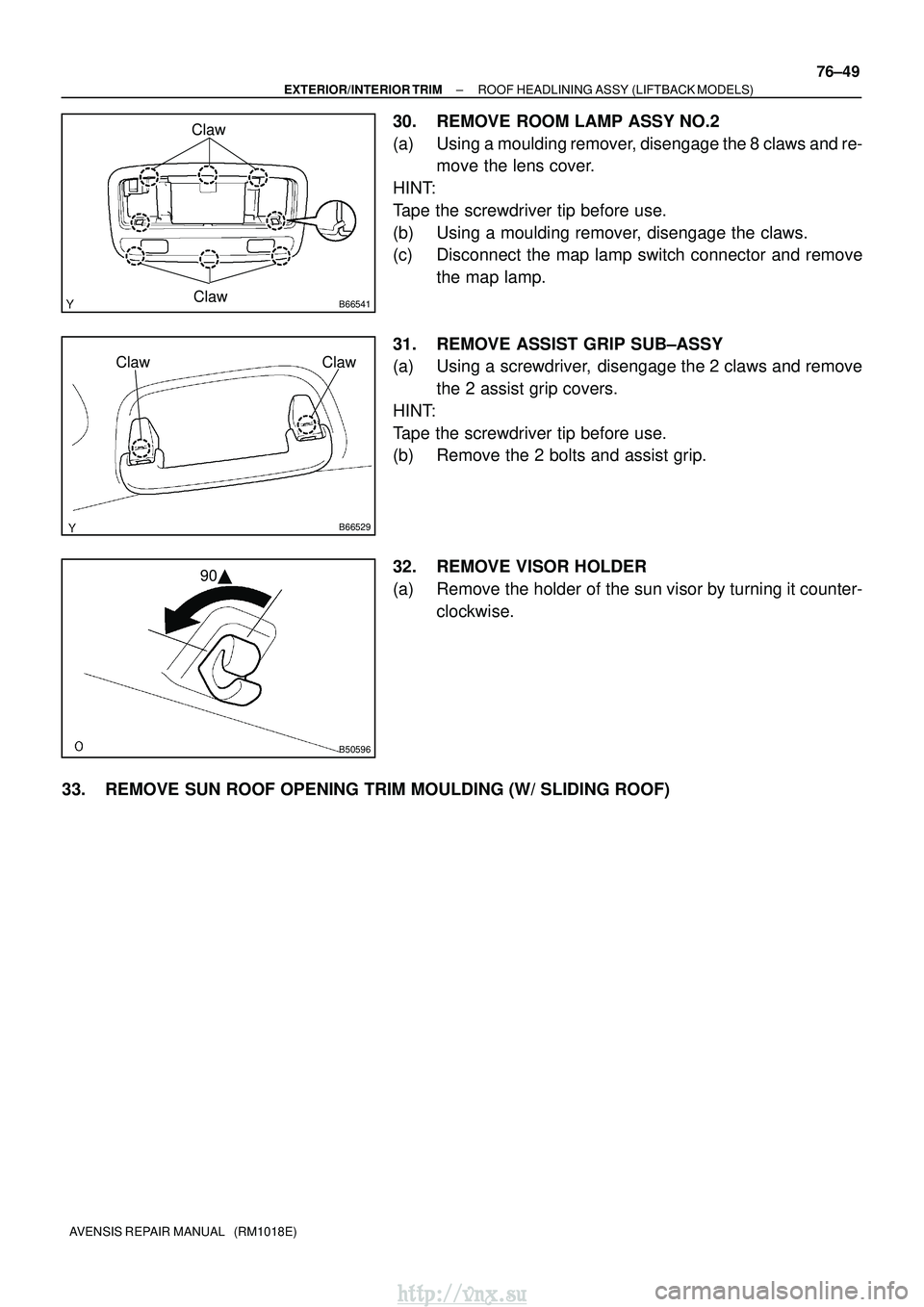
30. REMOVE ROOM LAMP ASSY NO.2
(a) Using a moulding remover, disengage the 8 claws and re-
move the lens cover.
HINT:
Tape the screwdriver tip before use.
(b) Using a moulding remover, disengage the claws.
(c) Disconnect the map lamp switch connector and remove the map lamp.
31. REMOVE ASSIST GRIP SUB±ASSY
(a) Using a screwdriver, disengage the 2 claws and remove the 2 assist grip covers.
HINT:
Tape the screwdriver tip before use.
(b) Remove the 2 bolts and assist grip.
32. REMOVE VISOR HOLDER
(a) Remove the holder of the sun visor by turning it counter- clockwise.
33. REMOVE SUN ROOF OPENING TRIM MOULDING (W/ SLIDING ROOF)
http://vnx.su
Page 1836 of 2234
B66529
ClawClaw
B50596
90�
B66556
Clip
w/ Sliding Roof
w/o Sliding Roof
76±40
±
EXTERIOR/INTERIOR TRIM ROOF HEADLINING ASSY (SEDAN MODELS)
AVENSIS REPAIR MANUAL (RM1018E)
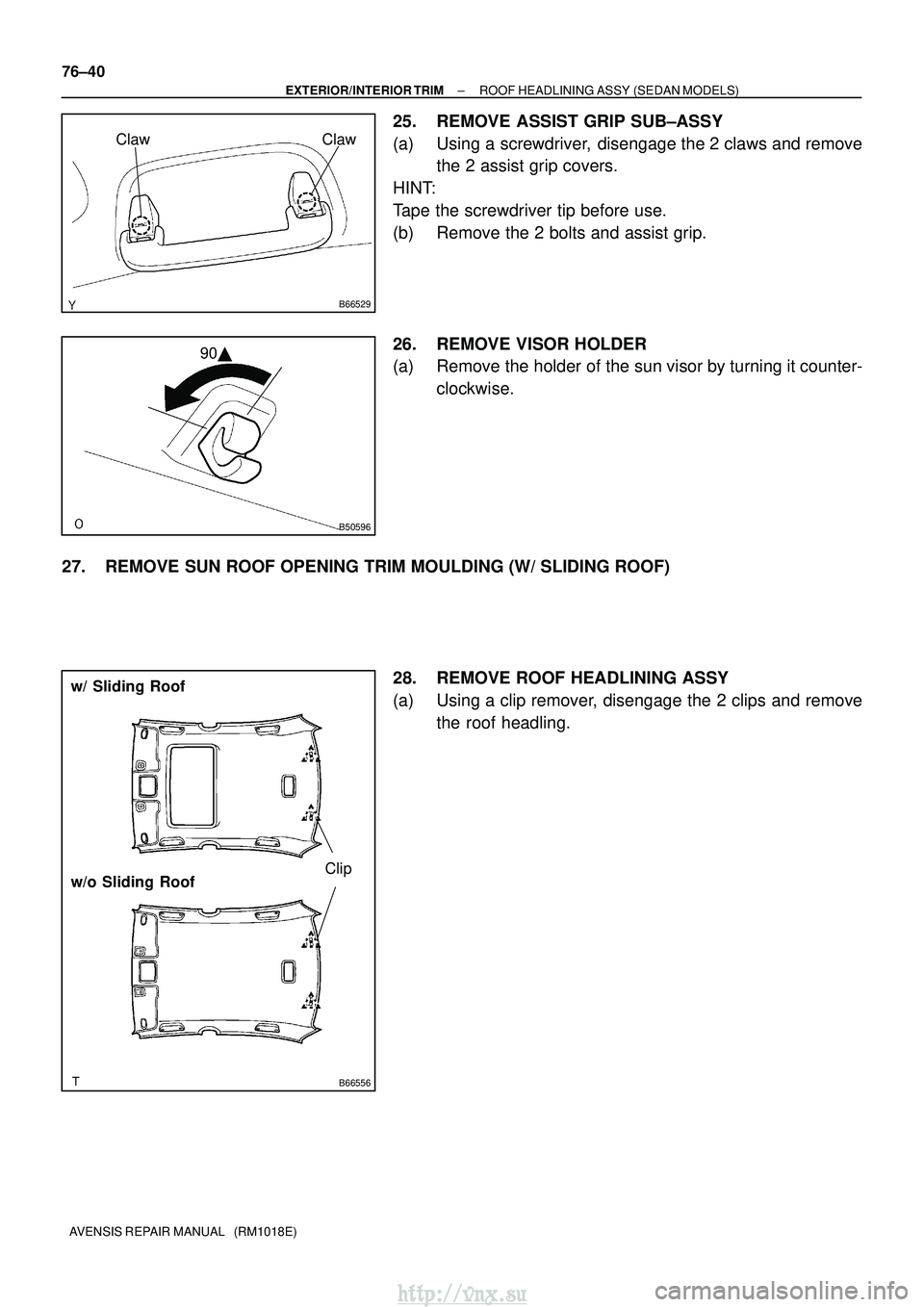
25. REMOVE ASSIST GRIP SUB±ASSY
(a) Using a screwdriver, disengage the 2 claws and remove the 2 assist grip covers.
HINT:
Tape the screwdriver tip before use.
(b) Remove the 2 bolts and assist grip.
26. REMOVE VISOR HOLDER
(a) Remove the holder of the sun visor by turning it counter- clockwise.
27. REMOVE SUN ROOF OPENING TRIM MOULDING (W/ SLIDING ROOF) 28. REMOVE ROOF HEADLINING ASSY
(a) Using a clip remover, disengage the 2 clips and removethe roof headling.
http://vnx.su
Page 1846 of 2234

76±59
AVENSIS REPAIR MANUAL (RM1018E)
37. REMOVE MAP LAMP ASSY
(a) Using a")
A79919
Claw
Claw
B66541Claw
Claw
B66529
ClawClaw
B50596
90�
±
EXTERIOR/INTERIOR TRIM ROOF HEADLINING ASSY (WAGON MODELS)
76±59
AVENSIS REPAIR MANUAL (RM1018E)
37. REMOVE MAP LAMP ASSY
(a) Using a screwdriver, disengage the 6 claws and remove
the lens cover.
HINT:
Tape the screwdriver tip before use.
(b) Remove the 2 screws.
(c) Using a moulding remover, disengage the claws.
(d) Disconnect the map lamp switch connector and sliding roof switch connector, and remove the map lamp.
38. REMOVE ROOM LAMP ASSY NO.2
(a) Using a moulding remover, disengage the 8 claws and re- move the lens cover.
HINT:
Tape the screwdriver tip before use.
(b) Using a moulding remover, disengage the claws.
(c) Disconnect the map lamp switch connector and remove the map lamp.
39. REMOVE ASSIST GRIP SUB±ASSY
(a) Using a screwdriver, disengage the 2 claws and remove the 2 assist grip covers.
HINT:
Tape the screwdriver tip before use.
(b) Remove the 2 bolts and assist grip.
40. REMOVE VISOR HOLDER
(a) Remove the holder of the sun visor by turning it counter- clockwise.
41. REMOVE SUN ROOF OPENING TRIM MOULDING (W/ SLIDING ROOF)
http://vnx.su