Page 786 of 2234
EM1628
EM2011
EM2538
±
ENGINE MECHANICAL PARTIAL ENGINE ASSY (1ZZ±FE/3ZZ±FE)
14±13
1ZZ±FE,3ZZ±FE ENGINE REPAIR MANUAL
(RM923E)
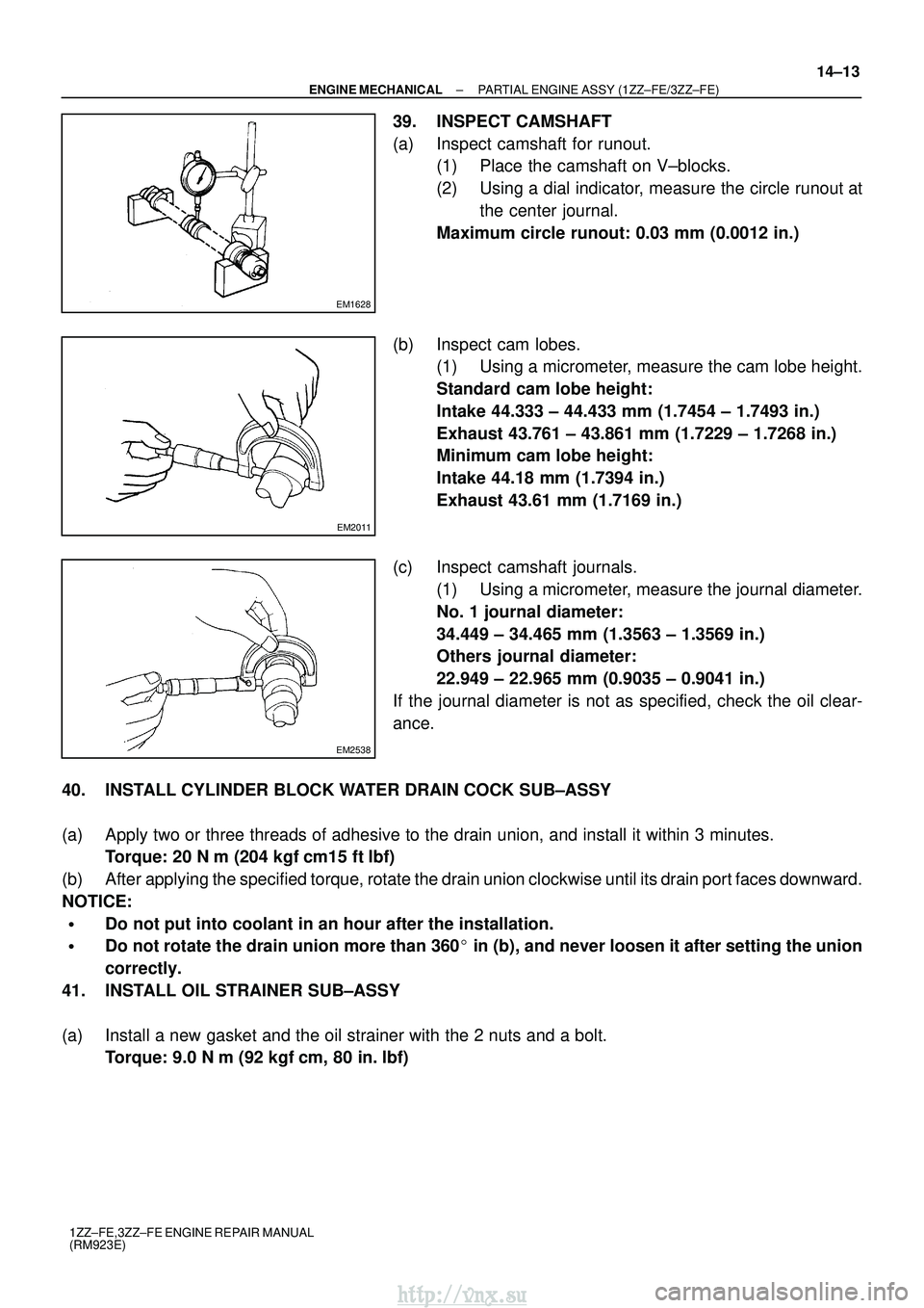
39. INSPECT CAMSHAFT
(a) Inspect camshaft for runout.
(1) Place the camshaft on V±blocks.
(2) Using a dial indicator, measure the circle runout at
the center journal.
Maximum circle runout: 0.03 mm (0.0012 in.)
(b) Inspect cam lobes. (1) Using a micrometer, measure the cam lobe height.
Standard cam lobe height:
Intake 44.333 ± 44.433 mm (1.7454 ± 1.7493 in.)
Exhaust 43.761 ± 43.861 mm (1.7229 ± 1.7268 in.)
Minimum cam lobe height:
Intake 44.18 mm (1.7394 in.)
Exhaust 43.61 mm (1.7169 in.)
(c) Inspect camshaft journals. (1) Using a micrometer, measure the journal diameter.
No. 1 journal diameter:
34.449 ± 34.465 mm (1.3563 ± 1.3569 in.)
Others journal diameter:
22.949 ± 22.965 mm (0.9035 ± 0.9041 in.)
If the journal diameter is not as specified, check the oil clear-
ance.
40. INSTALL CYLINDER BLOCK WATER DRAIN COCK SUB±ASSY
(a) Apply two or three threads of adhesive to the drain union, and install i\
t within 3 minutes. Torque: 20 N �m (204 kgf� cm15 ft�lbf)
(b) After applying the specified torque, rotate the drain union clockwise until i\
ts drain port faces downward.
NOTICE:
�Do not put into coolant in an hour after the installation.
�Do not rotate the drain union more than 360� in (b), and never loosen it after setting the union
correctly.
41. INSTALL OIL STRAINER SUB±ASSY
(a) Install a new gasket and the oil strainer with the 2 nuts and a bolt. Torque: 9.0 N �m (92 kgf �cm, 80 in. �lbf)
http://vnx.su
Page 793 of 2234
A62837SST
A62180
DisconnectHook
Pin Turn
A62181
Plunger
Turn
Push
A10085
A62179
A
ABB
B
B
14±20
±
ENGINE MECHANICAL PARTIAL ENGINE ASSY (1ZZ±FE/3ZZ±FE)
1ZZ±FE,3ZZ±FE ENGINE REPAIR MANUAL
(RM923E)
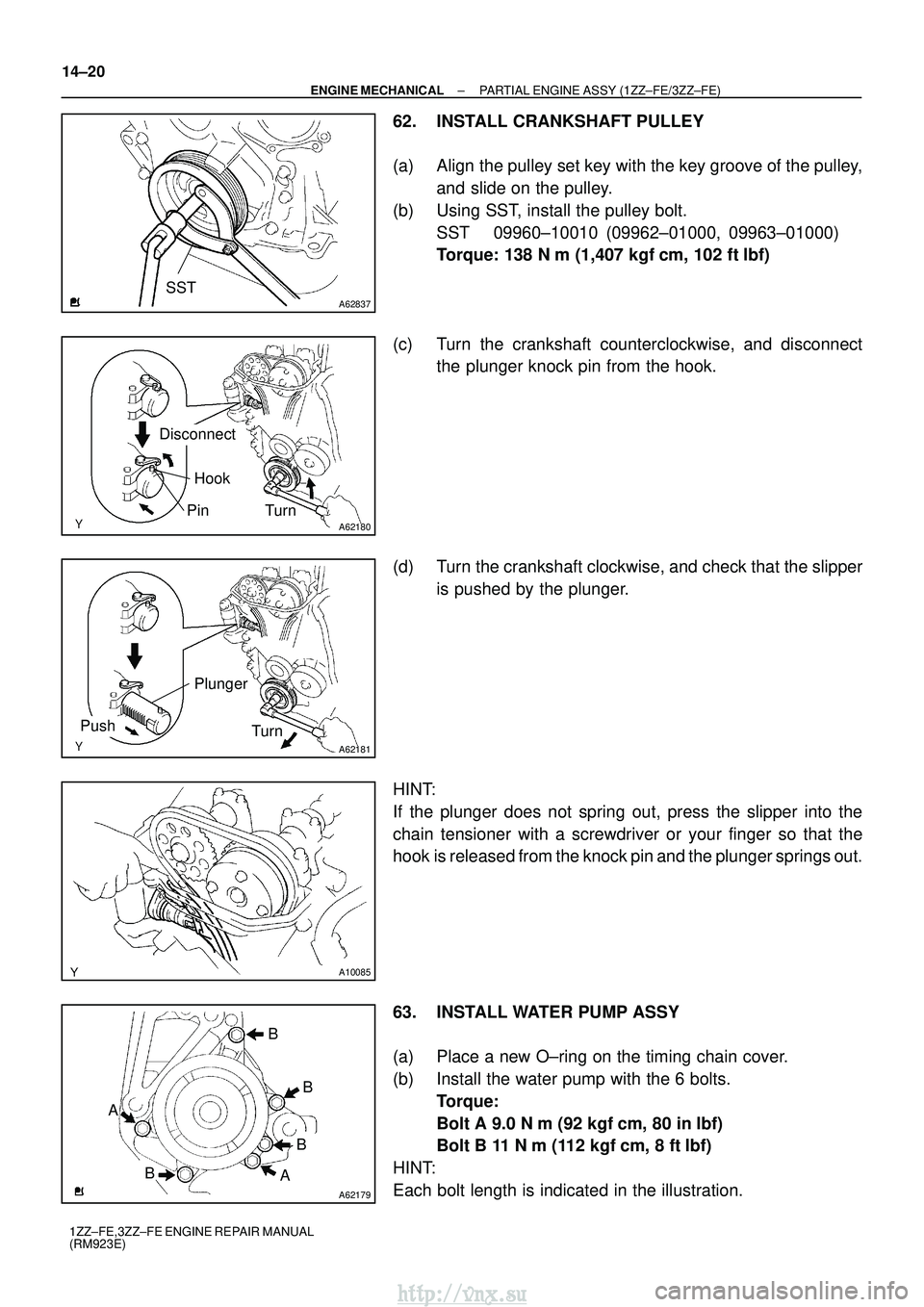
62. INSTALL CRANKSHAFT PULLEY
(a) Align the pulley set key with the key groove of the pulley, and slide on the pulley.
(b) Using SST, install the pulley bolt. SST 09960±10010 (09962±01000, 09963±01000)
Torque: 138 N� m (1,407 kgf�cm, 102 ft� lbf)
(c) Turn the crankshaft counterclockwise, and disconnect the plunger knock pin from the hook.
(d) Turn the crankshaft clockwise, and check that the slipper is pushed by the plunger.
HINT:
If the plunger does not spring out, press the slipper into the
chain tensioner with a screwdriver or your finger so that the
hook is released from the knock pin and the plunger springs out.
63. INSTALL WATER PUMP ASSY
(a) Place a new O±ring on the timing chain cover.
(b) Install the water pump with the 6 bolts. Torque:
Bolt A 9.0 N� m (92 kgf�cm, 80 in� lbf)
Bolt B 11 N� m (112 kgf�cm, 8 ft� lbf)
HINT:
Each bolt length is indicated in the illustration.
http://vnx.su
Page 798 of 2234
A62185
MarkMark
Mark Timing Chain
Cover Surface
Groove
A62177
Raise
Push
Hook
Pin
A62178
Push
A62180
Disconnect
Hook
Pin Turn
±
ENGINE MECHANICAL PARTIAL ENGINE ASSY (1ZZ±FE/3ZZ±FE)
14±25
1ZZ±FE,3ZZ±FE ENGINE REPAIR MANUAL
(RM923E)
(t) Check the match marks on the timing chain and camshaft
timing sprockets, and then the alignment of the pulley
groove with timing mark of the chain cover as shown in the
illustration.
(u) Install chain tensioner. (1) Check the O±ring is clean, and set the hook asshown in the illustration.
(2) Apply engine oil to the chain tensioner and install it.
Torque: 9.0 N� m (92 kgf�cm, 80 in� lbf)
NOTICE:
When installing the tensioner, set the hook again if the
hook release the plunger.
(3) Turn the crankshaft counterclockwise, and discon-nect the plunger knock pin from the hook.
http://vnx.su
Page 799 of 2234
A62181
PlungerTurn
Push
A10085
A62182
Seal Packing
14±26
±
ENGINE MECHANICAL PARTIAL ENGINE ASSY (1ZZ±FE/3ZZ±FE)
1ZZ±FE,3ZZ±FE ENGINE REPAIR MANUAL
(RM923E)
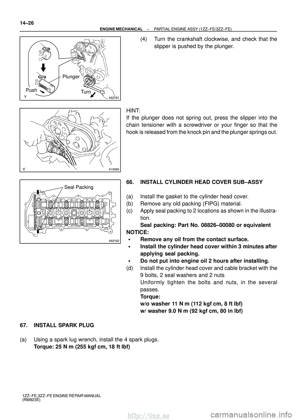
(4) Turn the crankshaft clockwise, and check that the slipper is pushed by the plunger.
HINT:
If the plunger does not spring out, press the slipper into the
chain tensioner with a screwdriver or your finger so that the
hook is released from the knock pin and the plunger springs out.
66. INSTALL CYLINDER HEAD COVER SUB±ASSY
(a) Install the gasket to the cylinder head cover.
(b) Remove any old packing (FIPG) material.
(c) Apply seal packing to 2 locations as shown in the illustra- tion.
Seal packing: Part No. 08826±00080 or equivalent
NOTICE:
�Remove any oil from the contact surface.
�Install the cylinder head cover within 3 minutes after
applying seal packing.
�Do not put into engine oil 2 hours after installing.
(d) Install the cylinder head cover and cable bracket with the 9 bolts, 2 seal washers and 2 nuts
Uniformly tighten the bolts and nuts, in the several
passes.
Torque:
w/o washer 11 N� m (112 kgf�cm, 8 ft� lbf)
w/ washer 9.0 N �m (92 kgf �cm, 80 in� lbf)
67. INSTALL SPARK PLUG
(a) Using a spark lug wrench, install the 4 spark plugs. Torque: 25 N �m (255 kgf� cm, 18 ft�lbf)
http://vnx.su
Page 841 of 2234
190AA±01
A62753
SST
1 ± BSST
1 ± A
A62754SST 2
A62755
SST
1 ± A
A62756
SST
1 ± A
SST
1 ± B
19±10
±
STARTING & CHARGING GENERATOR ASSY (1ZZ±FE/3ZZ±FE)
1ZZ±FE,3ZZ±FE ENGINE REPAIR MANUAL
(RM923E)
OVERHAUL
1. REMOVE GENERATOR PULLEY SST 09820±63010 (09820±06010, 09820±06020)
HINT:
SST1 ± A, B09820±06010
SST209820±06020
(a) Hold SST 1 ± A with a torque wrench, and tighten SST 1 ± B clockwise to the specified torque.
Torque: 39 N �m (398 kgf� cm, 29 ft�lbf)
NOTICE:
Check that SST is secured to the rotor shaft.
(b) Mount SST 2 in a vise.
(c) Insert SST 1 ± A, B into SST 2, and attach the pulley nut to SST 2.
(d) To loosen the pulley nut, turn SST 1 ± A in the direction shown in the illustration.
NOTICE:
To prevent damage to the rotor shaft, do not loosen the
pulley nut more than one±half of a turn.
(e) Remove the alternator form SST 2.
(f) Turn SST 1 ± B, and remove SST 1 ± A, B.
(g) Remove the pulley nut and pulley.
http://vnx.su
Page 845 of 2234
A62753
SST
1 ± BSST
1 ± A
A62754SST 2
A62765
SST
1 ± A
19±14
±
STARTING & CHARGING GENERATOR ASSY (1ZZ±FE/3ZZ±FE)
1ZZ±FE,3ZZ±FE ENGINE REPAIR MANUAL
(RM923E)
(b) Install the rear end cover with the 2 nuts. Torque: 4.4 N �m (45 kgf �cm, 39 in. �lbf)
(c) Install the terminal plate with the screw and nut.
Torque:
Bolt 3.9 N �m (40 kgf �cm, 35 in. �lbf)
Nut 4.4 N� m (45 kgf�cm, 39 in. �lbf)
(d) Install the terminal insulator withe the nut.
Torque: 4.1 N �m (42 kgf �cm, 36 in. �lbf)
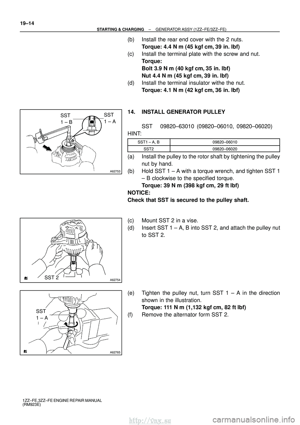
14. INSTALL GENERATOR PULLEY SST 09820±63010 (09820±06010, 09820±06020)
HINT:
SST1 ± A, B09820±06010
SST209820±06020
(a) Install the pulley to the rotor shaft by tightening the pulley nut by hand.
(b) Hold SST 1 ± A with a torque wrench, and tighten SST 1 ± B clockwise to the specified torque.
Torque: 39 N �m (398 kgf� cm, 29 ft�lbf)
NOTICE:
Check that SST is secured to the pulley shaft.
(c) Mount SST 2 in a vise.
(d) Insert SST 1 ± A, B into SST 2, and attach the pulley nut to SST 2.
(e) Tighten the pulley nut, turn SST 1 ± A in the direction shown in the illustration.
Torque: 111 N� m (1,132 kgf�cm, 82 ft �lbf)
(f) Remove the alternator form SST 2.
http://vnx.su
Page 851 of 2234
A62224
A37017
A37020
A62225
Free
Lock
A33580
±
STARTING & CHARGING STARTER ASSY (1ZZ±FE/3ZZ±FE)
19±5
1ZZ±FE,3ZZ±FE ENGINE REPAIR MANUAL
(RM923E)
(b) Using an ohmmeter, check that there is no continuity be-
tween the field coil end and field frame.
8. INSPECT BRUSH
(a) Using a vernier calipers, measure the brush length. Standard length: 14 mm (0.551 in.)
Minimum length: 9 mm (0.354 in.)
9. INSPECT STARTER BRUSH HOLDER ASSY
(a) Using an ohmmeter, check that there is no continuity be- tween the positive (+) and negative (±) brush holders.
10. INSPECT STARTER CLUTCH SUB±ASSY
(a) Rotate the clutch pinion gear clockwise and check that it turns freely. Try to rotate the clutch pinion gear counter-
clockwise and check that it locks.
11. INSPECT MAGNET STARTER SWITCH ASSY
(a) Push in the plunger and check that it returns quickly to its original position.
http://vnx.su
Page 1099 of 2234
320VI±01
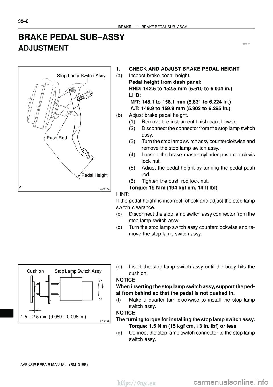
G23173
Stop Lamp Switch Assy
Push Rod Pedal Height
F43108
Stop Lamp Switch Assy
Cushion
1.5 ± 2.5 mm (0.059 ± 0.098 in.)
32±6
±
BRAKE BRAKE PEDAL SUB±ASSY
AVENSIS REPAIR MANUAL (RM1018E)
BRAKE PEDAL SUB±ASSY
ADJUSTMENT
1. CHECK AND ADJUST BRAKE PEDAL HEIGHT
(a) Inspect brake pedal height. Pedal height from dash panel:
RHD: 142.5 to 152.5 mm (5.610 to 6.004 in.)
LHD:
M/T: 148.1 to 158.1 mm (5.831 to 6.224 in.)
A/T: 149.9 to 159.9 mm (5.902 to 6.295 in.)
(b) Adjust brake pedal height. (1) Remove the instrument finish panel lower.
(2) Disconnect the connector from the stop lamp switchassy.
(3) Turn the stop lamp switch assy counterclokwise and remove the stop lamp switch assy.
(4) Loosen the brake master cylinder push rod clevis lock nut.
(5) Adjust the pedal height by turning the pedal push rod.
(6) Tighten the push rod lock nut.
Torque: 19 N �m (194 kgf� cm, 14 ft�lbf)
HINT:
If the pedal height is incorrect, check and adjust the stop lamp
switch clearance.
(c) Disconnect the stop lamp switch assy connector from the stop lamp switch assy.
(d) Turn the stop lamp switch assy counterclockwise and re- move the stop lamp switch assy.
(e) Insert the stop lamp switch assy until the body hits the cushion.
NOTICE:
When inserting the stop lamp switch assy, support the ped-
al from behind so that the pedal is not pushed in.
(f) Make a quarter turn clockwise to install the stop lamp
switch assy.
NOTICE:
The turning torque for installing the stop lamp switch assy.
Torque: 1.5 N� m (15 kgf�cm, 13 in. �lbf) or less
(g) Connect the stop lamp switch connector to the stop lamp switch assy.
http://vnx.su