Page 465 of 2234

A77395
Engine
Front
A77396
HookPinTurn
Disconnect
A77397
Push Turn
Plunger
±
ENGINE MECHANICALCAMSHAFT(1AZ±FSE)
14±245
AVENSIS REPAIR MANUAL (RM1018E)
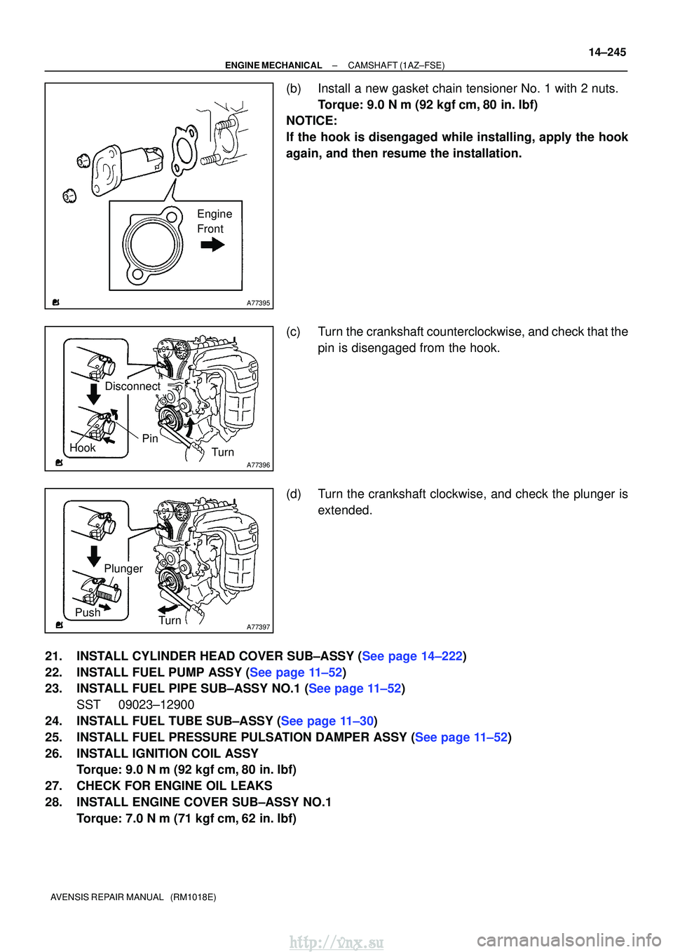
(b)Install a new gasket chain tensioner No. 1 with 2 nuts.
Torque: 9.0 N �m (92 kgf�cm,80 in. �lbf)
NOTICE:
If the hook is disengaged while installing, apply the hook
again, and then resume the installation.
(c)Turn the crankshaft counterclockwise, and check that the
pin is disengaged from the hook.
(d)Turn the crankshaft clockwise, and check the plunger is extended.
21.INSTALL CYLINDER HEAD COVER SUB±ASSY (See page 14±222)
22.INSTALL FUEL PUMP ASSY (See page 11±52)
23.INSTALL FUEL PIPE SUB±ASSY NO.1 (See page 11±52) SST 09023±12900
24.INSTALL FUEL TUBE SUB±ASSY (See page 11±30)
25.INSTALL FUEL PRESSURE PULSATION DAMPER ASSY (See page 11±52)
26. INSTALL IGNITION COIL ASSY Torque: 9.0 N �m (92 kgf �cm, 80 in. �lbf)
27. CHECK FOR ENGINE OIL LEAKS
28. INSTALL ENGINE COVER SUB±ASSY NO.1 Torque: 7.0 N �m (71 kgf �cm, 62 in. �lbf)
http://vnx.su
Page 483 of 2234
A64058
A64856
A60622
A01045
A64005
±
ENGINE MECHANICALCAMSHAFT(1ZZ±FE/3ZZ±FE)
14±65
AVENSIS REPAIR MANUAL (RM1018E)
6.DISCONNECT VENTILATION HOSE NO.2
(a)Disconnect the ventilation hose from the cylinder head
cover.
7.REMOVE CYLINDER HEAD COVER SUB±ASSY
(a)Remove the 9 bolts, 2 seal washers, 2 nuts, and 3 clamp brackets.
(b)Remove the cylinder head cover.
8.REMOVE ENGINE UNDER COVER SUB±ASSY NO.1 (See page 14±27)
9. REMOVE ENGINE ROOM COVER SIDE (See page 14±27)
10. REMOVE FAN AND GENERATOR V BELT
(a) Turn the V±ribbed belt tensioner clockwise slowly and loosen it. Then, remove the fan and generator V belt and
put back the V±ribbed belt tensioner carefully.
11. REMOVE ENGINE MOUNTING INSULATOR SUB±ASSY RH
(a) Place a wooden block on a jack underneath the engine. Remove the 4 bolts and 2 nuts and detach the engine
mounting insulator RH.
http://vnx.su
Page 488 of 2234

A62191
Advanced
Side Path
Retard
Side Path
A62192
Hold Pressure
Decompress Advanced
Side Path
Retard
Side Path
A62193
Straight Pin
Fringe Bolt
A62194
Straight Pin
Key Groove
14±70
±
ENGINE MECHANICAL CAMSHAFT (1ZZ±FE/3ZZ±FE)
AVENSIS REPAIR MANUAL (RM1018E)
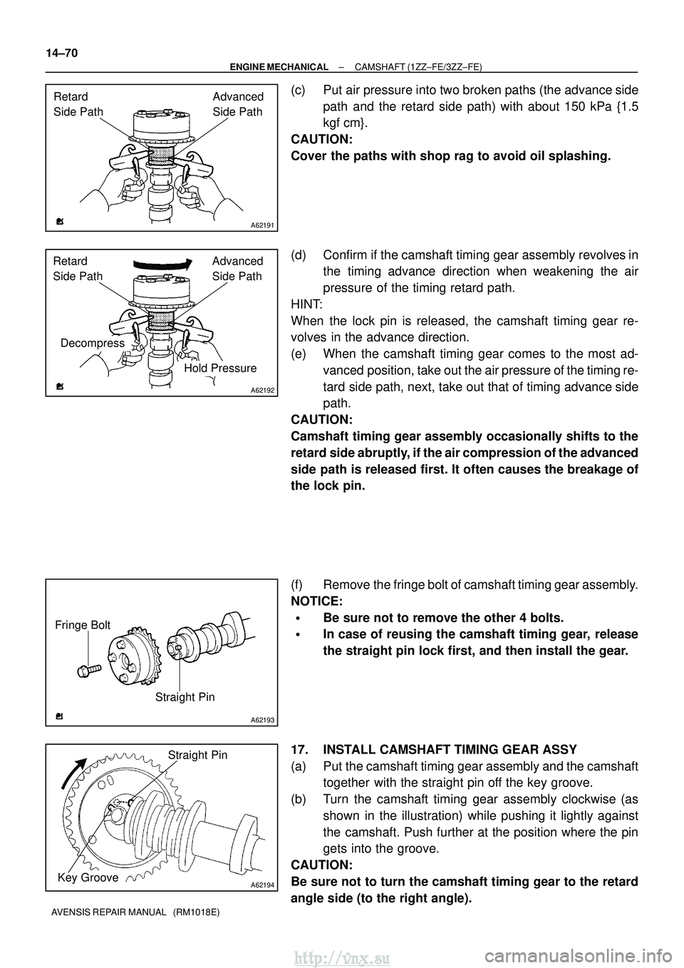
(c) Put air pressure into two broken paths (the advance side path and the retard side path) with about 150 kPa {1.5
kgf�cm}.
CAUTION:
Cover the paths with shop rag to avoid oil splashing.
(d) Confirm if the camshaft timing gear assembly revolves in the timing advance direction when weakening the air
pressure of the timing retard path.
HINT:
When the lock pin is released, the camshaft timing gear re-
volves in the advance direction.
(e) When the camshaft timing gear comes to the most ad- vanced position, take out the air pressure of the timing re-
tard side path, next, take out that of timing advance side
path.
CAUTION:
Camshaft timing gear assembly occasionally shifts to the
retard side abruptly, if the air compression of the advanced
side path is released first. It often causes the breakage of
the lock pin.
(f) Remove the fringe bolt of camshaft timing gear assembly.
NOTICE:
�Be sure not to remove the other 4 bolts.
�In case of reusing the camshaft timing gear, release
the straight pin lock first, and then install the gear.
17. INSTALL CAMSHAFT TIMING GEAR ASSY
(a) Put the camshaft timing gear assembly and the camshaft together with the straight pin off the key groove.
(b) Turn the camshaft timing gear assembly clockwise (as shown in the illustration) while pushing it lightly against
the camshaft. Push further at the position where the pin
gets into the groove.
CAUTION:
Be sure not to turn the camshaft timing gear to the retard
angle side (to the right angle).
http://vnx.su
Page 491 of 2234

A62178
Push
A62180
DisconnectHook
PinTurn
A62181
Plunger
Turn
Push
A11858
A64005
±
ENGINE MECHANICALCAMSHAFT(1ZZ±FE/3ZZ±FE)
14±73
AVENSIS REPAIR MANUAL (RM1018E)
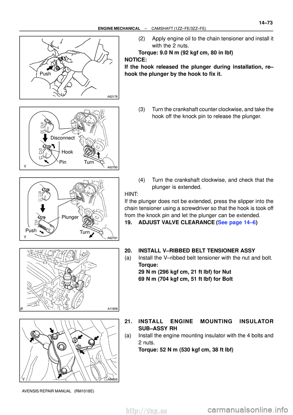
(2)Apply engine oil to the chain tensioner and install it
with the 2 nuts.
Torque: 9.0 N �m (92 kgf�cm, 80 in�lbf)
NOTICE:
If the hook released the plunger during installation, re±
hook the plunger by the hook to fix it.
(3)Turn the crankshaft counter clockwise, and take thehook off the knock pin to release the plunger.
(4)Turn the crankshaft clockwise, and check that the plunger is extended.
HINT:
If the plunger does not be extended, press the slipper into the
chain tensioner using a screwdriver so that the hook is took off
from the knock pin and let the plunger can be extended.
19.ADJUST VALVE CLEARANCE(See page 14±6)
20. INSTALL V±RIBBED BELT TENSIONER ASSY
(a) Install the V±ribbed belt tensioner with the nut and bolt. Torque:
29 N�m (296 kgf� cm, 21 ft�lbf) for Nut
69 N� m (704 kgf� cm, 51 ft�lbf) for Bolt
21. INSTALL ENGINE MOUNTING INSULATOR SUB±ASSY RH
(a) Install the engine mounting insulator with the 4 bolts and
2 nuts.
Torque: 52 N �m (530 kgf� cm, 38 ft�lbf)
http://vnx.su
Page 504 of 2234
A77382
Groove90
�
A77383
Groove
A66833
B11424
±
ENGINE MECHANICAL CHAIN SUB±ASSY (1AZ±FE)
14±145
AVENSIS REPAIR MANUAL (RM1018E)
37. REMOVE NO.2 CHAIN SUB±ASSY
(a) Turn the crankshaft counterclockwise 90 �, and align an
adjusting hole of the oil pump drive shaft gear with the
groove of the oil pump.
(b) Put a 4 mm diameter bar in the adjusting hole of the oil pump drive shaft gear to lock in position, and remove the
nut.
(c) Remove the bolt, and then remove the chain tensioner and spring.
(d) Remove the oil pump drive shaft gear and chain No. 2.
38. INSTALL NO.2 CHAIN SUB±ASSY
(a) Set the crankshaft key to the left side position.
(b) Orient the flat portion of the drive shaft upward.
http://vnx.su
Page 505 of 2234
A77384
Mark Link
Timing Mark
Timing Mark
Mark Link
A77385
Groove
A77386
Groove
A77387
90 �
14±146
±
ENGINE MECHANICAL CHAIN SUB±ASSY (1AZ±FE)
AVENSIS REPAIR MANUAL (RM1018E)
(c) Align the mark links (yellow colored links) with the timing marks of each gear as shown in the illustration.
(d) Install the gears to the crankshaft and oil pump shaft with
the chain wrapped.
(e) Temporarily tighten the oil pump drive shaft gear with the nut.
(f) Insert the damper spring into the adjusting hole, and install the chain tensioner plate with the bolt.
Torque: 12 N �m (122 kgf� cm, 9.0 ft�lbf)
(g) Align an adjusting hole of the sprocket with the groove of the oil pump.
(h) Insert a 4 mm diameter bar into the adjusting hole of the sprocket to lock in position, and tighten the nut.
Torque: 30 N �m (301 kgf� cm, 22 ft�lbf)
(i) Rotate the crankshaft clockwise 90� , and position the
crankshaft key upward.
http://vnx.su
Page 510 of 2234
A77395
Engine
Front
A77396
Hook
PinTurn
Disconnect
A77397
Push Turn
Plunger
A77398
A
B
A
A
±
ENGINE MECHANICAL CHAIN SUB±ASSY (1AZ±FE)
14±151
AVENSIS REPAIR MANUAL (RM1018E)
(b) Install a new gasket chain tensioner with the 2 nuts.
Torque: 9.0 N �m (92 kgf �cm, 80 in. �lbf)
NOTICE:
If the hook is released wile inserting, apply the hook again,
and insert the chain tensioner.
(c) Turn the crankshaft counterclockwise, and check that the
hook is disengaged from the plunger knock pin.
(d) Turn the crankshaft clockwise, and check that the plunger is extended.
52. INSTALL TRANSVERSE ENGINE ENGINE MOUNTING INSULATOR Torque: 52 N �m (530 kgf� cm, 38 ft�lbf)
53. INSTALL ENGINE MOUNTING BRACKET NO.2 RH Torque:
A 52 N� m (530 kgf� cm, 38 ft�lbf)
B 113 N� m (1,152 kgf �cm, 83 ft �lbf)
54. INSTALL CYLINDER HEAD COVER SUB±ASSY
(a) Remove any old seal packing (FIPG) material.
http://vnx.su
Page 518 of 2234
A77382
Groove90
�
A77383
Groove
A66833
B11424
±
ENGINE MECHANICAL CHAIN SUB±ASSY (1AZ±FE)
14±145
AVENSIS REPAIR MANUAL (RM1018E)
37. REMOVE NO.2 CHAIN SUB±ASSY
(a) Turn the crankshaft counterclockwise 90 �, and align an
adjusting hole of the oil pump drive shaft gear with the
groove of the oil pump.
(b) Put a 4 mm diameter bar in the adjusting hole of the oil pump drive shaft gear to lock in position, and remove the
nut.
(c) Remove the bolt, and then remove the chain tensioner and spring.
(d) Remove the oil pump drive shaft gear and chain No. 2.
38. INSTALL NO.2 CHAIN SUB±ASSY
(a) Set the crankshaft key to the left side position.
(b) Orient the flat portion of the drive shaft upward.
http://vnx.su