Page 284 of 2234
A60620
Close
Open
Valve
VaIve
Open
Close
Valve
1ZZ±FE:
3ZZ±FE: VaIve
10±2
±
ENGINE CONTROL SYSTEM SFI SYSTEM (1ZZ±FE/3ZZ±FE)
AVENSIS REPAIR MANUAL (RM1018E)
3. INSPECT IDLE AIR CONTROL VALVE
NOTICE:
�It is impossible to check the resister value and the op-
eration of ISCV by itself, because the ISCV has an IC
circuit inside it, which transforms the duty signal
from the ECM to the derive signal.
�Clear the DTC after inspection.
HINT:
When the ISCV system has malfunctions except for its adher-
ence, DTC P0505 is detected.
(a) Operation inspection. (1) Connect the ISCV connector to the ISCV.
(2) Check the valve movement when the ignition switch
is turned ON.
Movement:
Half open �fully close � fully open � half open
HINT:
ISCV moves within 0.5 second.
http://vnx.su
Page 290 of 2234
A77879
45�
A77880
83.8 mm
(3.299 in.)
Rotation
Center of
Throttle Link
±
ENGINE CONTROL SYSTEMTHROTTLE BODY ASSY(1AZ±FE)
10±29
AVENSIS REPAIR MANUAL (RM1018E)
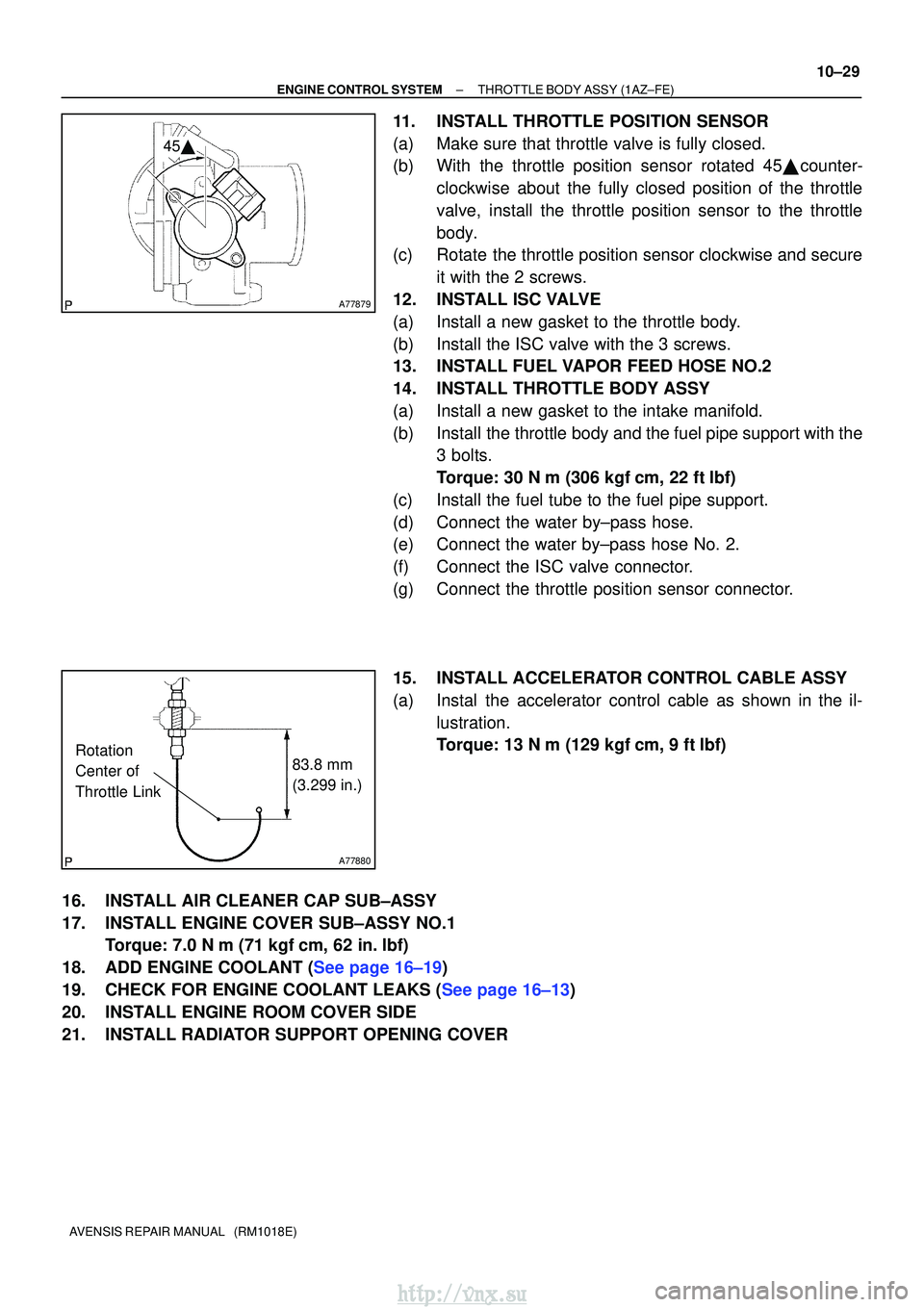
11.INSTALL THROTTLE POSITION SENSOR
(a)Make sure that throttle valve is fully closed.
(b)With the throttle position sensor rotated 45� counter-
clockwise about the fully closed position of the throttle
valve, install the throttle position sensor to the throttle
body.
(c)Rotate the throttle position sensor clockwise and secure
it with the 2 screws.
12.INSTALL ISC VALVE
(a)Install a new gasket to the throttle body.
(b)Install the ISC valve with the 3 screws.
13.INSTALL FUEL VAPOR FEED HOSE NO.2
14.INSTALL THROTTLE BODY ASSY
(a)Install a new gasket to the intake manifold.
(b)Install the throttle body and the fuel pipe support with the 3 bolts.
Torque: 30 N �m (306 kgf�cm, 22 ft�lbf)
(c)Install the fuel tube to the fuel pipe support.
(d)Connect the water by±pass hose.
(e)Connect the water by±pass hose No. 2.
(f)Connect the ISC valve connector.
(g)Connect the throttle position sensor connector.
15.INSTALL ACCELERATOR CONTROL CABLE ASSY
(a)Instal the accelerator control cable as shown in the il- lustration.
Torque: 13 N�m (129 kgf�cm, 9 ft�lbf)
16.INSTALL AIR CLEANER CAP SUB±ASSY
17.INSTALL ENGINE COVER SUB±ASSY NO.1 Torque: 7.0 N �m (71 kgf�cm, 62 in. �lbf)
18.ADD ENGINE COOLANT (See page 16±19)
19.CHECK FOR ENGINE COOLANT LEAKS (See page 16±13)
20. INSTALL ENGINE ROOM COVER SIDE
21. INSTALL RADIATOR SUPPORT OPENING COVER
http://vnx.su
Page 294 of 2234
A78511
(b)
A78512
(d)
A78513
(g)
(h)
±
ENGINE CONTROL SYSTEMTHROTTLE BODY ASSY(1AZ±FSE)
10±45
AVENSIS REPAIR MANUAL (RM1018E)
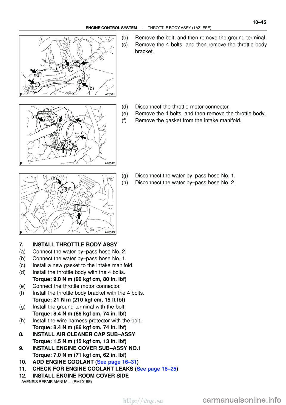
(b)Remove the bolt, and then remove the ground terminal.
(c)Remove the 4 bolts, and then remove the throttle body
bracket.
(d)Disconnect the throttle motor connector.
(e)Remove the 4 bolts, and then remove the throttle body.
(f)Remove the gasket from the intake manifold.
(g)Disconnect the water by±pass hose No. 1.
(h)Disconnect the water by±pass hose No. 2.
7.INSTALL THROTTLE BODY ASSY
(a)Connect the water by±pass hose No. 2.
(b)Connect the water by±pass hose No. 1.
(c)Install a new gasket to the intake manifold.
(d)Install the throttle body with the 4 bolts. Torque: 9.0 N �m (90 kgf�cm, 80 in. �lbf)
(e)Connect the throttle motor connector.
(f)Install the throttle body bracket with the 4 bolts. Torque: 21 N �m (210 kgf�cm, 15 ft�lbf)
(g)Install the ground terminal with the bolt. Torque: 8.4 N �m (86 kgf�cm, 74 in. �lbf)
(h)Install the wire harness protector with the bolt. Torque: 8.4 N �m (86 kgf�cm, 74 in. �lbf)
8.INSTALL AIR CLEANER CAP SUB±ASSY Torque: 1.5 N �m (15 kgf�cm, 13 in. �lbf)
9.INSTALL ENGINE COVER SUB±ASSY NO.1 Torque: 7.0 N �m (71 kgf�cm, 62 in. �lbf)
10.ADD ENGINE COOLANT (See page 16±31)
11.CHECK FOR ENGINE COOLANT LEAKS (See page 16±25)
12. INSTALL ENGINE ROOM COVER SIDE
http://vnx.su
Page 301 of 2234
A78463
A
A
A
A
BB
A
(d)
(c)
A78468
65.1 mm
(2.563 in.)
Rotation
Center of
Throttle Link
18�
10±12
±
ENGINE CONTROL SYSTEMTHROTTLE BODY ASSY(1ZZ±FE)
AVENSIS REPAIR MANUAL (RM1018E)
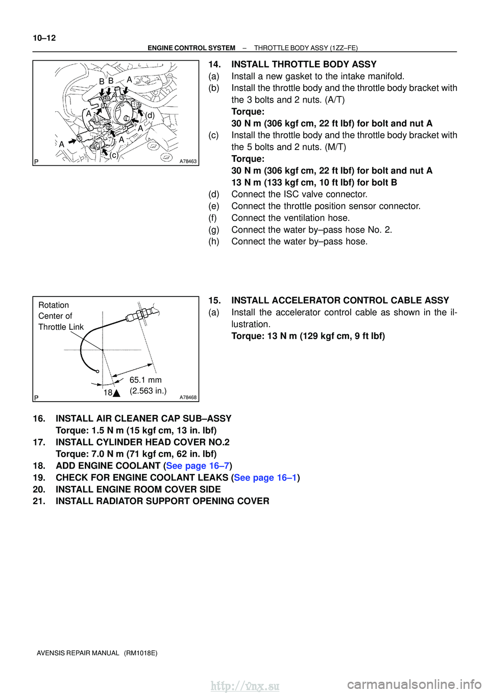
14.INSTALL THROTTLE BODY ASSY
(a)Install a new gasket to the intake manifold.
(b)Install the throttle body and the throttle body bracket with the 3 bolts and 2 nuts. (A/T)
Torque:
30 N�m (306 kgf�cm, 22 ft�lbf) for bolt and nut A
(c)Install the throttle body and the throttle body bracket with
the 5 bolts and 2 nuts. (M/T)
Torque:
30 N�m (306 kgf�cm, 22 ft�lbf) for bolt and nut A
13 N�m (133 kgf�cm, 10 ft�lbf) for bolt B
(d)Connect the ISC valve connector.
(e)Connect the throttle position sensor connector.
(f)Connect the ventilation hose.
(g)Connect the water by±pass hose No. 2.
(h)Connect the water by±pass hose.
15.INSTALL ACCELERATOR CONTROL CABLE ASSY
(a)Install the accelerator control cable as shown in the il-
lustration.
Torque: 13 N�m (129 kgf�cm, 9 ft�lbf)
16.INSTALL AIR CLEANER CAP SUB±ASSY Torque: 1.5 N �m (15 kgf�cm, 13 in. �lbf)
17.INSTALL CYLINDER HEAD COVER NO.2 Torque: 7.0 N �m (71 kgf�cm, 62 in. �lbf)
18.ADD ENGINE COOLANT (See page 16±7)
19.CHECK FOR ENGINE COOLANT LEAKS (See page 16±1)
20. INSTALL ENGINE ROOM COVER SIDE
21. INSTALL RADIATOR SUPPORT OPENING COVER
http://vnx.su
Page 305 of 2234
A78501
A78503
30� to 45�
A78469
66.3 mm
(2.610 in.)
Rotation
Center of
Throttle Link
11�
10±16
±
ENGINE CONTROL SYSTEMTHROTTLE BODY ASSY(3ZZ±FE)
AVENSIS REPAIR MANUAL (RM1018E)
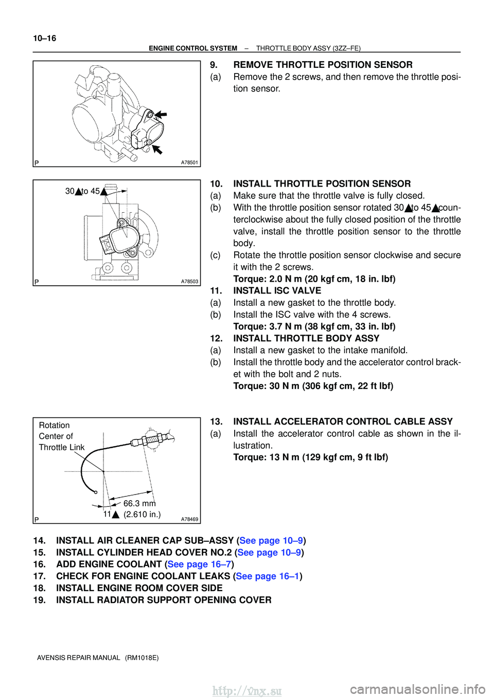
9.REMOVE THROTTLE POSITION SENSOR
(a)Remove the 2 screws, and then remove the throttle posi- tion sensor.
10.INSTALL THROTTLE POSITION SENSOR
(a)Make sure that the throttle valve is fully closed.
(b)With the throttle position sensor rotated 30� to 45� coun- terclockwise about the fully closed position of the throttle
valve, install the throttle position sensor to the throttle
body.
(c)Rotate the throttle position sensor clockwise and secure it with the 2 screws.
Torque: 2.0 N �m (20 kgf�cm, 18 in. �lbf)
11.INSTALL ISC VALVE
(a)Install a new gasket to the throttle body.
(b)Install the ISC valve with the 4 screws.
Torque: 3.7 N �m (38 kgf�cm, 33 in. �lbf)
12.INSTALL THROTTLE BODY ASSY
(a)Install a new gasket to the intake manifold.
(b)Install the throttle body and the accelerator control brack- et with the bolt and 2 nuts.
Torque: 30 N �m (306 kgf�cm, 22 ft�lbf)
13.INSTALL ACCELERATOR CONTROL CABLE ASSY
(a)Install the accelerator control cable as shown in the il- lustration.
Torque: 13 N�m (129 kgf�cm, 9 ft�lbf)
14.INSTALL AIR CLEANER CAP SUB±ASSY (See page 10±9)
15.INSTALL CYLINDER HEAD COVER NO.2 (See page 10±9)
16.ADD ENGINE COOLANT (See page 16±7)
17.CHECK FOR ENGINE COOLANT LEAKS (See page 16±1)
18. INSTALL ENGINE ROOM COVER SIDE
19. INSTALL RADIATOR SUPPORT OPENING COVER
http://vnx.su
Page 311 of 2234
A79149
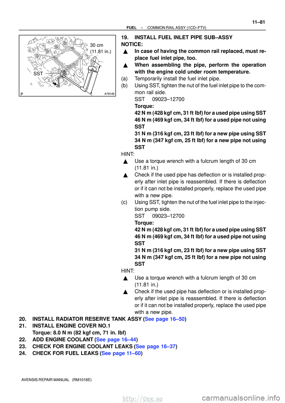
30 cm
(11.81 in.)
SST
±
FUELCOMMON RAIL ASSY(1CD±FTV)
11±81
AVENSIS REPAIR MANUAL (RM1018E)
19.INSTALL FUEL INLET PIPE SUB±ASSY
NOTICE:
�In case of having the common rail replaced, must re-
place fuel inlet pipe, too.
�When assembling the pipe, perform the operation
with the engine cold under room temperature.
(a)Temporarily install the fuel inlet pipe.
(b)Using SST, tighten the nut of the fuel inlet pipe to the com-
mon rail side.
SST09023±12700
Torque:
42 N�m (428 kgf�cm, 31 ft�lbf) for a used pipe using SST
46 N�m (469 kgf�cm, 34 ft�lbf) for a used pipe not using
SST
31 N �m (316 kgf�cm, 23 ft�lbf) for a new pipe using SST
34 N�m (347 kgf �cm, 25 ft�lbf) for a new pipe not using
SST
HINT:
�Use a torque wrench with a fulcrum length of 30 cm
(11.81 in.)
�Check if the used pipe has deflection or is installed prop-
erly after inlet pipe is reassembled. If there is deflection
or if it can not be installed properly, replace the used pipe
with a new pipe.
(c)Using SST, tighten the nut of the fuel inlet pipe to the injec-
tion pump side.
SST09023±12700
Torque:
42 N�m (428 kgf�cm, 31 ft�lbf) for a used pipe using SST
46 N�m (469 kgf�cm, 34 ft�lbf) for a used pipe not using
SST
31 N �m (316 kgf�cm, 23 ft�lbf) for a new pipe using SST
34 N�m (347 kgf �cm, 25 ft�lbf) for a new pipe not using
SST
HINT:
�Use a torque wrench with a fulcrum length of 30 cm
(11.81 in.)
�Check if the used pipe has deflection or is installed prop-
erly after inlet pipe is reassembled. If there is deflection
or if it can not be installed properly, replace the used pipe
with a new pipe.
20.INSTALL RADIATOR RESERVE TANK ASSY(See page 16±50)
21. INSTALL ENGINE COVER NO.1 Torque: 8.0 N �m (82 kgf �cm, 71 in. �lbf)
22.ADD ENGINE COOLANT(See page 16±44)
23.CHECK FOR ENGINE COOLANT LEAKS(See page 16±37)
24.CHECK FOR FUEL LEAKS(See page 11±60)
http://vnx.su
Page 316 of 2234
110U1±01
A77908
Retainer
(at 4 places)
Insert
SST
Turn
Fuel Pipe
Clamp
A76220
O±ring
Nylon Tube HousingPipe
Retainer
A77909
11±26
±
FUELFUEL INJECTOR ASSY(1AZ±FE)
AVENSIS REPAIR MANUAL (RM1018E)
REPLACEMENT
1.DISCHARGE FUEL SYSTEM PRESSURE (See page 11±15)
2.REMOVE ENGINE COVER SUB±ASSY NO.1 (See page 10±26)
3.REMOVE AIR CLEANER CAP SUB±ASSY (See page 10±26) 4. DISCONNECT FUEL TUBE SUB±ASSY
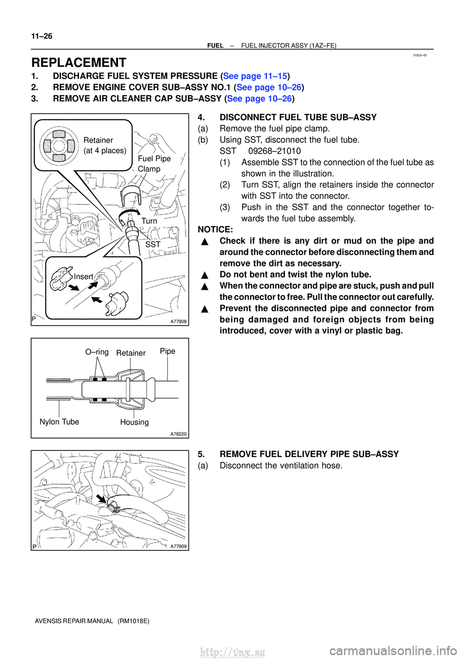
(a) Remove the fuel pipe clamp.
(b) Using SST, disconnect the fuel tube.SST 09268±21010
(1) Assemble SST to the connection of the fuel tube asshown in the illustration.
(2) Turn SST, align the retainers inside the connector
with SST into the connector.
(3) Push in the SST and the connector together to- wards the fuel tube assembly.
NOTICE:
�Check if there is any dirt or mud on the pipe and
around the connector before disconnecting them and
remove the dirt as necessary.
�Do not bent and twist the nylon tube.
�When the connector and pipe are stuck, push and pull
the connector to free. Pull the connector out carefully.
�Prevent the disconnected pipe and connector from
being damaged and foreign objects from being
introduced, cover with a vinyl or plastic bag.
5. REMOVE FUEL DELIVERY PIPE SUB±ASSY
(a) Disconnect the ventilation hose.
http://vnx.su
Page 318 of 2234
A77913
Turn
Push
A77914
Turn
A81621
Fuel Pipe
Clamp
Push
11±28
±
FUELFUEL INJECTOR ASSY(1AZ±FE)
AVENSIS REPAIR MANUAL (RM1018E)
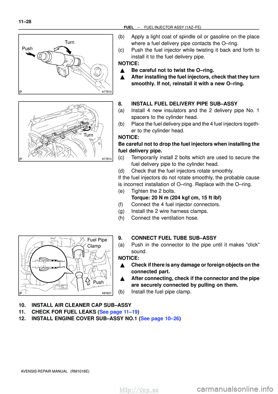
(b)Apply a light coat of spindle oil or gasoline on the place where a fuel delivery pipe contacts the O±ring.
(c)Push the fuel injector while twisting it back and forth to
install it to the fuel delivery pipe.
NOTICE:
�Be careful not to twist the O±ring.
�After installing the fuel injectors, check that they turn
smoothly. If not, reinstall it with a new O±ring.
8.INSTALL FUEL DELIVERY PIPE SUB±ASSY
(a)Install 4 new insulators and the 2 delivery pipe No. 1 spacers to the cylinder head.
(b)Place the fuel delivery pipe and the 4 fuel injectors togeth- er to the cylinder head.
NOTICE:
Be careful not to drop the fuel injectors when installing the
fuel delivery pipe.
(c)Temporarily install 2 bolts which are used to secure the fuel delivery pipe to the cylinder head.
(d)Check that the fuel injectors rotate smoothly.
If the fuel injectors do not rotate smoothly, the probable cause
is incorrect installation of O±ring. Replace with the O±ring.
(e)Tighten the 2 bolts. Torque: 20 N �m (204 kgf�cm, 15 ft�lbf)
(f)Connect the 4 fuel injector connectors.
(g)Install the 2 wire harness clamps.
(h)Connect the ventilation hose.
9.CONNECT FUEL TUBE SUB±ASSY
(a)Push in the connector to the pipe until it makes ºclickº sound.
NOTICE:
�Check if there is any damage or foreign objects on the
connected part.
�After connecting, check if the connector and the pipe
are securely connected by pulling on them.
(b)Install the fuel pipe clamp.
10.INSTALL AIR CLEANER CAP SUB±ASSY
11.CHECK FOR FUEL LEAKS (See page 11±19)
12.INSTALL ENGINE COVER SUB±ASSY NO.1 (See page 10±26)
http://vnx.su