Page 67 of 2234

010B2±13
N17080
Filler Cap
Float
Reservoir Tank� Grommet
Clip
Slotted Spring Pin
: Specified torque
� Non±reusable part Cylinder
Piston
Push Rod
Washer
Snap Ring
Boot
�
Gasket
Lock Nut
Clevis Pin
Clevis
N´m (kgf´cm, ft´lbf)
12 (120, 9)
15 (155, 11)
±
INTRODUCTION HOW TO USE THIS MANUAL
01±1
AVENSIS REPAIR MANUAL (RM1018E)
HOW TO USE THIS MANUAL
GENERAL INFORMATION
1. GENERAL DESCRIPTION
(a) This manual is made in accordance with SAE J2008.
(b) Generally, repair operations can be separated in the following 3 main processes:
1. Diagnosis
2. Removing/Installing, Replacing, Disassembling/Reassembling, Checking \
and Adjusting
3. Final Inspection
(c) This manual explains the 1st process of ºDiagnosisº (found in the ºDiagnosticsº section), the 2nd
pro-
cess of ºRemoving and Installing, Replacing, Disassembling, Installing and Ch\
ecking, and Adjustingº,
but the 3rd process of ºFinal Inspectionº is omitted.
(d) The following essential operations are not written in this manual. However, these operations must be performed in actual situations.
(1) Operations with a jack or lift
(2) Cleaning of a removed part when necessary
(3) Visual check
2. INDEX
(a) An alphabetical INDEX section is provided at the end of the book as a refe\
rence to help you find the item to be repaired.
3. PREPARATION
(a) Use of special service tools (SST) and special service materials (SSM\
) may be required, depending
on the repair situation. Be sure to use SST and SSM when they are requir\
ed and follow the working
procedure properly. A list of SST and SSM is in the Preparation section of this manual.
4. REPAIR PROCEDURES
(a) Component drawing is placed under the title where necessary.
(b) Non±reusable parts, grease application area, precoated parts and tigh\
tening torque are specified in the component drawings.
Example:
http://vnx.su
Page 100 of 2234
022KS±01
±
PREPARATION BRAKE
02±33
AVENSIS REPAIR MANUAL (RM1018E)
BRAKE
PREPARATION
SST
09023±00100Union Nut Wrench 10 mmBRAKE FLUID
BRAKE MASTER CYLINDER
SUB±ASSY
FRONT BRAKE
REAR BRAKE
BRAKE BOOSTER ASSY(LHD)
BRAKE BOOSTER ASSY(RHD)
BRAKE ACTUATOR ASSY(W/ VSC)
BRAKE ACTUATOR ASSY(W/O VSC)
09023±38400Union Nut Wrench 14mmBRAKE FLUID
BRAKE MASTER CYLINDER
SUB±ASSY
FRONT BRAKE
REAR BRAKE
BRAKE BOOSTER ASSY(LHD)
BRAKE BOOSTER ASSY(RHD)
BRAKE ACTUATOR ASSY(W/ VSC)
09214±76011Crankshaft Pulley ReplacerSKID CONTROL SENSOR
09520±00031Rear Axle Shaft PullerSKID CONTROL SENSOR
(09520±00040)ShockerSKID CONTROL SENSOR
09521±00020Drive Shaft Boot Clamping ToolSKID CONTROL SENSOR
09550±60010Differential Side Bearing
ReplacerFRONT BRAKE
(09710±06051)ReplacerREAR BRAKE
09950±00020Bearing RemoverSKID CONTROL SENSOR
Recomended Tools
09042±00010Torx Socket T30STEERING SENSOR
http://vnx.su
Page 1009 of 2234

FRONT WHEEL ALIGNMENT
ADJUSTMENT
1.INSPECT TIRE")
2600L±02
F44617
Front:AB
F44618
Rear:
C D
SA3213
A
D B
Front
C
F44619
26±6
±
FRONT SUSPENSION FRONT WHEEL ALIGNMENT
AVENSIS REPAIR MANUAL (RM1018E)
FRONT WHEEL ALIGNMENT
ADJUSTMENT
1.INSPECT TIRE (See page 28±1) 2. MEASURE VEHICLE HEIGHT
Vehicle height:
(Normal package)
FrontA ± B: 92 mm (3.62 in.)
RearD ± C: 61 mm (2.40 in.)
(Rough road package)
FrontA ± B: 72 mm (2.83 in.)
RearD ± C: 41 mm (1.61 in.)
Measuring points:
A: Ground clearance of front wheel center
B: Ground clearance of lower suspension arm front bolt
center
C: Ground clearance of toe control arm inner bolt center
D: Ground clearance of rear wheel center
NOTICE:
Before inspecting the wheel alignment, adjust the vehicle
height to the specified value.
If the vehicle height is not the specified value, adjust it by push-
ing down or lifting the body.
3. INSPECT TOE±IN
Toe±in:
Toe±in(total)A + B: 0� 06' � 12' (0.1 � � 0.2� )
C ± D: 1 � 2 mm (0.04 � 0.08 in.)
If the toe±in is not within the specified value, adjust it at the rack
ends.
4. ADJUST TOE±IN
(a) Remove the rack boot set clips.
(b) Loosen the tie rod end lock nuts.
(c) Turn the right and left rack ends by an equal amount to
adjust the toe±in.
HINT:
Adjust the toe±in to the center of the specified value as much
as possible.
(d) Make sure that the lengths of the right and left rack ends are the same.
(e) Torque the tie rod end lock nuts.
Torque: 74 N´m (755 kgf´cm, 55 ft´lbf)
(f) Place the boots on the seats and install the clips.
HINT:
Make sure that the boots are not twisted.
http://vnx.su
Page 1054 of 2234
F40217
SSTTurn
Hold
C80293
D27403
C83023
±
DRIVE SHAFT / PROPELLER SHAFT FRONT AXLE HUB SUB±ASSY LH
30±23
AVENSIS REPAIR MANUAL (RM1018E)
6. REMOVE FRONT DISC
7. SEPARATE TIE ROD END SUB±ASSY LH
(a) Remove the cotter pin and nut.
(b) Using SST, separate the tie rod end sub±assy LH from thesteering knuckle.
SST 09628±62011
8. SEPARATE FRONT SUSPENSION ARM SUB±ASSY LOWER NO.1 LH
(a) Remove the bolt and 2 nuts, and separate the suspension arm sub±assy lower No.1 LH from the lower ball joint.
9. REMOVE FRONT AXLE ASSY LH
(a) Using a plastic hammer, separate the drive shaft assy LH from the axle hub.
NOTICE:
Be careful not to damage the boot and ABS speed sensor
rotor.
(b) Remove the 2 bolts, nuts and steering knuckle with the
shock absorber.
http://vnx.su
Page 1057 of 2234

19.INSTALL LOWER BALL JOINT ASSY FRONT LH
(a)Install the lower ball joint and torque")
C83023
C80293
30±26
±
DRIVE SHAFT / PROPELLER SHAFTFRONT AXLE HUB SUB±ASSY LH
AVENSIS REPAIR MANUAL (RM1018E)
19.INSTALL LOWER BALL JOINT ASSY FRONT LH
(a)Install the lower ball joint and torque the nut. Torque: 103 N�m (1,050 kgf�cm, 76 ft�lbf)
(b)Install a new cotter pin.
NOTICE:
If the holes for the cotter pin are not aligned, tighten the nut up to 6\
0� further.
20.INSTALL FRONT AXLE ASSY LH
(a)Install the 2 bolts, nuts and steering knuckle with 2 boltsand nuts to the shock absorber.
Torque: 220 N�m (2,243 kgf�cm, 162 ft�lbf)
NOTICE:
Only when reusing the bolts and nuts, apply engine oil to
the screw part of the nuts.
(b)Push the front axle assy toward the outside of the vehicle, fit the splined part of the drive shaft assy to that of the front
axle assy and insert the drive shaft assy into the front axle
assy.
NOTICE:
�Do not push out the front axle assy excessively.
�Be careful not to damage the drive shaft outboard
joint boot.
�Be careful not to damage the speed sensor rotor.
21.INSTALL FRONT SUSPENSION ARM SUB±ASSY LOWER NO.1 LH
(a)Install the front suspension arm sub±assy lower No.1 LH and lower ball joint with the 2 nuts and bolt.
Torque: 89 N �m (908 kgf�cm, 66 ft�lbf)
22.INSTALL TIE ROD END SUB±ASSY LH
(a)Install the tie rod end sub±assy LH to the steering knuckle.
(b)Install the nut and a new cotter pin. Torque: 49 N �m (500 kgf�cm, 36 ft�lbf)
NOTICE:
If the holes for the cotter pin are not aligned, tighten the nut up to 6\
0� further.
23.INSTALL FRONT STABILIZER LINK ASSY LH (See page 30±6)
24. INSTALL FRONT DISC
http://vnx.su
Page 1062 of 2234
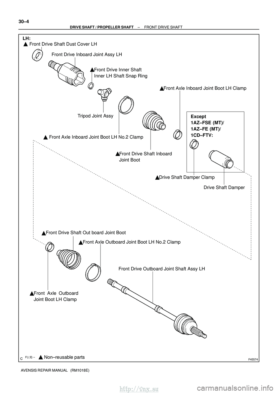
������F45574Non±reusable parts
� �
Front Drive Shaft Dust Cover LH
Front Drive Inboard Joint Assy LH
Front Drive Inner Shaft
Inner LH Shaft Snap Ring Front Axle Inboard Joint Boot LH Clamp
Drive Shaft Damper
Drive Shaft Damper Clamp
Front Drive Shaft Inboard
Joint Boot
Front Axle Inboard Joint Boot LH No.2 Clamp
Tripod Joint Assy
�
� ��
�
Front Drive Shaft Out board Joint Boot
Front Axle Outboard Joint Boot LH No.2 Clamp
�
Front Drive Outboard Joint Shaft Assy LH
Front Axle Outboard
Joint Boot LH Clamp
LH:
Except
1AZ±FSE (MT)/
1AZ±FE (MT)/
1CD±FTV:
�
�
30±4
±
DRIVE SHAFT / PROPELLER SHAFT FRONT DRIVE SHAFT
AVENSIS REPAIR MANUAL (RM1018E)
http://vnx.su
Page 1063 of 2234
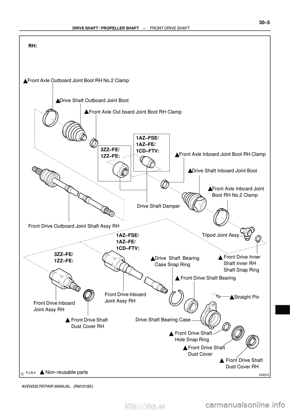
������F45575Non±reusable parts
�
Front Axle Outboard Joint Boot RH No.2 Clamp
Drive Shaft Outboard Joint BootFront Axle Out board Joint Boot RH Clamp
Drive Shaft DamperFront Axle Inboard Joint Boot RH Clamp
Drive Shaft Inboard Joint Boot
Front Axle Inboard Joint
Boot RH No.2 Clamp
�
�
Front Drive Outboard Joint Shaft Assy RH
RH:
3ZZ±FE/
1ZZ±FE: 1AZ±FSE/
1AZ±FE/
1CD±FTV:
Front Drive Inboard
Joint Assy RH
Front Drive Shaft
Dust Cover RH Tripod Joint Assy
Front Drive Inner
Shaft Inner RH
Shaft Snap Ring
Drive Shaft Bearing
Case Snap Ring
Front Drive Shaft Bearing
Straight Pin
Drive Shaft Bearing Case Front Drive Shaft
Hole Snap RingFront Drive Shaft
Dust Cover Front Drive Shaft
Dust Cover RH
�
� �
�
� �
�
�
3ZZ±FE/
1ZZ±FE:
1AZ±FSE/
1AZ±FE/
1CD±FTV:
Front Drive Inboard
Joint Assy RH �
�
��
±
DRIVE SHAFT / PROPELLER SHAFT FRONT DRIVE SHAFT
30±5
AVENSIS REPAIR MANUAL (RM1018E)
http://vnx.su
Page 1107 of 2234
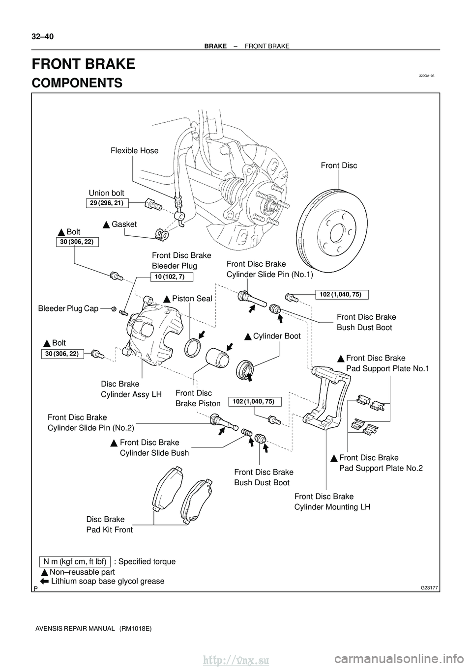
320GA±03
G23177
Disc Brake
Cylinder Assy LH�
GasketFlexible Hose
Disc Brake
Pad Kit Front
Front Disc Brake
Pad Support Plate No.1
Front Disc Brake
Cylinder Slide Pin (No.2)
Front Disc Brake
Bush Dust Boot
Front Disc Brake
Cylinder Slide Pin (No.1)
Front Disc Brake
Cylinder Slide Bush Front Disc Brake
Cylinder Mounting LH
� Cylinder Boot
�
Piston Seal
Front Disc
Brake Piston Front Disc
30 (306, 22)
102 (1,040, 75)
30 (306, 22)
Bleeder Plug Cap
Front Disc Brake
Bleeder Plug
�
Non±reusable part
N�m (kgf� cm, ft�lbf) : Specified torque
Lithium soap base glycol grease
29 (296, 21)
10 (102, 7)
Union bolt
Front Disc Brake
Pad Support Plate No.2
102 (1,040, 75)
� Front Disc Brake
Bush Dust Boot
�
Bolt
� Bolt
�
�
32±40
±
BRAKE FRONT BRAKE
AVENSIS REPAIR MANUAL (RM1018E)
FRONT BRAKE
COMPONENTS
http://vnx.su

BRAKE
PREPARATION
SST
09023±00100Union Nut Wrench 10 mmBRAKE FLUID
BRAKE MASTER CYLINDER
SUB±ASSY
FRONT BRAKE
REAR BRAKE
BRAK")

6. REMOVE FRONT DISC
7. SEPARATE TIE ROD END SUB±ASSY LH")