Page 1209 of 2234

(1)
(1) (1)
(2)
(2)
±
CLUTCH CLUTCH RELEASE CYLINDER ASSY (MTM)
42±19
AVENSIS REPAIR MANUAL (RM1018E)
10. INSTA")
CL0672
D26804
D30488
1ZZ±FE/3ZZ±FE Engine Type:
1AZ±FE/1AZ±FSE Engine Type:(1)
(1)
(1) (1)
(2)
(2)
±
CLUTCH CLUTCH RELEASE CYLINDER ASSY (MTM)
42±19
AVENSIS REPAIR MANUAL (RM1018E)
10. INSTALL CLUTCH RELEASE CYLINDER KIT
(a) Install the bleeder plug cap to the bleeder plug.
(b) Install a new spring to the cylinder body.
(c) Coat the parts with lithium soap base glycol grease, as
shown in the illustration.
(d) Install the piston to the cylinder body.
NOTICE:
Be careful not to damage the inside of the cylinder body.
(e) Install the push rod to the cylinder body.
(f) Install the boot to the cylinder body.
11. INSTALL CLUTCH RELEASE CYLINDER ASSY (1CD±FTV ENGINE TYPE)
(a) Using a 12 mm deep socket wrench, install the clutch re- lease cylinder assy with the 2 bolts.
Torque: 12 N �m (120 kgf� cm, 9 ft�lbf)
12. INSTALL CLUTCH RELEASE CYLINDER ASSY (EXCEPT 1CD±FTV ENGINE TYPE)
(a) 1ZZ±FE/3ZZ±FE Engine Type: (1) Install the clutch release cylinder and clutch line
bracket with the 2 bolts.
Torque: 14 N �m (141 kgf� cm, 10 ft�lbf)
(2) Install the flexible hose tube with the bolt.
Torque: 5.0 N �m (51 kgf �cm, 44 in. �lbf)
(b) 1AZ±FE/1AZ±FSE Engine Type:
(1) Install the clutch release cylinder with the 2 bolts.
Torque: 12 N �m (120 kgf� cm, 9 ft�lbf)
(2) Install the flexible hose tube with the bolt.
Torque: 12 N �m (122 kgf� cm, 9 ft�lbf)
http://vnx.su
Page 1212 of 2234
4206H±01
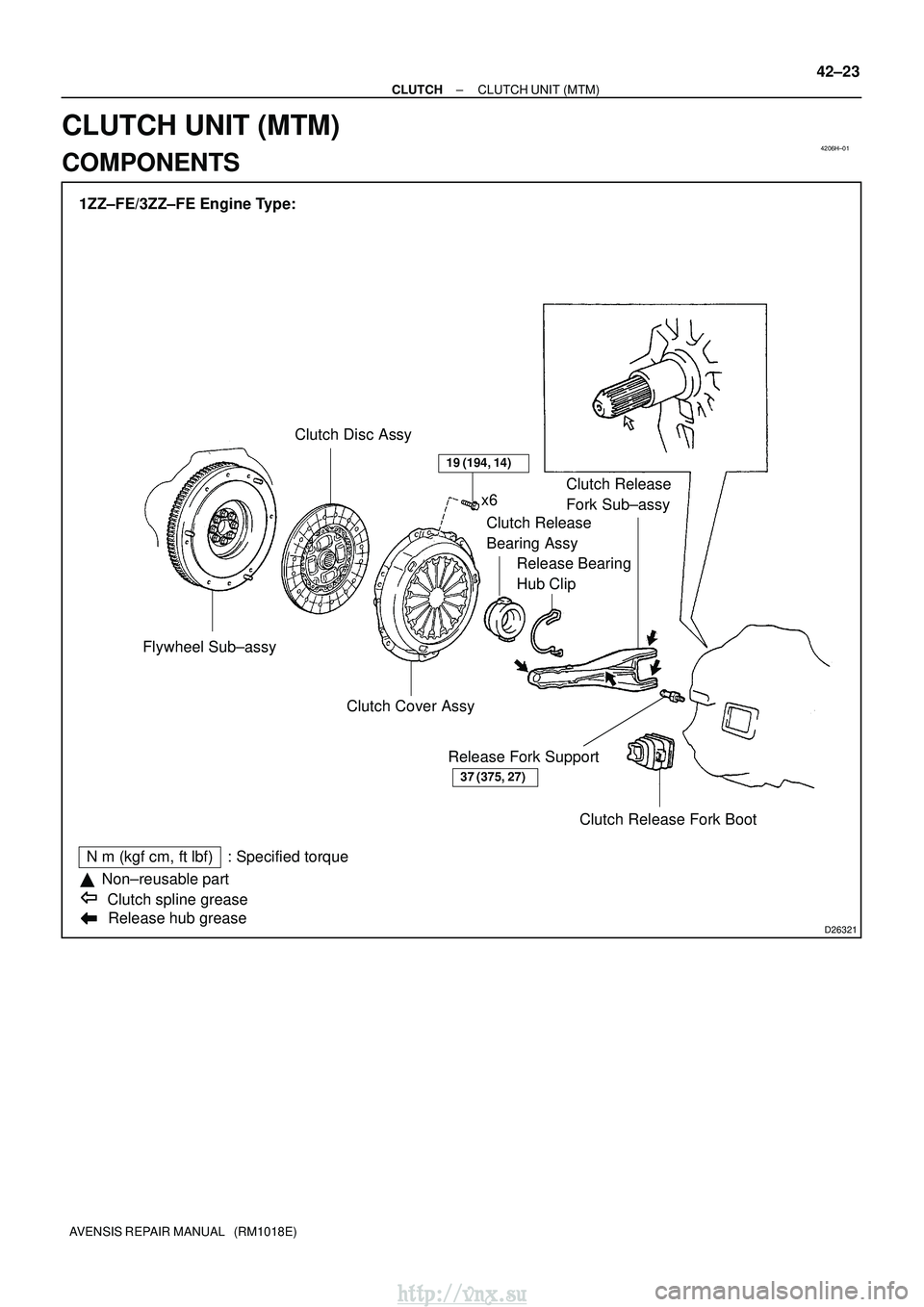
D26321
1ZZ±FE/3ZZ±FE Engine Type:Flywheel Sub±assy Clutch Disc Assy
Release hub grease
N �m (kgf� cm, ft�lbf) : Specified torque
�Non±reusable part
Clutch spline grease x6
Clutch Release
Bearing Assy Release Bearing
Hub Clip Clutch Release
Fork Sub±assy
Clutch Cover Assy Clutch Release Fork Boot
Release Fork Support
37 (375, 27)
19 (194, 14)
±
CLUTCH CLUTCH UNIT (MTM)
42±23
AVENSIS REPAIR MANUAL (RM1018E)
CLUTCH UNIT (MTM)
COMPONENTS
http://vnx.su
Page 1213 of 2234
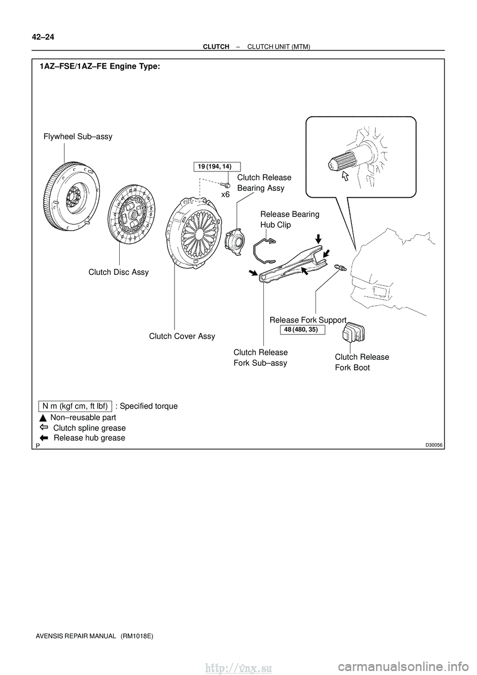
D30056Release hub grease
N�m (kgf� cm, ft�lbf) : Specified torque
�Non±reusable part
Clutch spline grease
1AZ±FSE/1AZ±FE Engine Type:
Flywheel Sub±assy
Clutch Disc Assy Clutch Release
Fork Sub±assy
Clutch Cover Assy Release Bearing
Hub Clip
Clutch Release
Bearing Assy
Release Fork Support Clutch Release
Fork Boot
48 (480, 35)
19 (194, 14)
x6
42±24
±
CLUTCH CLUTCH UNIT (MTM)
AVENSIS REPAIR MANUAL (RM1018E)
http://vnx.su
Page 1214 of 2234
D30057
1CD±FTV Engine Type:
Flywheel Sub±assy Clutch Disc Assy
Clutch Release Fork Sub±assy
Clutch Cover Assy
Release Bearing
Hub Clip
Clutch Release
Bearing Assy
Release Fork Support Clutch Release
Fork Boot
37 (375, 27)
19 (194, 14)
x6
Release hub grease
N�m (kgf� cm, ft�lbf) : Specified torque
�Non±reusable part
Clutch spline grease
±
CLUTCH CLUTCH UNIT (MTM)
42±25
AVENSIS REPAIR MANUAL (RM1018E)
http://vnx.su
Page 1215 of 2234

AVENSIS REPAIR MANUAL (RM1018E)
OVERHAUL
1. REMOVE MANUAL TRANSAXLE ASSY")
4200G±05
D26951
EXCEPT 1CD±FTV Engine Type:1CD±FTV Engine Type:
������D25280Matchmarks
42±26
±
CLUTCH CLUTCH UNIT (MTM)
AVENSIS REPAIR MANUAL (RM1018E)
OVERHAUL
1. REMOVE MANUAL TRANSAXLE ASSY
(a)1ZZ±FE, 3ZZ±FE Engine (See page 41±15)
(b)1AZ±FE, 1AZ±FSE Engine (See page 41±24)
(c)1CD±FTV Engine (See page 41±33) 2. REMOVE CLUTCH RELEASE FORK SUB±ASSY
(a) Remove the clutch release fork with clutch release bear-ing from the transaxle assy.
3. REMOVE CLUTCH RELEASE BEARING ASSY
(a) Remove the clutch release bearing assy from the clutch release fork.
4. REMOVE RELEASE FORK SUPPORT
(a) Remove the release fork support from the transaxle assy.
5. REMOVE RELEASE BEARING HUB CLIP
6. REMOVE CLUTCH RELEASE FORK BOOT 7. REMOVE CLUTCH COVER ASSY
(a) Align matchmarks on the clutch cover assy with the oneon the flywheel sub±assy.
(b) Loosen each set bolt one turn at a time until the spring tension is released.
(c) Remove the set bolts, and pull off the clutch cover assy.
NOTICE:
Do not drop the clutch disc assy.
http://vnx.su
Page 1218 of 2234

42±29
AVENSIS REPAIR MANUAL (RM1018E)
16. INSTALL RELEASE FORK SUPPORT
(a) Install the relea")
D26819
EXCEPT 1CD±FTV Engine Type:
1CD±FTV Engine Type:
Release Hub Grease
±
CLUTCH CLUTCH UNIT (MTM)
42±29
AVENSIS REPAIR MANUAL (RM1018E)
16. INSTALL RELEASE FORK SUPPORT
(a) Install the release fork support to the transaxle assy.
Torque:
1ZZ±FE/3ZZ±FE/1CD±FTV Engine Type: 37 N� m (375 kgf�cm, 27 ft�lbf)
1AZ±FSE/1AZ±FE Engine Type: 47 N �m (480 kgf� cm, 35 ft�lbf)
17. INSTALL RELEASE BEARING HUB CLIP
18. INSTALL CLUTCH RELEASE FORK SUB±ASSY
(a) Apply the release hub grease to the release fork and re-lease bearing assy contact, release fork and push rod
contact, and release fork pivot points.
Sealant:
Part No. 08887±01806, RELEASE HUB GREASE or
equivalent
(b) Install the release fork to the release bearing assy.
19. INSTALL CLUTCH RELEASE BEARING ASSY
(a) Apply the clutch spline grease to the input shaft spline. Sealant:
Part No. 08887±01706, CLUTCH SPLINE GREASE or equivalent
(b) Install the bearing to the release fork, and then install them to the tr\
ansaxle assy.
NOTICE:
After the installation, move the folk forward and backward to check that\
the release bearing slides
smoothly.
20. INSTALL CLUTCH RELEASE FORK BOOT
21. INSTALL MANUAL TRANSAXLE ASSY
(a)1ZZ±FE, 3ZZ±FE Engine (See page 41±15)
(b)1AZ±FE, 1AZ±FSE Engine (See page 41±24)
(c)1CD±FTV Engine (See page 41±33)
http://vnx.su
Page 1249 of 2234
D30602
Tie Rod End Sub±assy RHLock NutSteering Rack Boot Clip
Steering Rack Boot No.1
Steering Rack Boot
No.1 Clamp
�
Lock Nut
Steering Rack
Boot No.2 Clamp
�
Steering Rack Boot
No.2
Steering Rack Boot Clip
Tie Rod End Sub±assy LH
� Non±reusable part
Silicon greaseN �m (kgf� cm, ft�lbf) : Specified torque
74 (750, 54)
74 (750, 54)
±
POWER STEERING RACK & PINION POWER STEERING GEAR ASSY
51±35
AVENSIS REPAIR MANUAL (RM1018E)
http://vnx.su
Page 1254 of 2234

23. REMOVE RACK & PINION POWER STEERING GEAR ASSY
(a) Remove th")
D30594
F40050
Matchmarks
ZK8184
F40083
51±40
±
POWER STEERING RACK & PINION POWER STEERING GEAR ASSY
AVENSIS REPAIR MANUAL (RM1018E)
23. REMOVE RACK & PINION POWER STEERING GEAR ASSY
(a) Remove the 4 bolts, the nuts and the power steering gear
assy from the crossmember sub±assy.
NOTICE:
Because the nut has its own stopper, do not turn the nut
and torque the bolt with the nut fixed.
24. REMOVE TIE ROD END SUB±ASSY LH
(a) Place matchmarks on the tie rod end sub±assy and the rack end.
(b) Loosen the lock nut, and remove the tie rod end sub±assy and the lock nut.
25. REMOVE TIE ROD END SUB±ASSY RH
HINT:
Perform the same procedure on the other side. 26. INSPECT TIE ROD END SUB±ASSY LH
(a) Secure the tie rod end sub±assy in a vise.
(b) Install the nut to the stud bolt.
(c) Flip the ball joint stud back and forth 5 times.
(d) Using a torx wrench, turn the nut continuously at a rate of2 to 4 seconds per turn and take the torque reading on the
5th turn.
Turning torque:
0.49 to 3.43 N �m (5.0 to 35 kgf �cm, 4.34 to 30.38 in. lbf)
27. INSPECT TIE ROD END SUB±ASSY RH
HINT:
Perform the same procedure on the other side.
28. REMOVE STEERING RACK BOOT NO.2 CLAMP
(a) Using a screwdriver, remove the rack boot No.2 clamp.
NOTICE:
Be careful not to damage the boot.
http://vnx.su