Page 329 of 2234
110U2±01
A77915
±
FUELFUEL PRESSURE PULSATION DAMPER
ASSY(1AZ±FE)11±29
AVENSIS REPAIR MANUAL (RM1018E)
FUEL PRESSURE PULSATION DAMPER ASSY(1AZ±FE)
REPLACEMENT
1.DISCHARGE FUEL SYSTEM PRESSURE (See page 11±15)
2.REMOVE ENGINE COVER SUB±ASSY NO.1 (See page 10±26)
3.REMOVE AIR CLEANER CAP SUB±ASSY (See page 10±26)
4.DISCONNECT FUEL TUBE SUB±ASSY (See page 11±26)
SST09268±21010
5.REMOVE FUEL PRESSURE PULSATION DAMPERASSY
(a)Remove the 2 bolts, and then remove the fuel pressure pulsation damper.
6.INSTALL FUEL PRESSURE PULSATION DAMPER ASSY
(a)Apply a light coat of spindle oil or gasoline to a new O±ring, and instal\
l it to the fuel pressure pulsation damper.
(b)Install the fuel pressure pulsation damper with the 2 bolts. Torque: 9.0 N �m (92 kgf�cm, 80 in. �lbf)
7.CONNECT FUEL TUBE SUB±ASSY (See page 11±26)
8. INSTALL AIR CLEANER CAP SUB±ASSY
9.CHECK FOR FUEL LEAKS (See page 11±19)
10.INSTALL ENGINE COVER SUB±ASSY NO.1 (See page 10±26)
http://vnx.su
Page 336 of 2234
±
FUELFUEL PUMP ASSY(1AZ±FSE)
11±55
AVENSIS REPAIR MANUAL (RM1018E)
12.INSTALL ENGINE COVER BRACKET
(a)Install the engine cover bracket with the bolt.
Torque: 38 N �m (388 kgf�cm, 28 ft�lbf)
13.INSTALL AIR CLEANER CAP SUB±ASSY (See page 10±44)
14. CHECK FOR FUEL LEAKS
15. INSTALL ENGINE COVER SUB±ASSY NO.1 Torque: 7.0 N �m (71 kgf �cm, 62 in. �lbf)
16. INSTALL RADIATOR SUPPORT OPENING COVER
http://vnx.su
Page 338 of 2234
110U4±01
A78442
(a)
A78443
1
2
Tube Joint Clip
A60575
Nylon Tube
Fuel Tube Joint
O±ring Tube Joint Clip
Fuel Suction Plate
±
FUELFUEL PUMP ASSY(GASOLINE)
11±85
AVENSIS REPAIR MANUAL (RM1018E)
REPLACEMENT
1.DISCHARGE FUEL SYSTEM PRESSURE
HINT:
�1ZZ±FE/3ZZ±FE: 11±1
�1AZ±FE: 11±15
�1AZ±FSE: 11±30
2.REMOVE REAR SEAT CUSHION ASSY (SEAT FIXED TYPE) (See page 72±32)
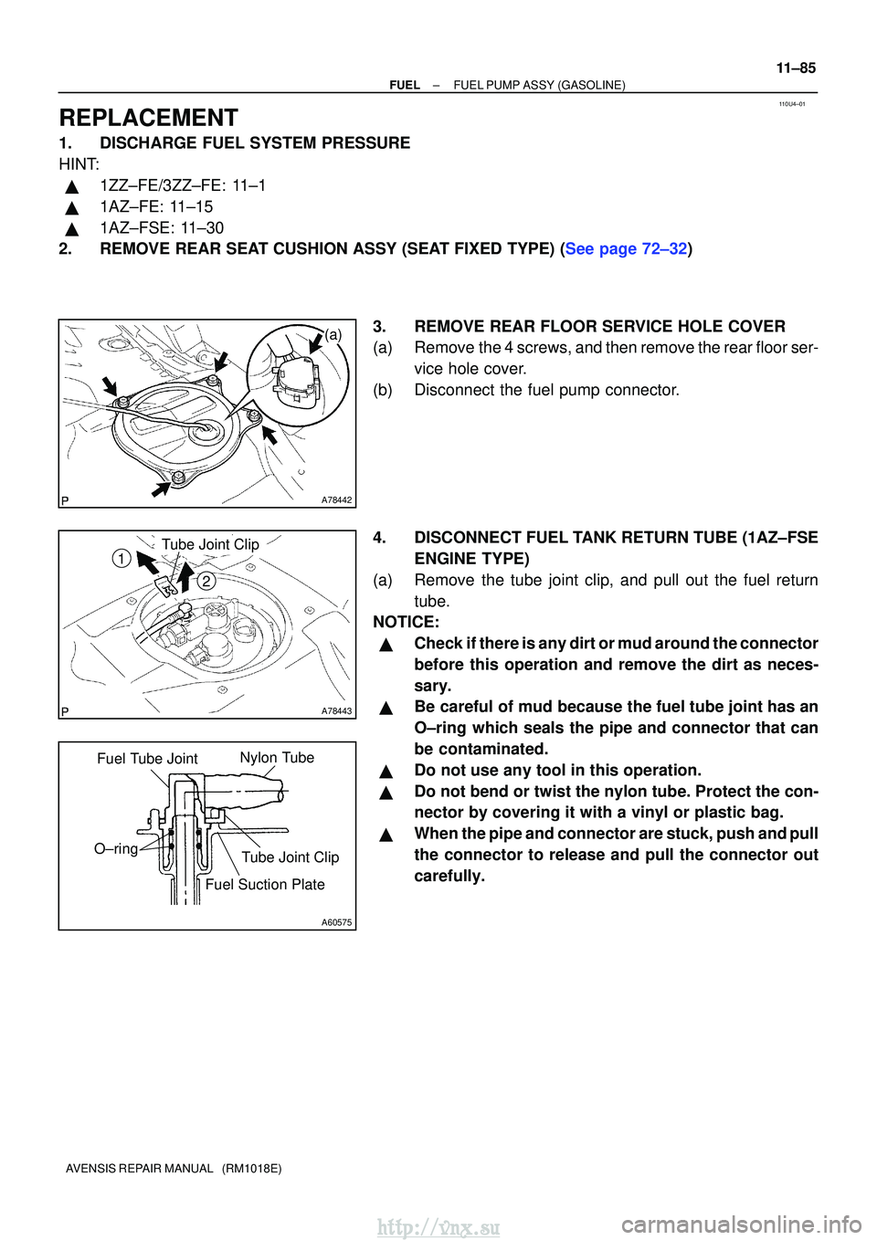
3. REMOVE REAR FLOOR SERVICE HOLE COVER
(a) Remove the 4 screws, and then remove the rear floor ser-vice hole cover.
(b) Disconnect the fuel pump connector.
4. DISCONNECT FUEL TANK RETURN TUBE (1AZ±FSE ENGINE TYPE)
(a) Remove the tube joint clip, and pull out the fuel return tube.
NOTICE:
�Check if there is any dirt or mud around the connector
before this operation and remove the dirt as neces-
sary.
�Be careful of mud because the fuel tube joint has an
O±ring which seals the pipe and connector that can
be contaminated.
�Do not use any tool in this operation.
�Do not bend or twist the nylon tube. Protect the con-
nector by covering it with a vinyl or plastic bag.
�When the pipe and connector are stuck, push and pull
the connector to release and pull the connector out
carefully.
http://vnx.su
Page 341 of 2234
A81614
Push
A81615
Push
A81616
Tube Joint Clip
Collar
2
1
11±88
±
FUELFUEL PUMP ASSY(GASOLINE)
AVENSIS REPAIR MANUAL (RM1018E)
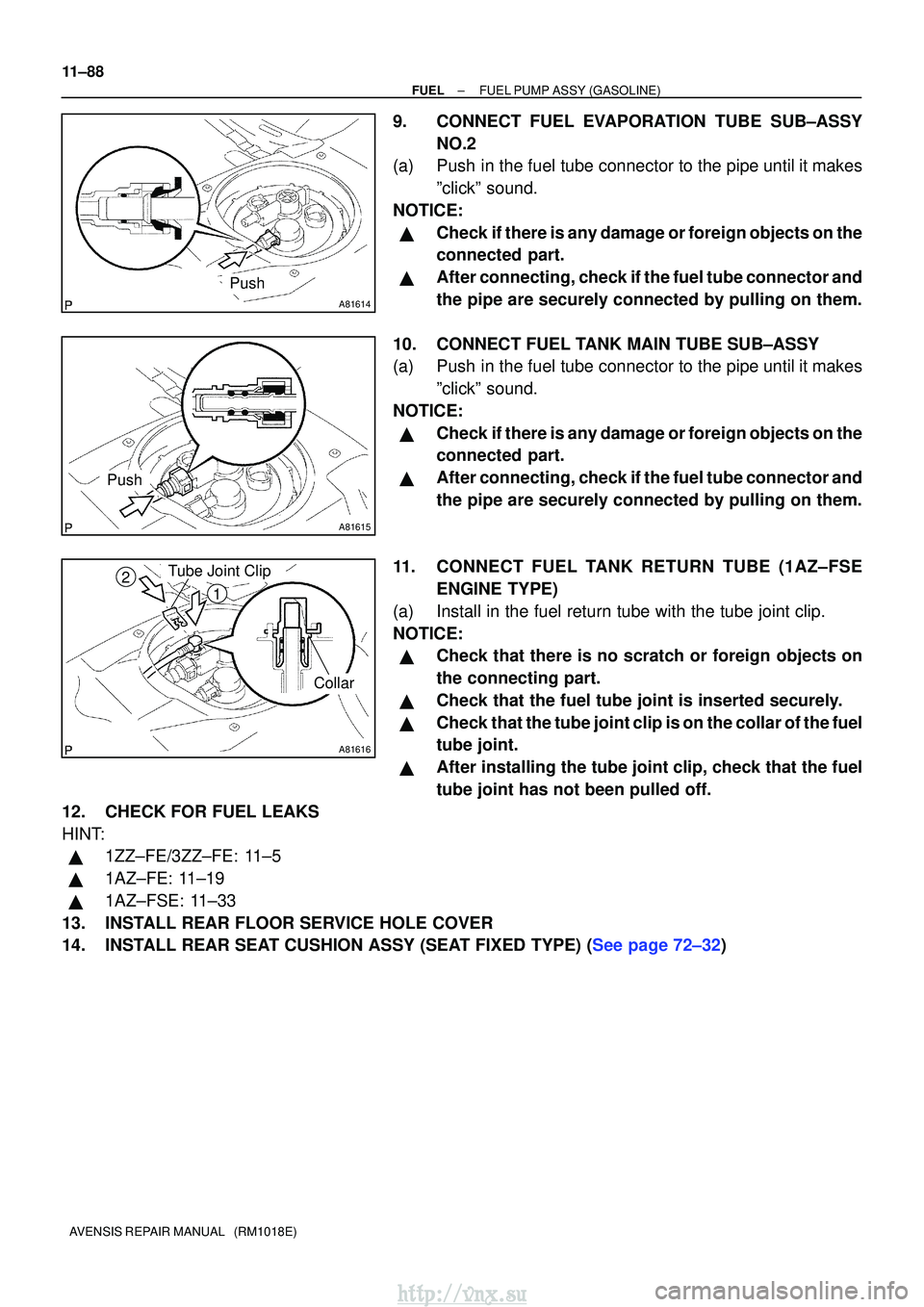
9.CONNECT FUEL EVAPORATION TUBE SUB±ASSY NO.2
(a)Push in the fuel tube connector to the pipe until it makes
ºclickº sound.
NOTICE:
�Check if there is any damage or foreign objects on the
connected part.
�After connecting, check if the fuel tube connector and
the pipe are securely connected by pulling on them.
10.CONNECT FUEL TANK MAIN TUBE SUB±ASSY
(a)Push in the fuel tube connector to the pipe until it makes ºclickº sound.
NOTICE:
�Check if there is any damage or foreign objects on the
connected part.
�After connecting, check if the fuel tube connector and
the pipe are securely connected by pulling on them.
11.C ONNECT FUEL TANK RETURN TUBE (1AZ±F SE
ENGINE TYPE)
(a)Install in the fuel return tube with the tube joint clip.
NOTICE:
�Check that there is no scratch or foreign objects on
the connecting part.
�Check that the fuel tube joint is inserted securely.
�Check that the tube joint clip is on the collar of the fuel
tube joint.
�After installing the tube joint clip, check that the fuel
tube joint has not been pulled off.
12.CHECK FOR FUEL LEAKS
HINT:
�1ZZ±FE/3ZZ±FE: 11±5
�1AZ±FE: 11±19
�1AZ±FSE: 11±33
13.INSTALL REAR FLOOR SERVICE HOLE COVER
14.INSTALL REAR SEAT CUSHION ASSY (SEAT FIXED TYPE) (See page 72±32)
http://vnx.su
Page 344 of 2234
110UX±01
Fuel Tube Connector
A50710
A60083
Fuel Pipe
Clamp No.1
AA
B12941
±
FUELFUEL SYSTEM(1AZ±FE)
11±19
AVENSIS REPAIR MANUAL (RM1018E)
ON±VEHICLE INSPECTION
1.CHECK FUEL PRESSURE
(a)Discharge the pressure in the fuel system and take pre-
cautions for possible fuel spillage.(See page 11±15)
(b) Check that the battery voltage is above 12 V.
(c) Disconnect the negative (±) battery cable.
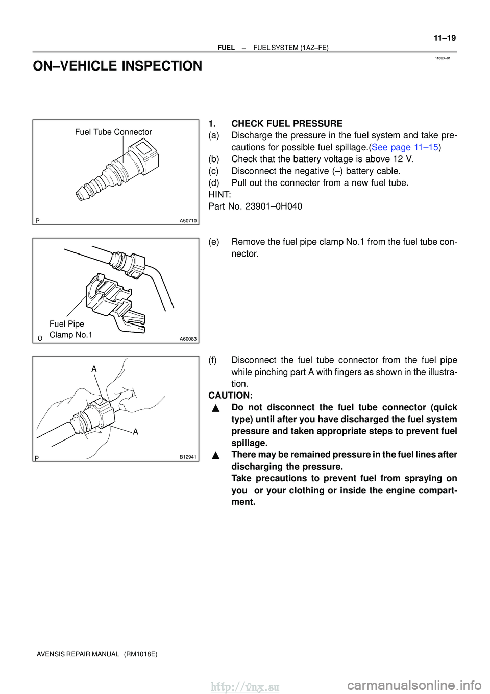
(d) Pull out the connecter from a new fuel tube.
HINT:
Part No. 23901±0H040
(e) Remove the fuel pipe clamp No.1 from the fuel tube con- nector.
(f) Disconnect the fuel tube connector from the fuel pipe while pinching part A with fingers as shown in the illustra-
tion.
CAUTION:
�Do not disconnect the fuel tube connector (quick
type) until after you have discharged the fuel system
pressure and taken appropriate steps to prevent fuel
spillage.
�There may be remained pressure in the fuel lines after
discharging the pressure.
Take precautions to prevent fuel from spraying on
you or your clothing or inside the engine compart-
ment.
http://vnx.su
Page 345 of 2234
No.1 Fuel Pipe
Fuel Tube Connector
SST
(Clip)
SST (T joint)SST
SST
(Hose)
B12975
11±20
±
FUEL FUEL SYSTEM (1AZ±FE)
AVENSIS REPAIR MANUAL (RM1018E)
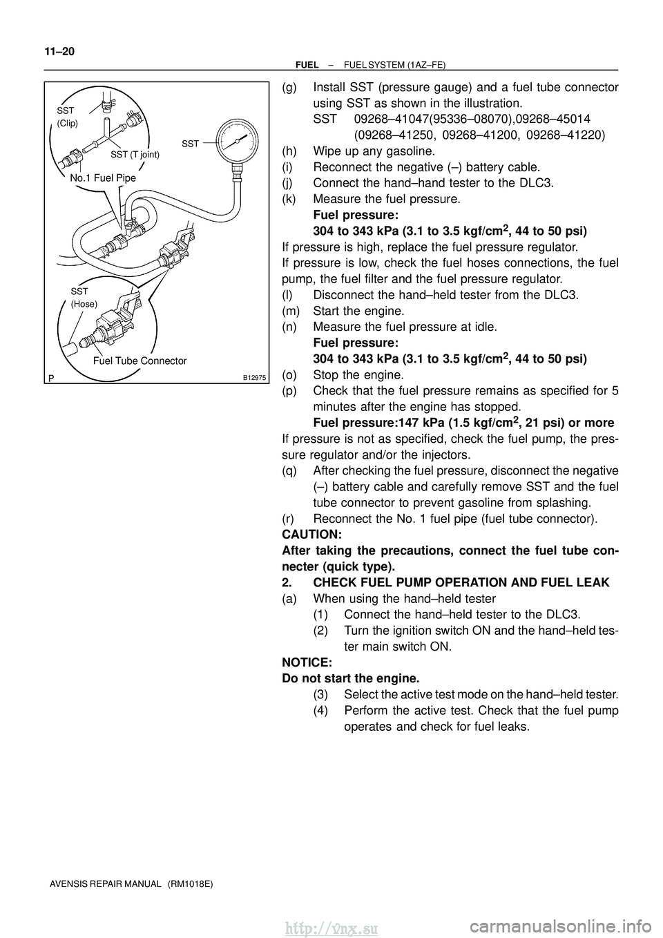
(g) Install SST (pressure gauge) and a fuel tube connector using SST as shown in the illustration.
SST 09268±41047(95336±08070),09268±45014 (09268±41250, 09268±41200, 09268±41220)
(h) Wipe up any gasoline.
(i) Reconnect the negative (±) battery cable.
(j) Connect the hand±hand tester to the DLC3.
(k) Measure the fuel pressure. Fuel pressure:
304 to 343 kPa (3.1 to 3.5 kgf/cm
2, 44 to 50 psi)
If pressure is high, replace the fuel pressure regulator.
If pressure is low, check the fuel hoses connections, the fuel
pump, the fuel filter and the fuel pressure regulator.
(l) Disconnect the hand±held tester from the DLC3.
(m) Start the engine.
(n) Measure the fuel pressure at idle. Fuel pressure:
304 to 343 kPa (3.1 to 3.5 kgf/cm
2, 44 to 50 psi)
(o) Stop the engine.
(p) Check that the fuel pressure remains as specified for 5 minutes after the engine has stopped.
Fuel pressure:147 kPa (1.5 kgf/cm
2, 21 psi) or more
If pressure is not as specified, check the fuel pump, the pres-
sure regulator and/or the injectors.
(q) After checking the fuel pressure, disconnect the negative (±) battery cable and carefully remove SST and the fuel
tube connector to prevent gasoline from splashing.
(r) Reconnect the No. 1 fuel pipe (fuel tube connector).
CAUTION:
After taking the precautions, connect the fuel tube con-
necter (quick type).
2. CHECK FUEL PUMP OPERATION AND FUEL LEAK
(a) When using the hand±held tester (1) Connect the hand±held tester to the DLC3.
(2) Turn the ignition switch ON and the hand±held tes-
ter main switch ON.
NOTICE:
Do not start the engine. (3) Select the active test mode on the hand±held tester.
(4) Perform the active test. Check that the fuel pumpoperates and check for fuel leaks.
http://vnx.su
Page 350 of 2234
B16534Push
B16535Pull
11±18
±
FUELFUEL SYSTEM(1AZ±FE)
AVENSIS REPAIR MANUAL (RM1018E)
(f)Observe these precautions when connecting the fuel tube connectors (Quick Type):
(1)Check that there is no damage or foreign objects inthe connected part of the pipe.
(2)Match the axis of the connector with the axis of the pipe, and push into the connector until the connec-
tor makes a ºclickº sound. If the connection is tight,
apply little amount of fresh engine oil on the tip of the
pipe.
(3)After having finished the connection, check if the pipe and the connector are securely connected by
pulling on them.
(4)Check for fuel leaks.
4.CHECK FOR FUEL LEAKS
(a)Check that there are no fuel leaks after doing maintenance anywhere on t\
he fuel system. (See page 11±19)
http://vnx.su
Page 354 of 2234
SST
A50700
B00069
A16628A32859
±
FUEL FUEL SYSTEM (1ZZ±FE/3ZZ±FE)
11±9
AVENSIS REPAIR MANUAL (RM1018E)
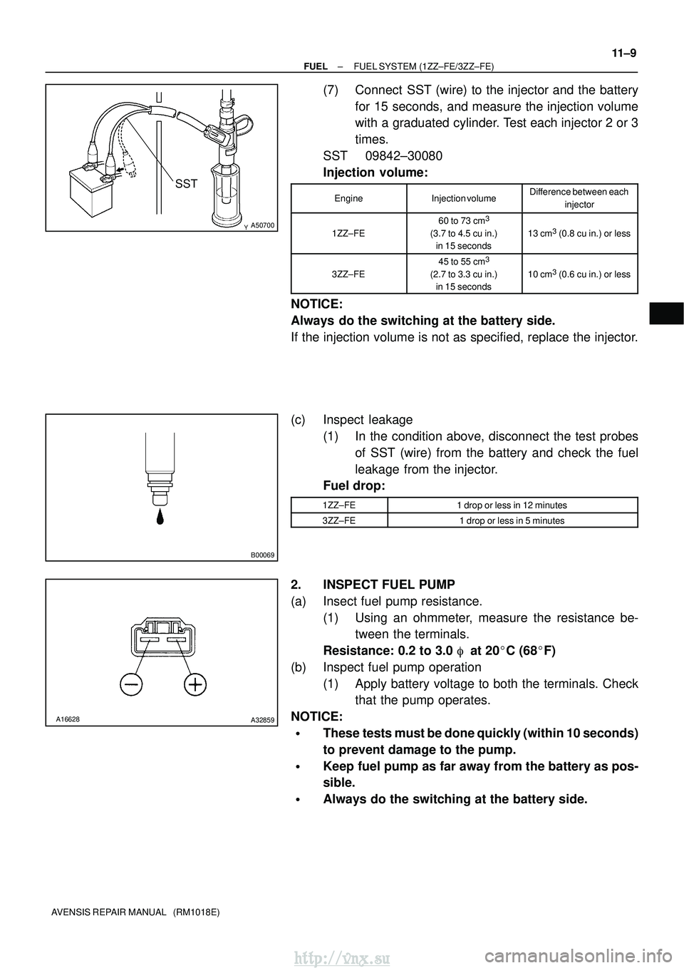
(7) Connect SST (wire) to the injector and the battery
for 15 seconds, and measure the injection volume
with a graduated cylinder. Test each injector 2 or 3
times.
SST 09842±30080
Injection volume:
EngineInjection volumeDifference between each
injector
1ZZ±FE
60 to 73 cm3
(3.7 to 4.5 cu in.)in 15 seconds13 cm3 (0.8 cu in.) or less
3ZZ±FE
45 to 55 cm3
(2.7 to 3.3 cu in.)in 15 seconds10 cm3 (0.6 cu in.) or less
NOTICE:
Always do the switching at the battery side.
If the injection volume is not as specified, replace the injector.
(c) Inspect leakage (1) In the condition above, disconnect the test probesof SST (wire) from the battery and check the fuel
leakage from the injector.
Fuel drop:
1ZZ±FE1 drop or less in 12 minutes
3ZZ±FE1 drop or less in 5 minutes
2. INSPECT FUEL PUMP
(a) Insect fuel pump resistance.
(1) Using an ohmmeter, measure the resistance be-tween the terminals.
Resistance: 0.2 to 3.0 � at 20 �C (68� F)
(b) Inspect fuel pump operation (1) Apply battery voltage to both the terminals. Checkthat the pump operates.
NOTICE:
�These tests must be done quickly (within 10 seconds)
to prevent damage to the pump.
�Keep fuel pump as far away from the battery as pos-
sible.
�Always do the switching at the battery side.
http://vnx.su