Page 14 of 2234

NEW MODEL OUTLINE
����\b��
����\b��
����\b��
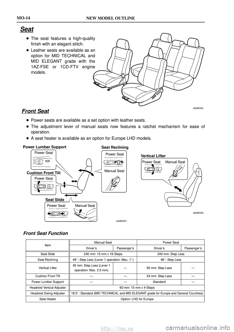
Power Lumber Support
Power Seat
Cushion Front Tilt
Power Seat
Seat Slide
Power Seat Manual Seat
Seat Reclining
Power SeatVertical Lifter
Power Seat Manual Seat
Manual Seat
MO-14
Seat
� The seat features a high-quality
finish with an elegant stitch.
� Leather seats are available as an
option for MID TECHNICAL and
MID ELEGANT grade with the
1AZ-FSE or 1CD-FTV engine
models.
Front Seat
�Power seats are available as a set option with leather seats.
� The adjustment lever of manual seats now features a ratchet mechanism fo\
r ease of
operation.
� A seat heater is available as an option for Europe LHD models.
Front Seat Function
ItemManual Seat Power SeatItemDriver'sPassenger's Driver'sPassenger's
Seat Slide 240 mm: 15 mm x 16-Steps 240 mm: Step Less
Seat Reclining 48 �: Step Less (Lever 1 operation: Max. 1 �)4 8�: Step Less
Vertical Lifter 45 mm: Step Less (Lever 1
operation: Max. 2.5 mm) Ð
50 mm: Step Less Ð
Cushion Front Tilt ÐÐ34 mm: Step Less Ð
Power Lumber Support ÐÐStandard Ð
Headrest Vertical Adjuster 60 mm: 15 mm x 4-Steps
Headrest Swing Adjuster 18.5 �: Standard (MID TECHNICAL and MID ELEGANT grade for Europe and General Countries)
Seat Heater Option: LHD for Europe
http://vnx.su
Page 1009 of 2234

2600L±02
F44617
Front:AB
F44618
Rear:
C D
SA3213
A
D B
Front
C
F44619
26±6
±
FRONT SUSPENSION FRONT WHEEL ALIGNMENT
AVENSIS REPAIR MANUAL (RM1018E)
FRONT WHEEL ALIGNMENT
ADJUSTMENT
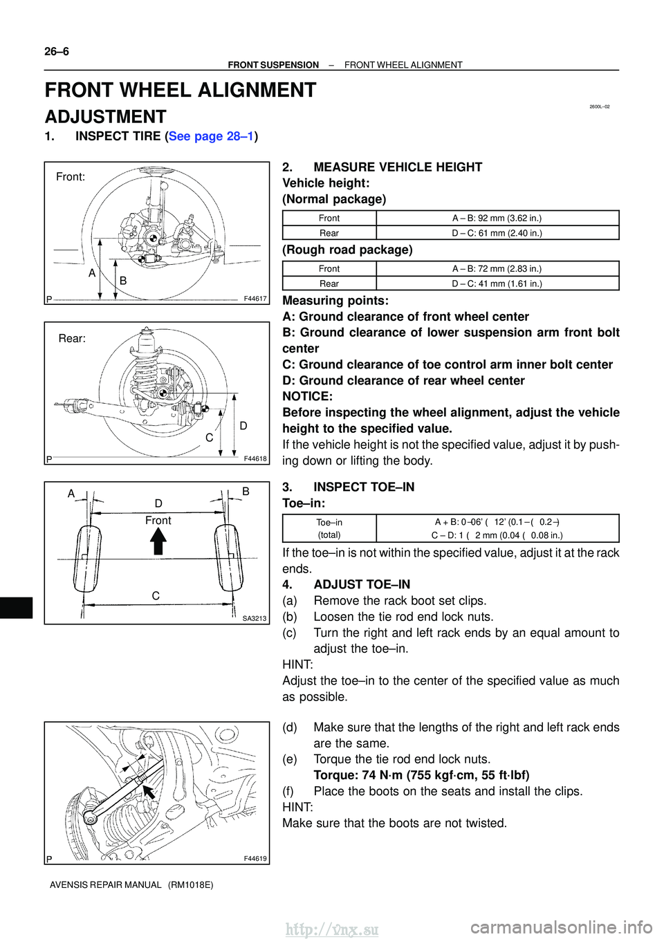
1.INSPECT TIRE (See page 28±1) 2. MEASURE VEHICLE HEIGHT
Vehicle height:
(Normal package)
FrontA ± B: 92 mm (3.62 in.)
RearD ± C: 61 mm (2.40 in.)
(Rough road package)
FrontA ± B: 72 mm (2.83 in.)
RearD ± C: 41 mm (1.61 in.)
Measuring points:
A: Ground clearance of front wheel center
B: Ground clearance of lower suspension arm front bolt
center
C: Ground clearance of toe control arm inner bolt center
D: Ground clearance of rear wheel center
NOTICE:
Before inspecting the wheel alignment, adjust the vehicle
height to the specified value.
If the vehicle height is not the specified value, adjust it by push-
ing down or lifting the body.
3. INSPECT TOE±IN
Toe±in:
Toe±in(total)A + B: 0� 06' � 12' (0.1 � � 0.2� )
C ± D: 1 � 2 mm (0.04 � 0.08 in.)
If the toe±in is not within the specified value, adjust it at the rack
ends.
4. ADJUST TOE±IN
(a) Remove the rack boot set clips.
(b) Loosen the tie rod end lock nuts.
(c) Turn the right and left rack ends by an equal amount to
adjust the toe±in.
HINT:
Adjust the toe±in to the center of the specified value as much
as possible.
(d) Make sure that the lengths of the right and left rack ends are the same.
(e) Torque the tie rod end lock nuts.
Torque: 74 N´m (755 kgf´cm, 55 ft´lbf)
(f) Place the boots on the seats and install the clips.
HINT:
Make sure that the boots are not twisted.
http://vnx.su
Page 1495 of 2234

650SV±01
I33423
V LH LineV RH LineV Line
Ground
H Line
±
LIGHTING HEADLAMP UNIT LH
65±19
AVENSIS REPAIR MANUAL (RM1018E)
ADJUSTMENT
1. HEADLIGHT AIM ONLY
HINT:
�Perform aiming adjustment with Low±beam.
�Since the Low±beam light and the High±beam light is a
unit, if aiming on either side is connect, the other side
should also be connect.
However, check both beams just to make sure.
(a) Prepare vehicle in the following conditions.
�Check that any damage or deformation does not exist on
the body around the headlights.
�Fuel tank is full.
�The tire inflation pressure is at the specified level.
�Vehicle is parked at a level surface.
�A person having an average weight sits in the driver's
seat.
�Vehicle is bounced up and down to stabilize the suspen-
sion to the normal position.
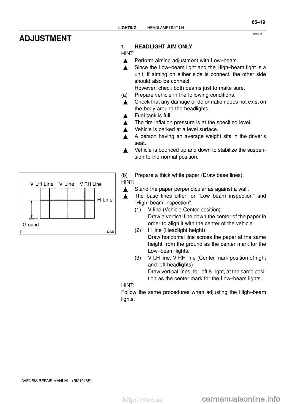
(b) Prepare a thick white paper (Draw base lines).
HINT:
�Stand the paper perpendicular as against a wall.
�The base lines differ for ºLow±beam inspectionº and
ºHigh±beam inspectionº.
(1) V line (Vehicle Center position) Draw a vertical line down the center of the paper in
order to align it with the center of the vehicle.
(2) H line (Headlight height)
Draw horizontal line across the paper at the same
height from the ground as the center mark for the
Low±beam lights.
(3) V LH line, V RH line (Center mark position of right and left headlights)
Draw vertical lines, for left & right, at the same posi-
tion as the center mark for the Low±beam lights.
HINT:
Follow the same procedures when adjusting the High±beam
lights.
http://vnx.su