Page 368 of 2234
B16534Push
B16535Pull
11±32
±
FUELFUEL SYSTEM(1AZ±FSE)
AVENSIS REPAIR MANUAL (RM1018E)
(d)Observe these precautions when connecting the fuel tube connectors (Quick Type):
(1)Check that there is no damage or foreign objects inthe connected part of the pipe.
(2)Match the axis of the connector with the axis of the pipe, and push into the connector until the connec-
tor makes a ºclickº sound. If the connection is tight,
apply little amount of fresh engine oil on the tip of the
pipe.
(3)After having finished the connection, check if the pipe and the connector are securely connected by
pulling on them.
(4)Check for fuel leaks.
4.CHECK FOR FUEL LEAKS
(a)Check that there are no fuel leaks after doing maintenance anywhere on t\
he fuel system. (See page 11±33)
http://vnx.su
Page 388 of 2234
A77894
A77891
A77892
A77893
UpperFuel Tank
Rear
Hose Clamp
A81617
Push
11±98
±
FUEL FUEL TANK ASSY (GASOLINE)
AVENSIS REPAIR MANUAL (RM1018E)
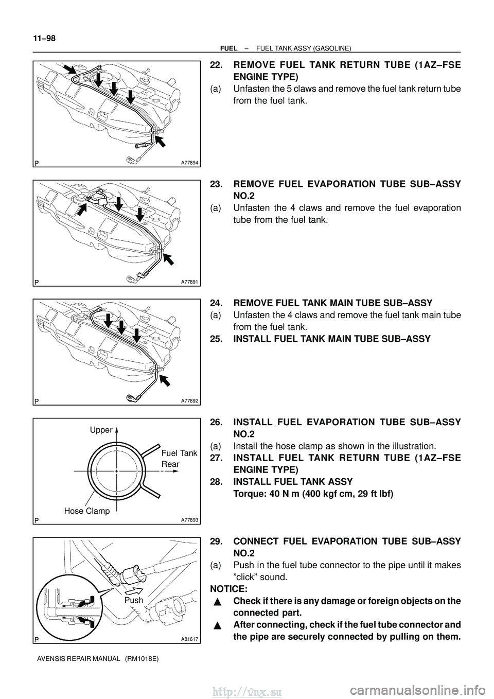
22. REMOVE FUEL TANK RETURN TUBE (1AZ±FSE ENGINE TYPE)
(a) Unfasten the 5 claws and remove the fuel tank return tube
from the fuel tank.
23. REMOVE FUEL EVAPORATION TUBE SUB±ASSY NO.2
(a) Unfasten the 4 claws and remove the fuel evaporation tube from the fuel tank.
24. REMOVE FUEL TANK MAIN TUBE SUB±ASSY
(a) Unfasten the 4 claws and remove the fuel tank main tube from the fuel tank.
25. INSTALL FUEL TANK MAIN TUBE SUB±ASSY
26. INSTALL FUEL EVAPORATION TUBE SUB±ASSY NO.2
(a) Install the hose clamp as shown in the illustration.
27. INSTALL FUEL TANK RETURN TUBE (1AZ±FSE ENGINE TYPE)
28. INSTALL FUEL TANK ASSY Torque: 40 N �m (400 kgf� cm, 29 ft�lbf)
29. CONNECT FUEL EVAPORATION TUBE SUB±ASSY NO.2
(a) Push in the fuel tube connector to the pipe until it makes
ºclickº sound.
NOTICE:
�Check if there is any damage or foreign objects on the
connected part.
�After connecting, check if the fuel tube connector and
the pipe are securely connected by pulling on them.
http://vnx.su
Page 389 of 2234
A81618
Push
2
1Retainer
A77857
A78440
New Gasket
A77857
±
FUEL FUEL TANK ASSY (GASOLINE)
11±99
AVENSIS REPAIR MANUAL (RM1018E)
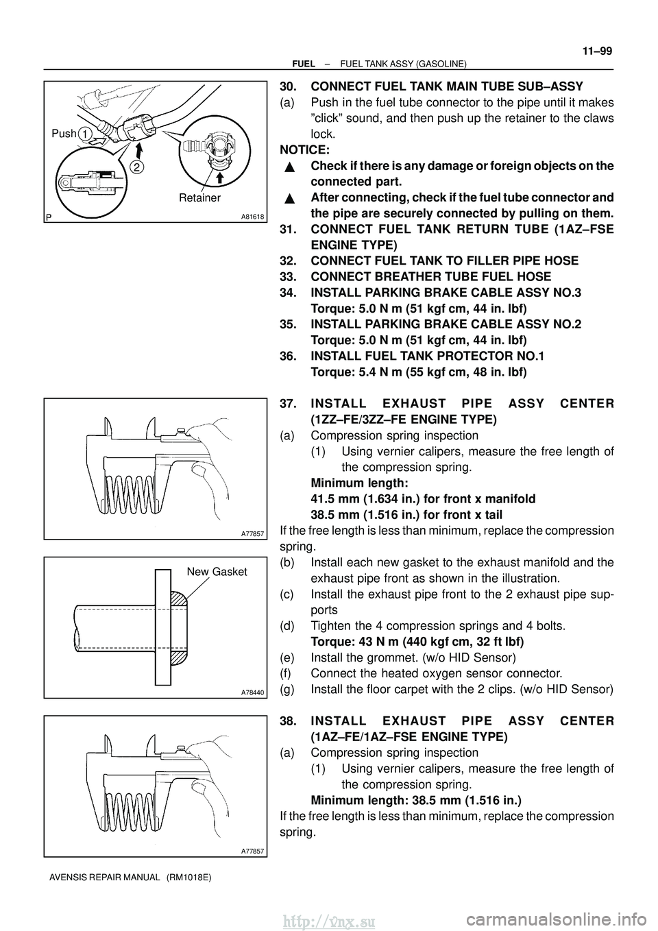
30. CONNECT FUEL TANK MAIN TUBE SUB±ASSY
(a) Push in the fuel tube connector to the pipe until it makes
ºclickº sound, and then push up the retainer to the claws
lock.
NOTICE:
�Check if there is any damage or foreign objects on the
connected part.
�After connecting, check if the fuel tube connector and
the pipe are securely connected by pulling on them.
31. CONNECT FUEL TANK RETURN TUBE (1AZ±FSE ENGINE TYPE)
32. CONNECT FUEL TANK TO FILLER PIPE HOSE
33. CONNECT BREATHER TUBE FUEL HOSE
34. INSTALL PARKING BRAKE CABLE ASSY NO.3
Torque: 5.0 N �m (51 kgf �cm, 44 in. �lbf)
35. INSTALL PARKING BRAKE CABLE ASSY NO.2
Torque: 5.0 N �m (51 kgf �cm, 44 in. �lbf)
36. INSTALL FUEL TANK PROTECTOR NO.1 Torque: 5.4 N �m (55 kgf �cm, 48 in. �lbf)
37. INSTALL EXHAUST PIPE ASSY CENTER (1ZZ±FE/3ZZ±FE ENGINE TYPE)
(a) Compression spring inspection (1) Using vernier calipers, measure the free length ofthe compression spring.
Minimum length:
41.5 mm (1.634 in.) for front x manifold
38.5 mm (1.516 in.) for front x tail
If the free length is less than minimum, replace the compression
spring.
(b) Install each new gasket to the exhaust manifold and the
exhaust pipe front as shown in the illustration.
(c) Install the exhaust pipe front to the 2 exhaust pipe sup- ports
(d) Tighten the 4 compression springs and 4 bolts. Torque: 43 N �m (440 kgf� cm, 32 ft�lbf)
(e) Install the grommet. (w/o HID Sensor)
(f) Connect the heated oxygen sensor connector.
(g) Install the floor carpet with the 2 clips. (w/o HID Sensor)
38. INSTALL EXHAUST PIPE ASSY CENTER (1AZ±FE/1AZ±FSE ENGINE TYPE)
(a) Compression spring inspection
(1) Using vernier calipers, measure the free length ofthe compression spring.
Minimum length: 38.5 mm (1.516 in.)
If the free length is less than minimum, replace the compression
spring.
http://vnx.su
Page 390 of 2234
A78440
New Gasket
11±100
±
FUELFUEL TANK ASSY(GASOLINE)
AVENSIS REPAIR MANUAL (RM1018E)
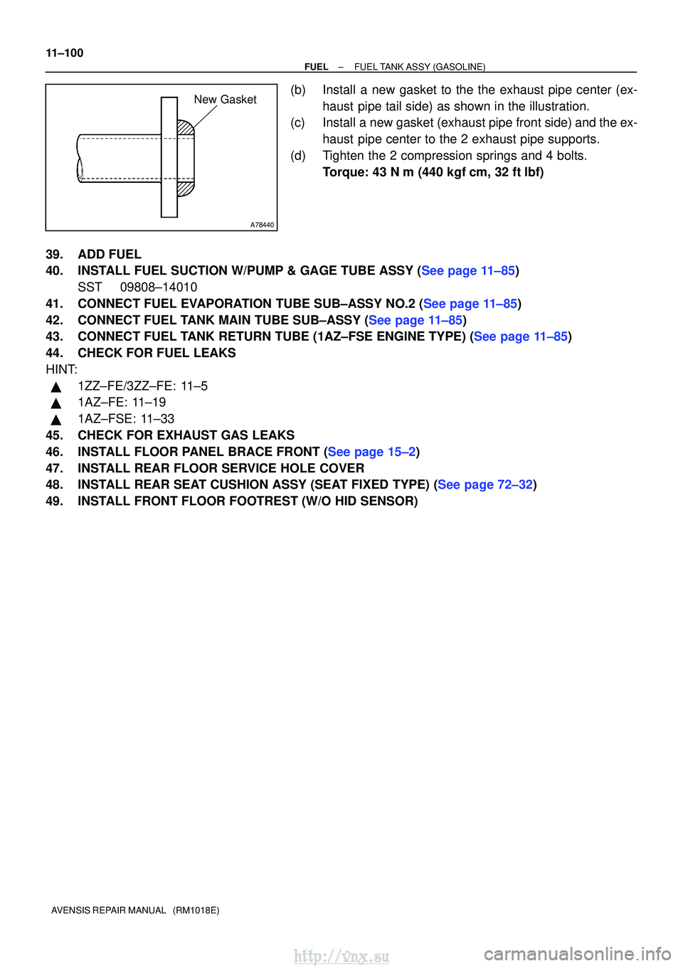
(b)Install a new gasket to the the exhaust pipe center (ex- haust pipe tail side) as shown in the illustration.
(c)Install a new gasket (exhaust pipe front side) and the ex-
haust pipe center to the 2 exhaust pipe supports.
(d)Tighten the 2 compression springs and 4 bolts. Torque: 43 N �m (440 kgf�cm, 32 ft�lbf)
39.ADD FUEL
40.INSTALL FUEL SUCTION W/PUMP & GAGE TUBE ASSY (See page 11±85) SST 09808±14010
41.CONNECT FUEL EVAPORATION TUBE SUB±ASSY NO.2 (See page 11±85)
42.CONNECT FUEL TANK MAIN TUBE SUB±ASSY (See page 11±85)
43.CONNECT FUEL TANK RETURN TUBE (1AZ±FSE ENGINE TYPE) (See page 11±85)
44. CHECK FOR FUEL LEAKS
HINT:
�1ZZ±FE/3ZZ±FE: 11±5
�1AZ±FE: 11±19
�1AZ±FSE: 11±33
45. CHECK FOR EXHAUST GAS LEAKS
46.INSTALL FLOOR PANEL BRACE FRONT (See page 15±2)
47. INSTALL REAR FLOOR SERVICE HOLE COVER
48.INSTALL REAR SEAT CUSHION ASSY (SEAT FIXED TYPE) (See page 72±32)
49. INSTALL FRONT FLOOR FOOTREST (W/O HID SENSOR)
http://vnx.su
Page 399 of 2234
A79149
SST
30 cm
(11.81 in.)
11±74
±
FUELINJECTION OR SUPPLY PUMP ASSY(1CD±FTV)
AVENSIS REPAIR MANUAL (RM1018E)
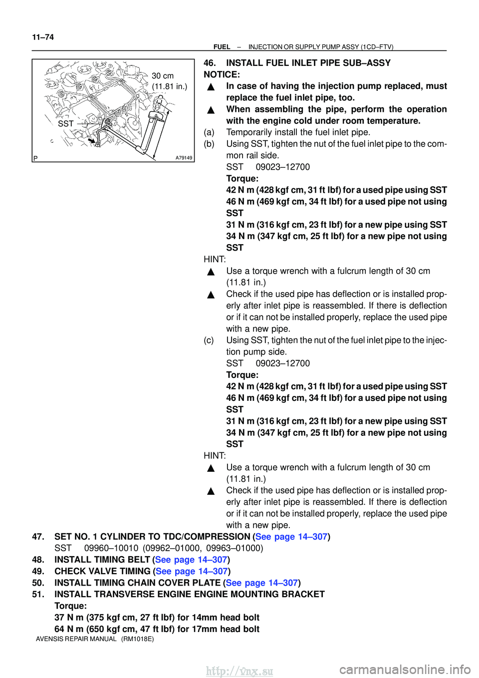
46.INSTALL FUEL INLET PIPE SUB±ASSY
NOTICE:
�In case of having the injection pump replaced, must
replace the fuel inlet pipe, too.
�When assembling the pipe, perform the operation
with the engine cold under room temperature.
(a)Temporarily install the fuel inlet pipe.
(b)Using SST, tighten the nut of the fuel inlet pipe to the com-
mon rail side.
SST09023±12700
Torque:
42 N�m (428 kgf�cm, 31 ft�lbf) for a used pipe using SST
46 N�m (469 kgf�cm, 34 ft�lbf) for a used pipe not using
SST
31 N �m (316 kgf�cm, 23 ft�lbf) for a new pipe using SST
34 N�m (347 kgf �cm, 25 ft�lbf) for a new pipe not using
SST
HINT:
�Use a torque wrench with a fulcrum length of 30 cm
(11.81 in.)
�Check if the used pipe has deflection or is installed prop-
erly after inlet pipe is reassembled. If there is deflection
or if it can not be installed properly, replace the used pipe
with a new pipe.
(c)Using SST, tighten the nut of the fuel inlet pipe to the injec-
tion pump side.
SST09023±12700
Torque:
42 N�m (428 kgf�cm, 31 ft�lbf) for a used pipe using SST
46 N�m (469 kgf�cm, 34 ft�lbf) for a used pipe not using
SST
31 N �m (316 kgf�cm, 23 ft�lbf) for a new pipe using SST
34 N�m (347 kgf �cm, 25 ft�lbf) for a new pipe not using
SST
HINT:
�Use a torque wrench with a fulcrum length of 30 cm
(11.81 in.)
�Check if the used pipe has deflection or is installed prop-
erly after inlet pipe is reassembled. If there is deflection
or if it can not be installed properly, replace the used pipe
with a new pipe.
47.SET NO. 1 CYLINDER TO TDC/COMPRESSION(See page 14±307) SST 09960±10010 (09962±01000, 09963±01000)
48.INSTALL TIMING BELT(See page 14±307)
49.CHECK VALVE TIMING(See page 14±307)
50.INSTALL TIMING CHAIN COVER PLATE(See page 14±307)
51. INSTALL TRANSVERSE ENGINE ENGINE MOUNTING BRACKET Torque:
37 N�m (375 kgf� cm, 27 ft�lbf) for 14mm head bolt
64 N� m (650 kgf� cm, 47 ft�lbf) for 17mm head bolt
http://vnx.su
Page 400 of 2234
±
FUEL INJECTION OR SUPPLY PUMP ASSY (1CD±FTV)
11±75
AVENSIS REPAIR MANUAL (RM1018E)
52.INSTALL TIMING BELT GUIDE(See page 14±307)
53.INSTALL TIMING BELT NO.1 COVER(See page 14±307)
54.INSTALL TIMING BELT NO.2 COVER(See page 14±307)
55. INSTALL IDLER PULLEY SUB±ASSY
Torque: 40 N �m (408 kgf� cm, 30 ft�lbf)
56.INSTALL CRANKSHAFT PULLEY(See page 14±307) SST 09213±54015 (90105±08076), 09330±00021
57.INSTALL ENGINE MOUNTING INSULATOR SUB±ASSY RH(See page 14±307)
58. INSTALL INJECTOR DRIVER Torque: 5.0 N �m (51 kgf �cm, 44 in. �lbf)
59. ADJUST V (COOLER COMPRESSOR TO CRANKSHAFT PULLEY) BELT NO.1 (See page 14±269)
60.INSTALL RADIATOR RESERVE TANK ASSY(See page 16±50)
61. INSTALL ENGINE COVER NO.1 Torque: 8.0 N �m (82 kgf �cm, 71 in. �lbf)
62.INSTALL AIR CLEANER ASSY (See page 11±60)
63. INSTALL FRONT WHEEL RH
Torque: 103 N� m (1,050 kgf�cm, 76 ft �lbf)
64.ADD ENGINE COOLANT(See page 16±44)
65.CHECK FOR ENGINE COOLANT LEAKS(See page 16±37)
66.CHECK FOR FUEL LEAKS(See page 11±60)
http://vnx.su
Page 405 of 2234
A79187
O±ringBack±up ring
B08249
A80111
180
�
90�
11±62
±
FUEL INJECTOR ASSY (1CD±FTV)
AVENSIS REPAIR MANUAL (RM1018E)
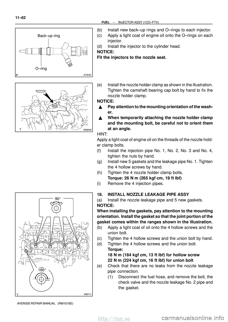
(b) Install new back±up rings and O±rings to each injector.
(c) Apply a light coat of engine oil onto the O±rings on each injector.
(d) Install the injector to the cylinder head.
NOTICE:
Fit the injectors to the nozzle seat.
(e) Install the nozzle holder clamp as shown in the illustration. Tighten the camshaft bearing cap bolt by hand to fix the
nozzle holder clamp.
NOTICE:
�Pay attention to the mounting orientation of the wash-
er.
�When temporarily attaching the nozzle holder clamp
and the mounting bolt, be careful not to orient them
at an angle.
HINT:
Apply a light coat of engine oil on the threads of the nozzle hold-
er clamp bolts.
(f) Install the injection pipe No. 1, No. 2, No. 3 and No. 4,
tighten the nuts by hand.
(g) Install new 5 gaskets and the leakage pipe No. 1. Tighten
the 4 hollow screws by hand.
(h) Tighten the 4 nozzle holder clamp bolts. Torque: 26 N �m (265 kgf� cm, 19 ft�lbf)
(i) Remove the 4 injection pipes.
18. INSTALL NOZZLE LEAKAGE PIPE ASSY
(a) Install the nozzle leakage pipe and 5 new gaskets.
NOTICE:
When installing the gaskets, pay attention to the mounting
orientation. Install the gasket so that the joint portion of the
gasket comes within the ranges shown in the illustration.
(b) Apply a light coat of oil onto the 4 hollow screws and the union bolt.
(c) Tighten the 4 hollow screws and the union bolt by hand.
(d) Tighten the 4 hollow screws and the union bolt. Torque:
18 N�m (184 kgf� cm, 13 ft�lbf) for hollow screw
22 N� m (224 kgf� cm, 16 ft�lbf) for union bolt
(e) Check that there are no leaks from the nozzle leakage pipe connection.
(1) Disconnect the fuel hose, and remove the bolt, thecheck valve and the nozzle leakage No. 2 pipe and
the gasket.
http://vnx.su
Page 406 of 2234
A80119
New Gasket
Hollow
Screw
Union
BoltSST
Nozzle Leakage
No. 2 Pipe
New Gasket
SST
A79146
Check
Valve
Nozzle Leakage
No. 2 Pipe
New Gasket
A09663
:Seal Packing
±
FUEL INJECTOR ASSY (1CD±FTV)
11±63
AVENSIS REPAIR MANUAL (RM1018E)
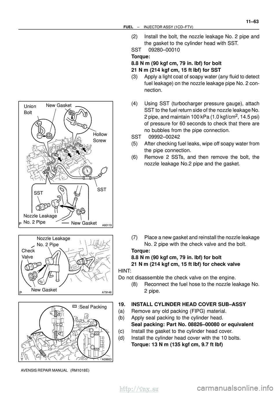
(2) Install the bolt, the nozzle leakage No. 2 pipe and
the gasket to the cylinder head with SST.
SST 09280±00010
Torque:
8.8 N �m (90 kgf �cm, 79 in. �lbf) for bolt
21 N� m (214 kgf� cm, 15 ft�lbf) for SST
(3) Apply a light coat of soapy water (any fluid to detect
fuel leakage) on the nozzle leakage pipe No. 2 con-
nection.
(4) Using SST (turbocharger pressure gauge), attach SST to the fuel return side of the nozzle leakage No.
2 pipe, and maintain 100 kPa (1.0 kgf/cm
2, 14.5 psi)
of pressure for 60 seconds to check that there are
no bubbles from the pipe connection.
SST 09992±00242
(5) After checking fuel leaks, wipe off soapy water from
the pipe connection.
(6) Remove 2 SSTs, and then remove the bolt, the nozzle leakage No.2 pipe and the gasket.
(7) Place a new gasket and reinstall the nozzle leakage No. 2 pipe with the check valve and the bolt.
Torque:
8.8 N� m (90 kgf �cm, 79 in. �lbf) for bolt
21 N� m (214 kgf� cm, 15 ft�lbf) for check valve
HINT:
Do not disassemble the check valve on the engine. (8) Reconnect the fuel hose to the nozzle leakage No.
2 pipe.
19. INSTALL CYLINDER HEAD COVER SUB±ASSY
(a) Remove any old packing (FIPG) material.
(b) Apply seal packing to the cylinder head. Seal packing: Part No. 08826±00080 or equivalent
(c) Install the gasket to the cylinder head cover.
(d) Install the cylinder head cover with the 10 bolts. Torque: 13 N �m (135 kgf� cm, 9.7 ft�lbf)
http://vnx.su